EP2852420B1 - Kollapsresistenter quellbarer katheter - Google Patents
Kollapsresistenter quellbarer katheter Download PDFInfo
- Publication number
- EP2852420B1 EP2852420B1 EP13794584.6A EP13794584A EP2852420B1 EP 2852420 B1 EP2852420 B1 EP 2852420B1 EP 13794584 A EP13794584 A EP 13794584A EP 2852420 B1 EP2852420 B1 EP 2852420B1
- Authority
- EP
- European Patent Office
- Prior art keywords
- catheter
- swellable
- segments
- outer sleeve
- inner tube
- Prior art date
- Legal status (The legal status is an assumption and is not a legal conclusion. Google has not performed a legal analysis and makes no representation as to the accuracy of the status listed.)
- Active
Links
Images


Classifications
-
- A—HUMAN NECESSITIES
- A61—MEDICAL OR VETERINARY SCIENCE; HYGIENE
- A61M—DEVICES FOR INTRODUCING MEDIA INTO, OR ONTO, THE BODY; DEVICES FOR TRANSDUCING BODY MEDIA OR FOR TAKING MEDIA FROM THE BODY; DEVICES FOR PRODUCING OR ENDING SLEEP OR STUPOR
- A61M25/00—Catheters; Hollow probes
- A61M25/0043—Catheters; Hollow probes characterised by structural features
- A61M25/0045—Catheters; Hollow probes characterised by structural features multi-layered, e.g. coated
-
- A—HUMAN NECESSITIES
- A61—MEDICAL OR VETERINARY SCIENCE; HYGIENE
- A61M—DEVICES FOR INTRODUCING MEDIA INTO, OR ONTO, THE BODY; DEVICES FOR TRANSDUCING BODY MEDIA OR FOR TAKING MEDIA FROM THE BODY; DEVICES FOR PRODUCING OR ENDING SLEEP OR STUPOR
- A61M25/00—Catheters; Hollow probes
- A61M25/0009—Making of catheters or other medical or surgical tubes
-
- A—HUMAN NECESSITIES
- A61—MEDICAL OR VETERINARY SCIENCE; HYGIENE
- A61L—METHODS OR APPARATUS FOR STERILISING MATERIALS OR OBJECTS IN GENERAL; DISINFECTION, STERILISATION OR DEODORISATION OF AIR; CHEMICAL ASPECTS OF BANDAGES, DRESSINGS, ABSORBENT PADS OR SURGICAL ARTICLES; MATERIALS FOR BANDAGES, DRESSINGS, ABSORBENT PADS OR SURGICAL ARTICLES
- A61L29/00—Materials for catheters, medical tubing, cannulae, or endoscopes or for coating catheters
- A61L29/04—Macromolecular materials
- A61L29/06—Macromolecular materials obtained otherwise than by reactions only involving carbon-to-carbon unsaturated bonds
-
- A—HUMAN NECESSITIES
- A61—MEDICAL OR VETERINARY SCIENCE; HYGIENE
- A61M—DEVICES FOR INTRODUCING MEDIA INTO, OR ONTO, THE BODY; DEVICES FOR TRANSDUCING BODY MEDIA OR FOR TAKING MEDIA FROM THE BODY; DEVICES FOR PRODUCING OR ENDING SLEEP OR STUPOR
- A61M25/00—Catheters; Hollow probes
- A61M25/0043—Catheters; Hollow probes characterised by structural features
-
- A—HUMAN NECESSITIES
- A61—MEDICAL OR VETERINARY SCIENCE; HYGIENE
- A61M—DEVICES FOR INTRODUCING MEDIA INTO, OR ONTO, THE BODY; DEVICES FOR TRANSDUCING BODY MEDIA OR FOR TAKING MEDIA FROM THE BODY; DEVICES FOR PRODUCING OR ENDING SLEEP OR STUPOR
- A61M5/00—Devices for bringing media into the body in a subcutaneous, intra-vascular or intramuscular way; Accessories therefor, e.g. filling or cleaning devices, arm-rests
- A61M5/14—Infusion devices, e.g. infusing by gravity; Blood infusion; Accessories therefor
- A61M5/142—Pressure infusion, e.g. using pumps
-
- A—HUMAN NECESSITIES
- A61—MEDICAL OR VETERINARY SCIENCE; HYGIENE
- A61M—DEVICES FOR INTRODUCING MEDIA INTO, OR ONTO, THE BODY; DEVICES FOR TRANSDUCING BODY MEDIA OR FOR TAKING MEDIA FROM THE BODY; DEVICES FOR PRODUCING OR ENDING SLEEP OR STUPOR
- A61M5/00—Devices for bringing media into the body in a subcutaneous, intra-vascular or intramuscular way; Accessories therefor, e.g. filling or cleaning devices, arm-rests
- A61M5/14—Infusion devices, e.g. infusing by gravity; Blood infusion; Accessories therefor
- A61M5/142—Pressure infusion, e.g. using pumps
- A61M5/14244—Pressure infusion, e.g. using pumps adapted to be carried by the patient, e.g. portable on the body
- A61M5/14248—Pressure infusion, e.g. using pumps adapted to be carried by the patient, e.g. portable on the body of the skin patch type
-
- A—HUMAN NECESSITIES
- A61—MEDICAL OR VETERINARY SCIENCE; HYGIENE
- A61M—DEVICES FOR INTRODUCING MEDIA INTO, OR ONTO, THE BODY; DEVICES FOR TRANSDUCING BODY MEDIA OR FOR TAKING MEDIA FROM THE BODY; DEVICES FOR PRODUCING OR ENDING SLEEP OR STUPOR
- A61M25/00—Catheters; Hollow probes
- A61M25/0043—Catheters; Hollow probes characterised by structural features
- A61M2025/0059—Catheters; Hollow probes characterised by structural features having means for preventing the catheter, sheath or lumens from collapsing due to outer forces, e.g. compressing forces, or caused by twisting or kinking
-
- A—HUMAN NECESSITIES
- A61—MEDICAL OR VETERINARY SCIENCE; HYGIENE
- A61M—DEVICES FOR INTRODUCING MEDIA INTO, OR ONTO, THE BODY; DEVICES FOR TRANSDUCING BODY MEDIA OR FOR TAKING MEDIA FROM THE BODY; DEVICES FOR PRODUCING OR ENDING SLEEP OR STUPOR
- A61M25/00—Catheters; Hollow probes
- A61M25/0043—Catheters; Hollow probes characterised by structural features
- A61M2025/0063—Catheters; Hollow probes characterised by structural features having means, e.g. stylets, mandrils, rods or wires to reinforce or adjust temporarily the stiffness, column strength or pushability of catheters which are already inserted into the human body
- A61M2025/0065—Catheters; Hollow probes characterised by structural features having means, e.g. stylets, mandrils, rods or wires to reinforce or adjust temporarily the stiffness, column strength or pushability of catheters which are already inserted into the human body which become stiffer or softer when becoming wet or humid, e.g. immersed within a liquid
Definitions
- the present invention relates generally to catheters and methods of manufacture thereof that improve the strength and functionality of the catheters.
- the first mode includes syringes and insulin pens. These devices are simple to use and are relatively low in cost, but they require a needle stick at each injection, typically three to four times per day.
- the second mode includes infusion pump therapy, via an infusion cannula (i.e., an infusion needle or a flexible catheter), which requires an infusion pump.
- Infusion pumps although more complex and expensive than syringes and pens, offer the advantages of continuous infusion of insulin, precision dosing, and programmable delivery schedules. This allows closer blood glucose control which can result in improved health outcomes.
- an infusion pump requires the use of a disposable component, typically referred to as an infusion set, tubing set or pump set, which conveys the insulin from a reservoir within the pump into the skin of the user.
- An infusion set typically consists of a pump connector, a length of tubing, and a hub or base from which an infusion needle or catheter extends.
- the base has an adhesive that retains the base on the skin surface during use. The base may be applied to the skin manually or with the aid of a manual or automatic insertion device. Often, the insertion device is a separate, stand-alone unit that the user is required to carry and provide.
- infusion sets incorporating various types of infusion cannulas, including steel needle infusion sets and soft catheter sets.
- Soft catheter sets can be inserted into a patient manually with the aid of a steel introducer needle, which is later removed from the patient, leaving the soft catheter in place.
- a mechanized inserter can be used to insert the introducer needle and catheter, after which the introducer needle is removed. In either case, the introducer needle is completely removed from the infusion set before the infusion set is connected to the insulin pump.
- a patch pump is an integrated device that combines most or all of the fluid components (including the fluid reservoir and pumping mechanism) in a single housing which is adhesively attached to an infusion site, and does not require the use of a separate infusion (tubing) set.
- a patch pump adheres to the skin, contains insulin (or other medication), and delivers the insulin over a period of time via an integrated subcutaneous catheter.
- Some patch pumps communicate with a separate controller device wirelessly (as in one device sold under the brand name OmniPod ® ), while others are completely self-contained.
- EP 0 341 049 discloses a collapse-resistant catheter comprising an inner element including one or more indents according to the preamble of the independent claim 1.
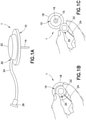
- Fig. 1A illustrates an infusion set 1 for use with an infusion cannula such as a catheter 14.
- the infusion set 1 comprises a fluid connector or hub 22 which is detachably attached to a base (10), a fluid tubing set 24 and a connector 26 which attaches to a pump (not shown).
- Line set 20 includes the hub 22 and the fluid tubing set 24 is attached to or detached from the base 10, as in Figs. 1B and 1C .
- Fig. 1B is a top view of the infusion set 1 with the hub 22 attached to the base 10.
- An adhesive pad 18 is attached to the base 10 and is configured to be attached to the skin of the user.
- Fig. 1C illustrates a view of the infusion set 1 when the line set 20 is detached from the base 10.
- the base 10 includes an infusion adapter 15 to which the catheter 14 is attached.
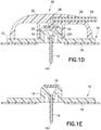
- Fig. 1D is a cross-sectional view of the infusion set 1 and more clearly illustrates how the infusate is pumped into the catheter 14, which is preferably made of a soft plastic material.
- the hub 22 of the line set 20 includes a hub port 29 that receives the fluid tubing set 24.
- the hub 22 includes a flow cannula 23 and a fluid channel 28 positioned between the fluid tubing set 24 and the open tip 231 of the flow cannula 23.
- the base 10 includes a main base portion 12 to which the catheter 14 is secured.
- a pre-slit septum 16 encloses the adapter 15, when the hub 22 is detached from the infusion base 10, as illustrated in Figs. 1C and 1E .
- the flow cannula 24 penetrates the pre-slit septum 16 so that the fluid channel 28 is in fluid communication with the catheter 14. This allows infusate from the pump (not shown) to flow from the fluid tubing set 24 into the fluid channel 28, and into the catheter 14, and the infusate exits the distal opening 141 of the catheter 14 into the patient.
- Infusion cannulas for use in infusion sets and/or patch pumps are manufactured of either rigid material, such as stainless steel, or soft plastic materials, such as fluorinated polymers, including Teflon@. Infusion cannulas may be subject to kinking and occlusion.
- a catheter can kink during or after insertion into a patient when the catheter tube becomes bent due to various causes, resulting in a restricted flow of infusate exiting the catheter. Kinking can be considered to be the cessation of flow through a catheter due to mechanical causes, such as bending of the catheter, sliding back or folding of the catheter on the introducer needle during insertion.
- the restricted flow of the catheter can be caused by kinking and by other causes.
- occlusion is the blockage or cessation of flow due to biological, pharmacological or mechanical causes, including kinking, and these failures typically occur during the use cycle.
- Rigid catheters such as stainless steel cannulas, may have a sharp tip, which is used to pierce the skin, similar to an introducer needle in a conventional inserter. Rigid catheters are recommended for individuals who experience a high incidence of kinking. However, such products are not recommended for use beyond two days, because they can reduce site patency, due to tissue irritation.
- soft plastic catheters such as the catheter 14 illustrated in Fig. 1D
- rigid catheters are often found to be uncomfortable to the user, since they tend to move around within the tissue.
- kinking is considered to be the cessation of flow through a catheter due to mechanical causes. This failure mode can be the result of insufficient interference between the inner diameter of the catheter and the outer diameter of the introducer needle during insertion. In addition, kinking can occur if a blunt distal end of the catheter allows excess force to be transmitted to the catheter as the catheter initially penetrates the outer surface of the skin. Similarly, excessive bounce or vibration in the insertion mechanization may result in excessive force being transmitted to the catheter.
- Kinking can also occur during the infusion or use cycle.
- a typical cause of this failure is the placement of the catheter into tissue which undergoes significant movement during physical activity, which weakens the structure of the catheter, making the catheter less likely to resist mechanical forces that may bend or twist the catheter. Damage that causes deformation of the catheter may also contribute to kinking.
- Flexible catheters are generally more susceptible to kinking than non-flexible catheters.
- the material used in most flexible catheters is a polymer, such as Teflon@. Such material provides flexibility to the catheter.
- Teflon@ a polymer, such as Teflon@.
- Objects of the present invention are to provide a flexible catheter configured and arranged to optimize column strength while maintaining or improving its flexible characteristics and tensile strength, and without adversely affecting its ability to be inserted into and removed from a patient.
- a collapse-resistant catheter comprising:an inner element including alternating thicker segments and thinner segments and one or more indents on the thinner segments; and an outer sleeve covering an outer wall of the inner element;wherein the inner element comprises a swellable material;wherein the outer sleeve comprises a non-swellable material; wherein the inner element is swellable in volume within the outer sleeve upon exposure to liquid, and the thinner segments are folded inwardly at the one or more indents to control a direction of the swelling.
- the improved catheter can be configured to optimize strength to avoid kinking and other undesirable complications, while permitting insulin or other medicaments to be administered via the catheter.
- the improved catheter can replace a conventional catheter without modification of the infusion set, insertion mechanism, or patch pump.
- an exemplary embodiment of the present invention is a catheter 14a that can function in the same manner as the catheter 14 of Figs. 1A and 1D .
- the catheter 14a is composed of (1) a swellable inner tube 100 that is preferably produced from a swellable polymer, and (2) an external, non-swellable outer sleeve 200 that is preferably produced from a non-swellable polymer.
- the swellable inner tube 100 can be replaced by structures other than a tube, as illustrated in Figs. 10A and 10B .
- the non-swellable outer sleeve 200 is sized and shaped like the catheter 14 of Figs. 1A and 1D .
- swellable in this context describes the ability of a material to absorb something, such as a liquid, and to swell in volume or size due to the absorption. Absorption or non-absorption of liquid can be targeted. For instance, one object may not be able to absorb a particular liquid due to its composition and/or configuration, while another object may be able to absorb the same liquid and swell in size or volume. Such properties are effectively utilized in the present invention.
- the swellable inner tube 100 of Figs. 2-7 is preferably produced from a swellable polymer, such as polyurethane. More particularly, a polyurethane product such as Vialon TM biomaterial by Becton, Dickinson and Company (BD) can be used to make the swellable inner tube 100 of Figs. 2-7 or the swellable segments 100b of Figs. 9A and 9B .
- the swellable inner tube 100 will absorb a part of the liquid infusate that is administered via the catheter, that it comes in contact with, to swell its volume. In an infusate containing insulin, Vialon TM biomaterial absorbs the liquid solution in which the insulin is suspended, and not the insulin itself.
- the liquid that is absorbed by the Vialon TM biomaterial is mostly water.
- the amount and rate of swelling of the swellable inner tube 100 can be controlled by formulating its composition and providing various structures to produce the desired characteristics. It is noted that insulin that is administered to a patient is typically in an aqueous solution with water content typically being in excess of 95%, and the water is more readily absorbed by the Vialon TM biomaterial.
- Vialon TM biomaterial can be formulated to control its degree of swelling by absorption of liquid so that it can swell in size or volume by 30% to 300%. Therefore, by careful selection of the material formulation, the amount, volume and rate of swelling of the swellable inner tube 100 can be controlled.
- the maximum swelling of the swellable inner tube 100 is set at approximately 60%, but can be varied for specific uses. Additional disclosures of the exemplary Vialon TM biomaterial can be found in commonly assigned U.S. Patent Nos. 5,226,899 and 5,453,099 to Min-Shiu Lee et al. , U.S. Patent No. 5,545,708 to Theo Onwunaka et al.
- Vialon TM biomaterial polymer provides compatibility with physiologic conditions, and Vialon TM biomaterial polymer has the added advantage of generally not requiring processing additives such as antioxidants and detackifiers that may be extractable and therefore undesirable in biomedical applications.
- Vialon TM biomaterial is a thermoplastic polyurethane, and therefore it can be thermoformed using techniques such as extrusion and injection molding.
- the swellable inner tube 100 and the non-swellable outer sleeve 200 combine to form a catheter 14a that can function similarly to a conventional catheter in the delivery or infusion of insulin. Therefore, the catheter 14a can be substituted for the catheter 14 of Fig. 1D , in an infusion delivery set as illustrated in Figs. 1A-1D , or in a patch pump.
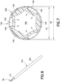
- an introducer needle 50 is inserted into the swellable inner tube 100 of the catheter 14a, as illustrated in Fig. 6 .
- the combined catheter 14a and introducer needle 50 are then inserted into the skin of the patient and the introducer needle 50 is withdrawn while the catheter 14a remains attached to the patient. This is similar to the conventional way of inserting a catheter of an insulin infusion set.
- swellable inner tube 100 may come in contact with the introducer needle 50, but the swellable inner tube 100 is dimensioned so that there will not be excessive interference with the introducer needle 50 to cause damage to the swellable inner tube 50 or to the overall catheter 14a.
- the introducer needle shown in Fig. 6 may be a 27g cannula, which has a diameter of 0.4140 mm (0.0163 in).
- the swellable inner tube 100 is sized and configured to accommodate the 27g cannula.
- the inner diameter of the non-swellable outer sleeve 200 can be 0.6299 mm (0.0248 in)
- the thickness of the thinner segments 140 can be 0.051 mm (0.002 in)
- the thickness of the thicker segments 120 can be 0.102 mm (0.004 in), which will accommodate the introducer needle 50.
- insulin infusion or delivery to the patient via the catheter 14a takes place via the insulin infusion set (as illustrated in Figs. 1A-1D , for example) as desired, required and/or programmed.
- Multiple infusions can take place before the catheter 14a becomes occluded due to some blockage caused by kinking or occlusion, after which the catheter 14a is detached from the patient and discarded.
- Figs. 2-6 represent the catheter 14a as a tubular structure, for ease of explanation, but the end opposite to the distal opening 141 can be shaped to attach to an adapter (as in adapter 15 in Figs. 1C and 1D ).
- the catheter 14a can have the external shape of a conventional catheter.
- catheter 14a includes a swellable inner tube 100.
- swellable inner tube 100 When insulin infusion occurs, insulin is delivered to the patient via the swellable inner tube 100, which, due to its constituent material (e.g. Vialon TM biomaterial), is able to absorb a part of the infusate (mostly water) that is administered to the patient. The amount absorbed is negligible and does not affect the desired insulin therapy, especially since insulin is generally not absorbed.
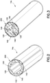
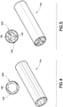
- Figs. 2 and 4 illustrate catheter 14a prior to absorption of any infusate by the swellable inner tube 100. Upon absorption of a part of the infusate, the swellable inner tube 100 swells both inwardly and outwardly, as illustrated in Figs. 3 and 5 . As illustrated in Figs.
- the outward swelling of the swellable inner tube 100 is restrained by the non-swellable outer sleeve 200. Since outward swelling is restrained by the non-swellable outer sleeve 200, the swelling or expansion of the swellable inner tube 100 is directed inward, as illustrated in Fig. 3 , 5 and 8-10 .
- an external, non-swellable outer sleeve 200 is positioned around the swellable tube 100, as illustrated in Figs. 2-7 .
- the external, non-swellable outer sleeve 200 can be made of a material that will not significantly swell by absorption of liquid, such as Teflon@ or similar polymers.
- the non-swellable outer sleeve 200 can be friction-fit, fused or otherwise connected to the swellable inner tube 100 to form the catheter 14a. It is also possible for the swellable inner tube 100 and the non-swellable outer sleeve 200 to be made as a single unit, without assembling the two parts, via a co-extrusion process, for example.
- the non-swellable outer sleeve 200 preferably made of Teflon@, will not significantly absorb liquid that it comes in contact with and will not significantly swell in size.
- the non-swellable outer sleeve 200 acts to restrain the outward swelling or expansion of the swellable inner tube 100, as the swellable inner tube 100 swells upon absorption of liquid of the infusate.
- the non-swellable outer sleeve 200 is configured to have sufficient strength to retain the outward swelling or expansion of the swellable inner tube 100. For example, the strength of the non-swellable outer sleeve 200 can be increased by increasing its thickness.
- the terms “swellable” and “non-swellable” are used in a relative and not absolute sense.
- the non-swellable outer sleeve 200 can experience a small degree of swelling when exposed to infusate or body fluids, or even due to heat, as long as the amount of such swelling is small enough to allow the outer sleeve 200 to restrain the outward swelling of the swellable inner tube 100 as discussed above.
- the outer sleeve 200 can be somewhat swellable as long as it is less swellable than the inner tube 100.
- the inner tube 100 need not be swellable to a great degree as long as it is more swellable than the outer sleeve 200.
- the non-swellable outer sleeve 200 is preferably a thin-walled structure such as Teflon@ shrink tubing with a wall thickness of approximately 0.0127 mm (0.0005 in), which is the difference between the inner diameter D1 and the outer diameter D2 of the non-swellable outer sleeve 200.
- the outer diameter D2 and the inner diameter D1 of the outer sleeve may be 0.660 mm and 0.635 mm (0.026 in and 0.025 in), respectively.
- the non-swellable outer sleeve 200 is configured to restrain the outward expansion of the swellable inner tube 100 and related expansion forces, shown as arrows in Fig. 7 .
- Teflon@ shrink tubing of different thicknesses can be used for the outer sleeve 200.
- Teflon@ shrink tubing is commercially available having a thickness as low as 0.00635 mm (0.00025 in), and such shrink tubing can be used to form the external non-swellable outer sleeve 200.
- infusate containing insulin is pumped into the catheter 14a, and the swellable inner tube 100 beings to swell as liquid of the infusate is absorbed.
- the non-swellable outer sleeve 200 prevents outward swelling or outward expansion of the swellable inner tube 100, from the perspective of the centerline of the catheter 14a, the swelling or expansion of the swellable inner tube 100a is directed inwardly, toward the centerline of the catheter 14a and circumferentially along the inner diameter D1 of the non-swellable outer sleeve 200, in the directions of the arrows of Fig. 7 .
- the direction of swelling of the inner tube 100 can be controlled by configuring the swellable inner tube 100 to include alternating thicker segments 120 and thinner segments 140 and indents 142 on the thinner segments 140, as illustrated in Figs. 2 and 7 .
- the thinner segments 140 become folded inwardly at their respective indents 142, toward the centerline of the catheter 14a to form internal legs 146, as illustrated in Fig. 3 and 5 .
- the formation of the internal legs 146 as the thinner segments 140 and thicker segments 120 swell in size increases the structural strength of the catheter 14a.
- the indents 142 may run along the length of the thinner segments 140, as illustrated in Fig.
- one or more indents may be formed on the inner and/or outer surfaces of the swellable inner tube 100 to control the manner and direction of the swelling of the inner tube 100.
- the swelling or growth of the thicker segments 120 influences the movement and folding of the thinner segments 140 to form the internal legs 146.
- the swelling of the swellable inner tube 100 toward the centerline of the catheter 14a and circumferentially along the inner diameter D1 of the non-swellable outer sleeve 200 is controlled so that the catheter orifice 160 formed along the inner surface of the swellable inner tube 100 remains open in order to permit infusate to be pumped into the catheter 14a.
- the inner tube 100 swells to its maximum size by the absorption of liquid infusate and/or body fluids it comes in contact with, as illustrated in Figs. 3 and 5 , even though the cross-section of the catheter orifice 160 has become reduced, the orifice 160 remains open so that insulin infusion can take place via the swellable inner tube 100, without triggering a blockage or back pressure alarm.
- the cross-section of the swellable inner tube 100 has six segments that resemble a hexagon. There are three thicker segments 120 alternately located between three thinner segments 140. The thinner segments 140 have been further thinned or weakened at specific locations, at indents 142, to control the movement of the segments 120, 140 during swelling, and so that the thinner segments 140 fold inwardly at the indents 142 to form internal legs 146.
- the segments 120, 140 and indents 142 preferably run substantially continuously and uniformly along the length of the swellable inner tube 100.
- a hexagonal arrangement for the swellable inner tube 100 is illustrated, there can be more or less sides, while maintaining the objectives of strengthening the structural integrity of the overall catheter 14a and maintaining a sufficient catheter opening or orifice 160 to permit insulin therapy, as the inner tube 100 swells in size.
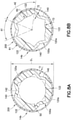
- Fig. 8A and 8B illustrate cross-sectional views of another exemplary catheter.
- Catheter 14b of Figs. 8A and 8B is similar to the catheter 14a of Figs. 2-7 .
- the swellable inner tube 100a of the catheter 14b includes thicker segments 120a each having a concave surface 122 customized to accommodate an outer surface of the introducer needle 50.
- Such an arrangement can accommodate more swellable material in the inner tube 100a, as illustrated in Fig. 8A .
- Parts of the cylindrical outer surface of the introducer needle 50 are received at the reciprocally shaped concave surfaces 122 of the thicker segments 120a, as illustrated in Fig. 8A .
- the thinner segments 140 of the swellable inner tube 100a may also contact the introducer needle 50, as illustrated in Fig. 8A .
- the thinner segments 140 can be made to be sufficiently thin and flexible so that they may be pushed slightly outwardly by the introducer needle 50.
- indents 142 on the thinner segments 140 may be configured to reduce the resistance of the thinner segments 140 to the introducer needle 50.
- Fig. 8B illustrates the catheter 14b without the introducer needle 50.
- Exemplary dimensions for the catheter 14b are provided as follows.
- the outer diameter D1 of the non-swellable outer tube 200 is 0.660 mm (0.026 in)
- the wall thickness T1 of the outer tube 200 is 0.0127 mm (0.0005 in).
- the wall thickness T2 of each of the thinner segments 140 is 0.051 mm (0.002 in), which is further reduced where indents 142 are present.
- the wall thickness of the thicker segments 120 varies as they conform to the inner diameter of the outer sleeve 200 as illustrated in Fig. 8B , but the thickness T3 of the thicker segments 120 is 0.102 mm (0.004 in).
- the radius R1 of its outer wall is 0.305 mm (0.012 in) and the radius R2 of its inner wall is 0.203 mm (0.008 in) at the concave surface 122, which provides a thickness of 0.102 mm (0.004 in).
- the rotational angle A1 of each of the thinner segments 140 can be set at 45 degrees and the rotational angle A2 of each of the thicker segments 120 can be 75 degrees, as illustrated in Fig. 8B to correspond to 60% expansion in the swellable material.
- Figs. 8C, 8D and 8E illustrate a cross-section of the embodiment of Figs. 8A and 8B without showing the non-swellable outer tube 200. However, it is noted that the actual swelling of the inner tube 100a takes place within non-swellable outer sleeve 200.
- Fig. 8C illustrates an initial swelling of the inner tube 100a, after the thinner segments 140 have folded to form the internal legs 146.
- Fig. 8D illustrate the inner tube 100a after it has completely swelled in size and cannot swell any further. In Fig. 8D , the internal legs 146 and the thicker segments 120 have increased in size to reduce the orifice 160.
- Fig. 8D illustrates the swellable inner tube 100a after swelling approximately 60% in size.
- Fig. 8D illustrates the inner tube 100a after maximum absorption of insulin has taken place, while maintaining the opening for the catheter orifice 160 that is sufficient to administer insulin via the swellable inner tube 100a of the catheter 14b.
- the controlled swelling of the swellable inner tube 100a and its interface with the external non-swellable outer sleeve 200 improves the structural integrity of the catheter 14a, 14b and to resist external forces that contribute to catheter collapse, kinking or pinching.
- the swellable inner catheter is made of 60% swellable Vialon TM biomaterial and is shown with a catheter orifice 160 (the area inside the inner tube 100a) having a cross-sectional area C1 of 0.10371592 mm 2 (0.00016076 in 2 ).
- the reduction in cross-sectional area of the catheter orifice 160 is only 42%, and the uncompressed lumen space is much larger than the 0.0155483 mm 2 (0.0000241 in 2 ) cross-sectional area C2 (the area inside the innermost circle) illustrated in Fig. 8E , that would result in the pump pressure increasing to where the pump would trigger an occlusion alarm or cause a loss of infusion therapy.
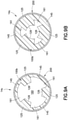
- the inner tube 100b After the swellable inner tube 100b absorbs liquid from the infusate and has swollen in size, as illustrated in Fig. 9B , the inner tube 100b swells in size and catheter orifice 160, including the lateral orifices 161, is reduced in size but remains open.
- the leading surfaces 126 of each of the main swellable segments 125 also increase in size such that they cannot fit into the opposing lateral orifices 161.
- the main swellable segments 125 and the thin connective segments 145 can be thinned or weakened at specific locations to control the motion of expansion or swelling, and/or cause folding, as swellable inner tube 100b swells as liquid from the infusate is absorbed.
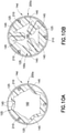
- Figs. 10A and 10B illustrate another exemplary catheter.
- the catheter 14d there is no inner swellable tube. Instead, there are swellable segments 105 made of a swellable material such as Vialon TM biomaterial that are not initially interconnected, as illustrated in Fig. 10A .
- the swellable segments 105 each include a thicker segment 125 and a pair of thin segment legs 145.
- the swellable segments 105 can be attached to the inner walls of the non-swellable outer sleeve 200a by various means.
- the non-swellable outer sleeve 200a includes retention tabs 210 on to which the swellable segments 105 are attached.
- the swellable segments 105 and the outer sleeve 200a having retention tabs 210 can be coextruded to form the catheter 14d and cut to required lengths.
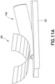
- Fig. 11A illustrates a finite element analysis (FEA) in which the catheter 14b of Fig. 8A was subjected to simulated compression tests to compare the force required to compress the inventive catheter 14b, as compared with a conventional catheter.
- the catheter 14b was placed on a base 92 and a probe 90 was pressed on the catheter 14b at various stages of swelling of the swellable inner tube 100, to view the resistance to the compression by the catheter 14b.
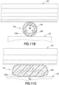
- Fig. 11B illustrates the catheter 14b, with the inner swellable inner tube 100a that has swollen in size such that the cross-sectional area of the catheter orifice 160 has been reduced to about 42% of its original size, prior to compression by the probe 90.
- Fig. 11A finite element analysis
- 11C illustrates the catheter 14b after a set compression force has been applied.
- the thickened walls of the swellable inner tube 100 due to swelling, and the configuration of the components thereof, such as the thicker and thinner segments 120a, 140 and the formation of the internal legs 146, resisted total collapse and maintained an opening of the catheter orifice 160 sufficient to administer insulin therapy.
- the force required to pinch to a minimum area before an occlusion alarm can be triggered for the conventional catheter 22 was 0.151 kg (0.334 lb), while the force required to pinch to a minimum area for the inventive catheter 14b was 0.299 kg (0.660 lb).
- a one-part swellable inner tube 100, 100a can be produced from a continuous extrusion process that is well known in the art.
- the external non-swellable outer sleeve 200 can also be produced from a continuous extrusion process.
- the external non-swellable outer sleeve 200 can be produced from a medical grade Teflon@ shrink tubing that can be manufactured with an inner diameter slightly larger than the outer diameter of the swellable inner tube 100, 100a, in order to allow the two pieces to be assembled together to allow a slip-fit assembly of the catheter 14a, 14b.
- the entire non-swellable outer sleeve 200 can be shrunk in diameter, or just the lead end of the non-swellable outer sleeve 200 can be shrunk in diameter, to bind the two components to form the catheter 14a, 14b. Thereafter, the two-part assembly can be completed by Radio Frequency (RF) tipping to further bond the lead end of the external non-swellable outer sleeve 200 to the swellable inner tube 100, 100a.
- RF Radio Frequency
- the swellable inner tube 100, 100a can be molded to a finished length and tip dimensions, and the external non-swellable outer sleeve 200 can be attached as described above.
- a similar process can form the catheter 14d of Figs. 10A and 10B .
- the swellable inner tube 100, 100a, 100b and the swellable segments 105 can be co-extruded or two-shot molded, and the external non-swellable outer sleeve 200 can be attached to the swellable tube 100, 100a, 100b or swellable segments 105 by the methods described above.
- the composite catheter 14c of Figs. 9A and 9B can be composed of a non-swellable sleeve that is over-molded or co-extruded with segments of swellable polymer.
- the inventive catheter After the swellable inner tube 100a becomes swollen, the overall structure of the catheter 14b is able to resist or minimize kinking, because the internal legs 146 that are formed as a result of the material swelling resist total collapse of the overall structure. At the same time, the flow of insulin is possible through the catheter orifice 160. Even though the cross-section of the catheter orifice 160 is reduced due to material swelling, a sufficient opening is maintained, such that the required pump pressure will not exceed the normal flow conditions of the pump and trigger an occlusion alarm.
- inventive kink-resistant catheter 14b is potentially less expensive to produce than other anti-kinking catheter structures, such as in-dwelling flexible stainless steel needles or partially retracting introducer needles. Such alternative stainless steel needles are more rigid and can cause greater discomfort to the patient.
- Another advantage of the inventive device is that the overall dimensions and gauge sizes of the collapse-resistant catheter 14b, including the swellable inner tube 100a and the non-swellable outer sleeve 200, conform to the gauge sizes currently used for insulin infusion, such as a 24 gauge introducer needle and a 27 gauge catheter.
- the catheter 14b can be substituted for a conventional catheter used in insulin infusion sets, without major modification.
- the advantages mentioned above, with regard to catheter 14b can generally be said of catheters 14a, 14c and 14d, as well.
Landscapes
- Health & Medical Sciences (AREA)
- Life Sciences & Earth Sciences (AREA)
- Animal Behavior & Ethology (AREA)
- Veterinary Medicine (AREA)
- Public Health (AREA)
- General Health & Medical Sciences (AREA)
- Engineering & Computer Science (AREA)
- Heart & Thoracic Surgery (AREA)
- Hematology (AREA)
- Biomedical Technology (AREA)
- Anesthesiology (AREA)
- Pulmonology (AREA)
- Biophysics (AREA)
- Vascular Medicine (AREA)
- Dermatology (AREA)
- Chemical & Material Sciences (AREA)
- Chemical Kinetics & Catalysis (AREA)
- Epidemiology (AREA)
- Infusion, Injection, And Reservoir Apparatuses (AREA)
Claims (10)
- Kollabierresistenter Katheter (14), der aufweist:ein Innenelement (100), das abwechselnd dickere Segmente und dünnere Segmente und eine oder mehreren Kerben auf den dünneren Segmenten aufweist; undeine Außenhülse (200), die eine Außenwand des Innenelements (100) bedeckt;wobei das Innenelement (100) ein quellfähiges Material aufweist;wobei die Außenhülse (200) ein nicht quellfähiges Material aufweist;dadurch gekennzeichnet, dassdas Innenelement (100) in der Außenhülse (200) bei Einwirkung von Flüssigkeit im Volumen quellfähig ist und die dünneren Segmente an der einen oderden mehreren Kerben nach innen geklappt sind, um eine Quellrichtung zu steuern.
- Katheter (14) nach Anspruch 1, wobei das Quellen des Innenelements (100) nach außen durch die nicht quellfähige Außenhülse (200) begrenzt wird.
- Katheter (14) nach Anspruch 1, wobei das Quellen des Innenelements (100) nach innen zu dessen Mittellinie gerichtet ist.
- Katheter (14) nach Anspruch 1, wobei die Öffnung des Katheters (14) so bemessen ist, dass sie eine Einführnadel (50) aufnehmen kann.
- Katheter (14) nach Anspruch 1, wobei das quellfähige Material des Innenelements (100) ein quellfähiges Polymer aufweist oder das Quellen des Innenelements (100) durch die Polymerzusammensetzung gesteuert wird.
- Katheter nach Anspruch 1, wobei jedes der ein oder mehreren dünnen Segmente (140) so ausgebildet ist, dass es zur Mittellinie des Katheters (14) kollabiert, wenn Flüssigkeit absorbiert wird.
- Katheter (14) nach Anspruch 1, wobei jedes der kollabierten dünnen Segmente (140) ein Stützbein (146) bildet.
- Katheter nach Anspruch 1, wobei die Außenhülse (200) eine oder mehrere Rückhaltelaschen aufweist, an denen das eine oder die mehreren dicken Segmente (120) und das eine oder die mehreren dünnen Segmente (140) befestigt sind.
- Verfahren zur Herstellung eines kollabierresistenten Katheters (14), das die folgenden Schritte umfasst:Bilden eines Innenelements (100), das abwechselnd dickere Segmente unddünnere Segmente und eine oder mehreren Kerben auf den dünneren Segmenten durch Extrudieren eines quellfähigen Materials aufweist; undBilden einer Außenhülse (200) durch Extrudieren eines nicht quellfähigen Materials;Einsetzen des Innenelements (100) in die Außenhülse (200); gekennzeichnet durchSchrumpfen der Außenhülse (200) über das Innenelement (100), um den kollabierresistenten Katheter (14) zu bilden, wobei, wenn das Innenelement (100) Flüssigkeit absorbiert, das Innenelement (100) quillt und die dünneren Segmente an der einen oder den mehreren Kerben nach innen klappen, um eine Quellrichtung zu steuern.
- Verfahren nach Anspruch 9, das ferner den Schritt zum Bonden der Außenhülse (200) am Innenelement (100) durch RF-Kippung umfasst.
Applications Claiming Priority (2)
| Application Number | Priority Date | Filing Date | Title |
|---|---|---|---|
| US13/479,114 US10220186B2 (en) | 2012-05-23 | 2012-05-23 | Collapse-resistant swellable catheter |
| PCT/US2013/038890 WO2013176850A1 (en) | 2012-05-23 | 2013-04-30 | Collapse-resistant swellable catheter |
Publications (3)
| Publication Number | Publication Date |
|---|---|
| EP2852420A1 EP2852420A1 (de) | 2015-04-01 |
| EP2852420A4 EP2852420A4 (de) | 2016-05-11 |
| EP2852420B1 true EP2852420B1 (de) | 2022-02-23 |
Family
ID=49622164
Family Applications (1)
| Application Number | Title | Priority Date | Filing Date |
|---|---|---|---|
| EP13794584.6A Active EP2852420B1 (de) | 2012-05-23 | 2013-04-30 | Kollapsresistenter quellbarer katheter |
Country Status (7)
| Country | Link |
|---|---|
| US (2) | US10220186B2 (de) |
| EP (1) | EP2852420B1 (de) |
| JP (1) | JP6375292B2 (de) |
| CN (2) | CN203634622U (de) |
| CA (1) | CA2872766C (de) |
| ES (1) | ES2908880T3 (de) |
| WO (1) | WO2013176850A1 (de) |
Families Citing this family (23)
| Publication number | Priority date | Publication date | Assignee | Title |
|---|---|---|---|---|
| US8202248B2 (en) | 2004-08-18 | 2012-06-19 | Sequana Medical Ag | Dialysis implant and methods of use |
| US8585635B2 (en) | 2012-02-15 | 2013-11-19 | Sequana Medical Ag | Systems and methods for treating chronic liver failure based on peritoneal dialysis |
| US10213533B2 (en) * | 2012-03-05 | 2019-02-26 | Keith A. Walter | Medical tools with aspiration tips suitable for cataract surgeries and related methods |
| US10220186B2 (en) * | 2012-05-23 | 2019-03-05 | Becton, Dickinson And Company | Collapse-resistant swellable catheter |
| US9144660B2 (en) | 2012-10-31 | 2015-09-29 | Sequana Medical Ag | Implantable catheters with staggered slits, and methods of using same |
| USD743542S1 (en) * | 2012-10-31 | 2015-11-17 | Sequana Medical Ag | Catheter with staggered slits |
| USD743543S1 (en) * | 2012-10-31 | 2015-11-17 | Sequana Medical Ag | Catheter with staggered slits |
| CN103893901A (zh) * | 2014-03-24 | 2014-07-02 | 苏州新区明基高分子医疗器械有限公司 | 一种防压引流管 |
| EP3132822B1 (de) * | 2014-04-14 | 2018-10-31 | Toppan Printing Co., Ltd. | Injektionsvorrichtung |
| EP3042684B1 (de) | 2015-01-07 | 2026-04-29 | Abiomed Europe GmbH | Einführschleusen-Set |
| US12194256B2 (en) * | 2015-04-10 | 2025-01-14 | Edwards Lifesciences Corporation | Expandable sheath |
| CN104901241A (zh) * | 2015-04-22 | 2015-09-09 | 吴申龙 | 一种收缩管道 |
| US20170095641A1 (en) * | 2015-10-06 | 2017-04-06 | Covidien Lp | Catheter with curvilinear polygon cross-sectional shape |
| JP7071338B2 (ja) | 2016-08-26 | 2022-05-18 | セクアナ メディカル エヌブイ | 埋め込み型装置によって生成されたデータを管理及び分析するためのシステム及び方法 |
| US10821225B2 (en) * | 2017-01-20 | 2020-11-03 | Medtronic Minimed, Inc. | Cannulas for drug delivery devices |
| US10918778B2 (en) | 2017-05-24 | 2021-02-16 | Sequana Medical Nv | Direct sodium removal method, solution and apparatus to reduce fluid overload in heart failure patients |
| US11559618B2 (en) | 2017-05-24 | 2023-01-24 | Sequana Medical Nv | Formulations and methods for direct sodium removal in patients having severe renal dysfunction |
| US20190054270A1 (en) * | 2017-08-15 | 2019-02-21 | Becton, Dickinson And Company | Anti-occlusion catheter |
| CN108057166A (zh) * | 2017-12-11 | 2018-05-22 | 陈永忠 | 医用可调节器械鞘 |
| CN108434549A (zh) * | 2018-03-30 | 2018-08-24 | 陶霞霞 | 一种输液留置针 |
| US20210128037A1 (en) * | 2019-10-30 | 2021-05-06 | Becton, Dickinson And Company | Blood collection system with user-adjusted pressure management and related methods |
| USD982427S1 (en) * | 2020-01-08 | 2023-04-04 | Art Guild, Inc. | Elongated tube |
| DE102020105522A1 (de) * | 2020-03-02 | 2021-09-02 | Tracoe Medical Gmbh | Trachealbeatmungsvorrichtung mit optimiertem Cuff-Schlauch |
Family Cites Families (85)
| Publication number | Priority date | Publication date | Assignee | Title |
|---|---|---|---|---|
| US3545443A (en) * | 1968-09-26 | 1970-12-08 | Amir H Ansari | Suprapubic cystostomy needle |
| US4044119A (en) * | 1973-05-03 | 1977-08-23 | Cutter Laboratories, Inc. | Method of controlling release of medicament and bolus therefor |
| US4141364A (en) * | 1977-03-18 | 1979-02-27 | Jorge Schultze | Expandable endotracheal or urethral tube |
| US4401433A (en) * | 1980-06-13 | 1983-08-30 | Luther Ronald B | Apparatus for advancing oversized catheter through cannula, and the like |
| US4406656A (en) * | 1981-06-01 | 1983-09-27 | Brack Gillium Hattler | Venous catheter having collapsible multi-lumens |
| US4548205A (en) * | 1982-10-27 | 1985-10-22 | Armeniades C D | Ophthalmic instrument for measuring intraocular fluid pressure |
| US4808154A (en) * | 1983-10-26 | 1989-02-28 | Freeman Jerre M | Phacoemulsification/irrigation and aspiration sleeve apparatus |
| WO1986001813A1 (en) * | 1984-09-21 | 1986-03-27 | Raychem Corporation | Multiple phase polymeric compositions |
| US4883699A (en) * | 1984-09-21 | 1989-11-28 | Menlo Care, Inc. | Polymeric article having high tensile energy to break when hydrated |
| US4710181A (en) * | 1985-06-11 | 1987-12-01 | Genus Catheter Technologies, Inc. | Variable diameter catheter |
| US4601713A (en) * | 1985-06-11 | 1986-07-22 | Genus Catheter Technologies, Inc. | Variable diameter catheter |
| US4693249A (en) * | 1986-01-10 | 1987-09-15 | Schenck Robert R | Anastomosis device and method |
| US4681561A (en) * | 1986-01-24 | 1987-07-21 | Coopervision, Inc. | Ultrasonic decoupling sleeve |
| US4776846A (en) * | 1987-02-06 | 1988-10-11 | Becton, Dickinson And Company | Splittable catheter composite material and process |
| US4840622A (en) | 1987-10-06 | 1989-06-20 | Menlo Care, Inc. | Kink resistant catheter |
| US4840623A (en) * | 1988-02-01 | 1989-06-20 | Fbk International Corporation | Medical catheter with splined internal wall |
| US4935017A (en) * | 1988-04-29 | 1990-06-19 | C. R. Bard, Inc. | Variable shaped catheter system and method for catheterization |
| US4994047A (en) | 1988-05-06 | 1991-02-19 | Menlo Care, Inc. | Multi-layer cannula structure |
| US4954129A (en) * | 1988-07-25 | 1990-09-04 | Abbott Laboratories | Hydrodynamic clot flushing |
| US5226899A (en) | 1990-03-26 | 1993-07-13 | Becton, Dickinson And Company | Catheter tubing of controlled in vivo softening |
| US5453099A (en) | 1990-03-26 | 1995-09-26 | Becton, Dickinson And Company | Catheter tubing of controlled in vivo softening |
| US5112301A (en) * | 1991-06-19 | 1992-05-12 | Strato Medical Corporation | Bidirectional check valve catheter |
| US5215527A (en) | 1991-12-12 | 1993-06-01 | Becton, Dickinson And Company | Catheter introducer assembly |
| US5478328A (en) * | 1992-05-22 | 1995-12-26 | Silverman; David G. | Methods of minimizing disease transmission by used hypodermic needles, and hypodermic needles adapted for carrying out the method |
| EP0598867B1 (de) * | 1992-06-15 | 1997-03-05 | WYSSMANN, Max | Vorrichtung zur gezielten, steuerbaren abgabe einer flüssigkeit oder einer viskosen masse |
| US6623516B2 (en) * | 1992-08-13 | 2003-09-23 | Mark A. Saab | Method for changing the temperature of a selected body region |
| US5674240A (en) * | 1993-02-04 | 1997-10-07 | Peter M. Bonutti | Expandable cannula |
| US5545708A (en) | 1993-07-14 | 1996-08-13 | Becton, Dickinson And Company | Thermoplastic polyurethane method of making same and forming a medical article therefrom |
| JPH0793944A (ja) | 1993-09-22 | 1995-04-07 | Hitachi Ltd | カセットカートリッジ |
| US5599306A (en) * | 1994-04-01 | 1997-02-04 | Localmed, Inc. | Method and apparatus for providing external perfusion lumens on balloon catheters |
| US5553625A (en) * | 1994-12-07 | 1996-09-10 | Imaging And Display Systems Technology, Inc. | Intravenous blood sampling needle and intravenous therapy |
| US5505693A (en) * | 1994-12-30 | 1996-04-09 | Mackool; Richard J. | Method and apparatus for reducing friction and heat generation by an ultrasonic device during surgery |
| IE77523B1 (en) * | 1995-09-11 | 1997-12-17 | Elan Med Tech | Medicament delivery device |
| US5772629A (en) * | 1995-10-23 | 1998-06-30 | Localmed, Inc. | Localized intravascular delivery of TFPI for inhibition of restenosis in recanalized blood vessels |
| US5840008A (en) * | 1995-11-13 | 1998-11-24 | Localmed, Inc. | Radiation emitting sleeve catheter and methods |
| US5817099A (en) * | 1996-06-06 | 1998-10-06 | Skolik; Stephanie A. | Universal port/seal device for ocular surgery |
| US5971959A (en) * | 1998-06-03 | 1999-10-26 | Liu; Wen-Neng | Automatic safety infusion catheter needle |
| US6106515A (en) * | 1998-08-13 | 2000-08-22 | Intraluminal Therapeutics, Inc. | Expandable laser catheter |
| US6165158A (en) | 1998-10-14 | 2000-12-26 | Advanced Cardiovascular Systems, Inc. | Lubricious catheter shaft |
| US6749589B1 (en) | 2000-01-18 | 2004-06-15 | Sterling Medications, Inc. | Subcutaneous injection set for use with a reservoir that has a septum |
| US6743206B1 (en) * | 2000-03-07 | 2004-06-01 | Syntheon, Llc | Endoscopic needle |
| ATE395939T1 (de) * | 2001-04-02 | 2008-06-15 | Bladder Man Systems Llc | Anpassbarer ballonloser katheder |
| US6632217B2 (en) * | 2001-04-19 | 2003-10-14 | Microsolutions, Inc. | Implantable osmotic pump |
| WO2004037333A1 (en) | 2002-10-25 | 2004-05-06 | Nmt Medical, Inc. | Expandable sheath tubing |
| WO2005032642A2 (en) * | 2003-10-03 | 2005-04-14 | Acumen Medical, Inc. | Expandable guide sheath and apparatus and methods for making them |
| US7780692B2 (en) * | 2003-12-05 | 2010-08-24 | Onset Medical Corporation | Expandable percutaneous sheath |
| US7494472B2 (en) * | 2003-12-23 | 2009-02-24 | Windy Hill Medical, Inc. | Ductal lavage catheter having an off-axis tip |
| US7465286B2 (en) * | 2004-03-03 | 2008-12-16 | C. R. Bard, Inc. | Loop-tip catheter |
| US20050226814A1 (en) * | 2004-04-13 | 2005-10-13 | Bausch & Lomb Incorporated | Diagnostic method and kit for implantation of a sustained release drug-delivery implant with a steroid |
| US7452351B2 (en) * | 2004-04-16 | 2008-11-18 | Kyphon Sarl | Spinal diagnostic methods and apparatus |
| US7785318B2 (en) | 2004-05-27 | 2010-08-31 | Abbott Laboratories | Catheter having plurality of stiffening members |
| US7601136B2 (en) * | 2004-07-20 | 2009-10-13 | Takayuki Akahoshi | Infusion sleeve |
| US7892203B2 (en) * | 2004-09-09 | 2011-02-22 | Onset Medical Corporation | Expandable transluminal sheath |
| US20060135962A1 (en) * | 2004-09-09 | 2006-06-22 | Kick George F | Expandable trans-septal sheath |
| US7875049B2 (en) * | 2004-10-04 | 2011-01-25 | Medtronic, Inc. | Expandable guide sheath with steerable backbone and methods for making and using them |
| EP1841476B1 (de) * | 2005-01-17 | 2011-06-29 | Novo Nordisk A/S | Flüssigkeitsausgabevorrichtung mit integrierter überwachung von physiologischen eigenschaften |
| US20070021648A1 (en) * | 2005-06-29 | 2007-01-25 | Jay Lenker | Transluminal sheath hub |
| US7766906B2 (en) * | 2005-08-19 | 2010-08-03 | Boston Scientific Scimed, Inc. | Occlusion apparatus |
| US7637902B2 (en) * | 2005-11-23 | 2009-12-29 | Medtronic, Inc. | Slittable and peelable sheaths and methods for making and using them |
| DE602006006477D1 (de) * | 2005-12-23 | 2009-06-04 | Unomedical As | Verabreichungsgerät |
| US7892216B2 (en) * | 2006-02-07 | 2011-02-22 | Icu Medical, Inc. | Infusion set |
| EP2319558B1 (de) * | 2006-03-14 | 2014-05-21 | University Of Southern California | Mems-Vorrichtung zur Wirkstofffreisetzung |
| US7678223B2 (en) | 2006-04-17 | 2010-03-16 | Boston Scientific Scimed, Inc. | Catheter having a multi-section tubular member and method of making the same |
| SE532670C2 (sv) | 2006-04-19 | 2010-03-16 | Nordic Med Com Ab | Kateteraggregat |
| US7905877B1 (en) | 2006-05-12 | 2011-03-15 | Micrus Design Technology, Inc. | Double helix reinforced catheter |
| TWI498136B (zh) * | 2007-10-09 | 2015-09-01 | Alcon Res Ltd | 用於遞送速率及溫度相依性物質至眼睛的注射器及其製備方法 |
| ITMI20072309A1 (it) * | 2007-12-10 | 2009-06-11 | N G C Medical S P A | Tubo presentante un diametro allargabile, particolarmente utilizzabile come tubo per introduttore vasale durante studi emodinamici ed interventi relativi. |
| US8668668B2 (en) * | 2008-05-14 | 2014-03-11 | Onset Medical Corporation | Expandable iliac sheath and method of use |
| US8690936B2 (en) * | 2008-10-10 | 2014-04-08 | Edwards Lifesciences Corporation | Expandable sheath for introducing an endovascular delivery device into a body |
| US8790387B2 (en) * | 2008-10-10 | 2014-07-29 | Edwards Lifesciences Corporation | Expandable sheath for introducing an endovascular delivery device into a body |
| US9375529B2 (en) | 2009-09-02 | 2016-06-28 | Becton, Dickinson And Company | Extended use medical device |
| CA2993719C (en) | 2009-01-12 | 2022-04-19 | Becton, Dickinson And Company | Infusion set and/or patch pump having at least one of an in-dwelling rigid catheter with flexible features and/or a flexible catheter attachment |
| AU2010231527A1 (en) | 2009-03-30 | 2011-11-03 | F.Hoffmann-La Roche Ag | Devices and methods for enhancing drug absorption rate |
| US7806865B1 (en) * | 2009-05-20 | 2010-10-05 | Alcon Research, Ltd. | Pressurized irrigation squeeze band |
| US8100881B2 (en) * | 2009-08-04 | 2012-01-24 | Cook Medical Technologies Llc | Flexible medical device for clot removal from small vessels |
| US10092691B2 (en) | 2009-09-02 | 2018-10-09 | Becton, Dickinson And Company | Flexible and conformal patch pump |
| US20110137231A1 (en) * | 2009-12-08 | 2011-06-09 | Alcon Research, Ltd. | Phacoemulsification Hand Piece With Integrated Aspiration Pump |
| US8070711B2 (en) * | 2009-12-09 | 2011-12-06 | Alcon Research, Ltd. | Thermal management algorithm for phacoemulsification system |
| WO2011081001A1 (ja) | 2009-12-28 | 2011-07-07 | テルモ株式会社 | バルーンカテーテル |
| US8784357B2 (en) * | 2010-09-15 | 2014-07-22 | Alcon Research, Ltd. | Phacoemulsification hand piece with two independent transducers |
| CN103260559B (zh) * | 2010-12-15 | 2016-01-06 | 爱尔康研究有限公司 | 具有多个材料层的输注套筒 |
| US8475480B2 (en) * | 2011-01-04 | 2013-07-02 | Alcon Research Ltd | Multi-sleeved surgical ultrasonic vibrating tool suited for phacoemulsification in a manner that prevents thermal injury to ocular tissue |
| WO2012108954A2 (en) * | 2011-02-09 | 2012-08-16 | Becton, Dickinson And Company | Nighttime basal dosing device |
| US8414605B2 (en) * | 2011-07-08 | 2013-04-09 | Alcon Research, Ltd. | Vacuum level control of power for phacoemulsification hand piece |
| US10220186B2 (en) * | 2012-05-23 | 2019-03-05 | Becton, Dickinson And Company | Collapse-resistant swellable catheter |
-
2012
- 2012-05-23 US US13/479,114 patent/US10220186B2/en active Active
-
2013
- 2013-04-30 EP EP13794584.6A patent/EP2852420B1/de active Active
- 2013-04-30 JP JP2015514035A patent/JP6375292B2/ja active Active
- 2013-04-30 WO PCT/US2013/038890 patent/WO2013176850A1/en not_active Ceased
- 2013-04-30 ES ES13794584T patent/ES2908880T3/es active Active
- 2013-04-30 CA CA2872766A patent/CA2872766C/en active Active
- 2013-05-23 CN CN201320284478.2U patent/CN203634622U/zh not_active Expired - Lifetime
- 2013-05-23 CN CN201310193458.9A patent/CN103418071B/zh active Active
-
2019
- 2019-01-18 US US16/251,494 patent/US11123520B2/en active Active
Also Published As
| Publication number | Publication date |
|---|---|
| CA2872766C (en) | 2021-06-22 |
| US20190151611A1 (en) | 2019-05-23 |
| EP2852420A4 (de) | 2016-05-11 |
| JP6375292B2 (ja) | 2018-08-15 |
| CN203634622U (zh) | 2014-06-11 |
| US11123520B2 (en) | 2021-09-21 |
| ES2908880T3 (es) | 2022-05-04 |
| EP2852420A1 (de) | 2015-04-01 |
| CA2872766A1 (en) | 2013-11-28 |
| CN103418071B (zh) | 2018-12-21 |
| US20130317476A1 (en) | 2013-11-28 |
| CN103418071A (zh) | 2013-12-04 |
| WO2013176850A1 (en) | 2013-11-28 |
| US10220186B2 (en) | 2019-03-05 |
| JP2015517384A (ja) | 2015-06-22 |
Similar Documents
| Publication | Publication Date | Title |
|---|---|---|
| US11123520B2 (en) | Collapse-resistant swellable catheter | |
| JP7401477B2 (ja) | カテーテルを備えた注入装置及びカテーテルを作る方法 | |
| JP2020185459A (ja) | 注入システム | |
| JP5575830B2 (ja) | 互い違いの内腔を有するカテーテルおよび方法 | |
| JP2006514873A (ja) | 可撓性の注射針 | |
| WO2008137353A1 (en) | Offset catheter connector, system and method for use | |
| US20250009962A1 (en) | Flexible cannula and process | |
| EP1628700B1 (de) | Hochdruckkatheter und herstellungsverfahren dafür | |
| CA3049716C (en) | Cannulas for drug delivery devices | |
| AU2021397261A1 (en) | Squeezable subcutaneous port | |
| CN223504299U (zh) | 一种骶管麻醉穿刺留置套件 | |
| WO2016016419A1 (en) | Needle tube and method of producing injection needles | |
| NZ621749B2 (en) | A catheter having a pressure activated splittable feature |
Legal Events
| Date | Code | Title | Description |
|---|---|---|---|
| PUAI | Public reference made under article 153(3) epc to a published international application that has entered the european phase |
Free format text: ORIGINAL CODE: 0009012 |
|
| 17P | Request for examination filed |
Effective date: 20141111 |
|
| AK | Designated contracting states |
Kind code of ref document: A1 Designated state(s): AL AT BE BG CH CY CZ DE DK EE ES FI FR GB GR HR HU IE IS IT LI LT LU LV MC MK MT NL NO PL PT RO RS SE SI SK SM TR |
|
| AX | Request for extension of the european patent |
Extension state: BA ME |
|
| DAX | Request for extension of the european patent (deleted) | ||
| RA4 | Supplementary search report drawn up and despatched (corrected) |
Effective date: 20160408 |
|
| RIC1 | Information provided on ipc code assigned before grant |
Ipc: A61M 25/00 20060101AFI20160404BHEP |
|
| RAP1 | Party data changed (applicant data changed or rights of an application transferred) |
Owner name: BECTON, DICKINSON AND COMPANY |
|
| STAA | Information on the status of an ep patent application or granted ep patent |
Free format text: STATUS: EXAMINATION IS IN PROGRESS |
|
| 17Q | First examination report despatched |
Effective date: 20190304 |
|
| REG | Reference to a national code |
Ref country code: DE Ref legal event code: R079 Ref document number: 602013080983 Country of ref document: DE Free format text: PREVIOUS MAIN CLASS: A61M0005000000 Ipc: A61M0025000000 |
|
| RIC1 | Information provided on ipc code assigned before grant |
Ipc: A61M 25/00 20060101AFI20190716BHEP Ipc: A61M 5/142 20060101ALI20190716BHEP Ipc: A61L 29/06 20060101ALI20190716BHEP |
|
| GRAP | Despatch of communication of intention to grant a patent |
Free format text: ORIGINAL CODE: EPIDOSNIGR1 |
|
| STAA | Information on the status of an ep patent application or granted ep patent |
Free format text: STATUS: GRANT OF PATENT IS INTENDED |
|
| INTG | Intention to grant announced |
Effective date: 20210923 |
|
| GRAS | Grant fee paid |
Free format text: ORIGINAL CODE: EPIDOSNIGR3 |
|
| GRAA | (expected) grant |
Free format text: ORIGINAL CODE: 0009210 |
|
| STAA | Information on the status of an ep patent application or granted ep patent |
Free format text: STATUS: THE PATENT HAS BEEN GRANTED |
|
| AK | Designated contracting states |
Kind code of ref document: B1 Designated state(s): AL AT BE BG CH CY CZ DE DK EE ES FI FR GB GR HR HU IE IS IT LI LT LU LV MC MK MT NL NO PL PT RO RS SE SI SK SM TR |
|
| REG | Reference to a national code |
Ref country code: GB Ref legal event code: FG4D |
|
| REG | Reference to a national code |
Ref country code: CH Ref legal event code: EP |
|
| REG | Reference to a national code |
Ref country code: DE Ref legal event code: R096 Ref document number: 602013080983 Country of ref document: DE |
|
| REG | Reference to a national code |
Ref country code: AT Ref legal event code: REF Ref document number: 1469958 Country of ref document: AT Kind code of ref document: T Effective date: 20220315 |
|
| REG | Reference to a national code |
Ref country code: IE Ref legal event code: FG4D |
|
| REG | Reference to a national code |
Ref country code: ES Ref legal event code: FG2A Ref document number: 2908880 Country of ref document: ES Kind code of ref document: T3 Effective date: 20220504 |
|
| REG | Reference to a national code |
Ref country code: LT Ref legal event code: MG9D |
|
| REG | Reference to a national code |
Ref country code: NL Ref legal event code: MP Effective date: 20220223 |
|
| REG | Reference to a national code |
Ref country code: AT Ref legal event code: MK05 Ref document number: 1469958 Country of ref document: AT Kind code of ref document: T Effective date: 20220223 |
|
| PG25 | Lapsed in a contracting state [announced via postgrant information from national office to epo] |
Ref country code: SE Free format text: LAPSE BECAUSE OF FAILURE TO SUBMIT A TRANSLATION OF THE DESCRIPTION OR TO PAY THE FEE WITHIN THE PRESCRIBED TIME-LIMIT Effective date: 20220223 Ref country code: RS Free format text: LAPSE BECAUSE OF FAILURE TO SUBMIT A TRANSLATION OF THE DESCRIPTION OR TO PAY THE FEE WITHIN THE PRESCRIBED TIME-LIMIT Effective date: 20220223 Ref country code: PT Free format text: LAPSE BECAUSE OF FAILURE TO SUBMIT A TRANSLATION OF THE DESCRIPTION OR TO PAY THE FEE WITHIN THE PRESCRIBED TIME-LIMIT Effective date: 20220623 Ref country code: NO Free format text: LAPSE BECAUSE OF FAILURE TO SUBMIT A TRANSLATION OF THE DESCRIPTION OR TO PAY THE FEE WITHIN THE PRESCRIBED TIME-LIMIT Effective date: 20220523 Ref country code: NL Free format text: LAPSE BECAUSE OF FAILURE TO SUBMIT A TRANSLATION OF THE DESCRIPTION OR TO PAY THE FEE WITHIN THE PRESCRIBED TIME-LIMIT Effective date: 20220223 Ref country code: LT Free format text: LAPSE BECAUSE OF FAILURE TO SUBMIT A TRANSLATION OF THE DESCRIPTION OR TO PAY THE FEE WITHIN THE PRESCRIBED TIME-LIMIT Effective date: 20220223 Ref country code: HR Free format text: LAPSE BECAUSE OF FAILURE TO SUBMIT A TRANSLATION OF THE DESCRIPTION OR TO PAY THE FEE WITHIN THE PRESCRIBED TIME-LIMIT Effective date: 20220223 Ref country code: BG Free format text: LAPSE BECAUSE OF FAILURE TO SUBMIT A TRANSLATION OF THE DESCRIPTION OR TO PAY THE FEE WITHIN THE PRESCRIBED TIME-LIMIT Effective date: 20220523 |
|
| PG25 | Lapsed in a contracting state [announced via postgrant information from national office to epo] |
Ref country code: PL Free format text: LAPSE BECAUSE OF FAILURE TO SUBMIT A TRANSLATION OF THE DESCRIPTION OR TO PAY THE FEE WITHIN THE PRESCRIBED TIME-LIMIT Effective date: 20220223 Ref country code: LV Free format text: LAPSE BECAUSE OF FAILURE TO SUBMIT A TRANSLATION OF THE DESCRIPTION OR TO PAY THE FEE WITHIN THE PRESCRIBED TIME-LIMIT Effective date: 20220223 Ref country code: GR Free format text: LAPSE BECAUSE OF FAILURE TO SUBMIT A TRANSLATION OF THE DESCRIPTION OR TO PAY THE FEE WITHIN THE PRESCRIBED TIME-LIMIT Effective date: 20220524 Ref country code: FI Free format text: LAPSE BECAUSE OF FAILURE TO SUBMIT A TRANSLATION OF THE DESCRIPTION OR TO PAY THE FEE WITHIN THE PRESCRIBED TIME-LIMIT Effective date: 20220223 Ref country code: AT Free format text: LAPSE BECAUSE OF FAILURE TO SUBMIT A TRANSLATION OF THE DESCRIPTION OR TO PAY THE FEE WITHIN THE PRESCRIBED TIME-LIMIT Effective date: 20220223 |
|
| PG25 | Lapsed in a contracting state [announced via postgrant information from national office to epo] |
Ref country code: IS Free format text: LAPSE BECAUSE OF FAILURE TO SUBMIT A TRANSLATION OF THE DESCRIPTION OR TO PAY THE FEE WITHIN THE PRESCRIBED TIME-LIMIT Effective date: 20220623 |
|
| PG25 | Lapsed in a contracting state [announced via postgrant information from national office to epo] |
Ref country code: SM Free format text: LAPSE BECAUSE OF FAILURE TO SUBMIT A TRANSLATION OF THE DESCRIPTION OR TO PAY THE FEE WITHIN THE PRESCRIBED TIME-LIMIT Effective date: 20220223 Ref country code: SK Free format text: LAPSE BECAUSE OF FAILURE TO SUBMIT A TRANSLATION OF THE DESCRIPTION OR TO PAY THE FEE WITHIN THE PRESCRIBED TIME-LIMIT Effective date: 20220223 Ref country code: RO Free format text: LAPSE BECAUSE OF FAILURE TO SUBMIT A TRANSLATION OF THE DESCRIPTION OR TO PAY THE FEE WITHIN THE PRESCRIBED TIME-LIMIT Effective date: 20220223 Ref country code: EE Free format text: LAPSE BECAUSE OF FAILURE TO SUBMIT A TRANSLATION OF THE DESCRIPTION OR TO PAY THE FEE WITHIN THE PRESCRIBED TIME-LIMIT Effective date: 20220223 Ref country code: DK Free format text: LAPSE BECAUSE OF FAILURE TO SUBMIT A TRANSLATION OF THE DESCRIPTION OR TO PAY THE FEE WITHIN THE PRESCRIBED TIME-LIMIT Effective date: 20220223 Ref country code: CZ Free format text: LAPSE BECAUSE OF FAILURE TO SUBMIT A TRANSLATION OF THE DESCRIPTION OR TO PAY THE FEE WITHIN THE PRESCRIBED TIME-LIMIT Effective date: 20220223 |
|
| REG | Reference to a national code |
Ref country code: DE Ref legal event code: R097 Ref document number: 602013080983 Country of ref document: DE |
|
| PG25 | Lapsed in a contracting state [announced via postgrant information from national office to epo] |
Ref country code: AL Free format text: LAPSE BECAUSE OF FAILURE TO SUBMIT A TRANSLATION OF THE DESCRIPTION OR TO PAY THE FEE WITHIN THE PRESCRIBED TIME-LIMIT Effective date: 20220223 |
|
| REG | Reference to a national code |
Ref country code: CH Ref legal event code: PL |
|
| PLBE | No opposition filed within time limit |
Free format text: ORIGINAL CODE: 0009261 |
|
| STAA | Information on the status of an ep patent application or granted ep patent |
Free format text: STATUS: NO OPPOSITION FILED WITHIN TIME LIMIT |
|
| REG | Reference to a national code |
Ref country code: BE Ref legal event code: MM Effective date: 20220430 |
|
| PG25 | Lapsed in a contracting state [announced via postgrant information from national office to epo] |
Ref country code: MC Free format text: LAPSE BECAUSE OF FAILURE TO SUBMIT A TRANSLATION OF THE DESCRIPTION OR TO PAY THE FEE WITHIN THE PRESCRIBED TIME-LIMIT Effective date: 20220223 Ref country code: LU Free format text: LAPSE BECAUSE OF NON-PAYMENT OF DUE FEES Effective date: 20220430 Ref country code: LI Free format text: LAPSE BECAUSE OF NON-PAYMENT OF DUE FEES Effective date: 20220430 Ref country code: CH Free format text: LAPSE BECAUSE OF NON-PAYMENT OF DUE FEES Effective date: 20220430 |
|
| 26N | No opposition filed |
Effective date: 20221124 |
|
| PG25 | Lapsed in a contracting state [announced via postgrant information from national office to epo] |
Ref country code: SI Free format text: LAPSE BECAUSE OF FAILURE TO SUBMIT A TRANSLATION OF THE DESCRIPTION OR TO PAY THE FEE WITHIN THE PRESCRIBED TIME-LIMIT Effective date: 20220223 Ref country code: BE Free format text: LAPSE BECAUSE OF NON-PAYMENT OF DUE FEES Effective date: 20220430 |
|
| PG25 | Lapsed in a contracting state [announced via postgrant information from national office to epo] |
Ref country code: IE Free format text: LAPSE BECAUSE OF NON-PAYMENT OF DUE FEES Effective date: 20220430 |
|
| PG25 | Lapsed in a contracting state [announced via postgrant information from national office to epo] |
Ref country code: HU Free format text: LAPSE BECAUSE OF FAILURE TO SUBMIT A TRANSLATION OF THE DESCRIPTION OR TO PAY THE FEE WITHIN THE PRESCRIBED TIME-LIMIT; INVALID AB INITIO Effective date: 20130430 |
|
| PG25 | Lapsed in a contracting state [announced via postgrant information from national office to epo] |
Ref country code: MK Free format text: LAPSE BECAUSE OF FAILURE TO SUBMIT A TRANSLATION OF THE DESCRIPTION OR TO PAY THE FEE WITHIN THE PRESCRIBED TIME-LIMIT Effective date: 20220223 Ref country code: CY Free format text: LAPSE BECAUSE OF FAILURE TO SUBMIT A TRANSLATION OF THE DESCRIPTION OR TO PAY THE FEE WITHIN THE PRESCRIBED TIME-LIMIT Effective date: 20220223 |
|
| PG25 | Lapsed in a contracting state [announced via postgrant information from national office to epo] |
Ref country code: MT Free format text: LAPSE BECAUSE OF FAILURE TO SUBMIT A TRANSLATION OF THE DESCRIPTION OR TO PAY THE FEE WITHIN THE PRESCRIBED TIME-LIMIT Effective date: 20220223 |
|
| PGFP | Annual fee paid to national office [announced via postgrant information from national office to epo] |
Ref country code: DE Payment date: 20250319 Year of fee payment: 13 |
|
| PGFP | Annual fee paid to national office [announced via postgrant information from national office to epo] |
Ref country code: ES Payment date: 20250502 Year of fee payment: 13 |
|
| PG25 | Lapsed in a contracting state [announced via postgrant information from national office to epo] |
Ref country code: TR Free format text: LAPSE BECAUSE OF FAILURE TO SUBMIT A TRANSLATION OF THE DESCRIPTION OR TO PAY THE FEE WITHIN THE PRESCRIBED TIME-LIMIT Effective date: 20220223 |
|
| PGFP | Annual fee paid to national office [announced via postgrant information from national office to epo] |
Ref country code: GB Payment date: 20260319 Year of fee payment: 14 |
|
| PGFP | Annual fee paid to national office [announced via postgrant information from national office to epo] |
Ref country code: IT Payment date: 20260319 Year of fee payment: 14 |
|
| PGFP | Annual fee paid to national office [announced via postgrant information from national office to epo] |
Ref country code: FR Payment date: 20260320 Year of fee payment: 14 |