EP2853149B1 - Dispositif de tirage de sarments de vignes - Google Patents
Dispositif de tirage de sarments de vignes Download PDFInfo
- Publication number
- EP2853149B1 EP2853149B1 EP14184294.8A EP14184294A EP2853149B1 EP 2853149 B1 EP2853149 B1 EP 2853149B1 EP 14184294 A EP14184294 A EP 14184294A EP 2853149 B1 EP2853149 B1 EP 2853149B1
- Authority
- EP
- European Patent Office
- Prior art keywords
- guide
- growth support
- guide roller
- growth
- growth aid
- Prior art date
- Legal status (The legal status is an assumption and is not a legal conclusion. Google has not performed a legal analysis and makes no representation as to the accuracy of the status listed.)
- Active
Links
Images




Classifications
-
- A—HUMAN NECESSITIES
- A01—AGRICULTURE; FORESTRY; ANIMAL HUSBANDRY; HUNTING; TRAPPING; FISHING
- A01G—HORTICULTURE; CULTIVATION OF VEGETABLES, FLOWERS, RICE, FRUIT, VINES, HOPS OR SEAWEED; FORESTRY; WATERING
- A01G3/00—Cutting implements specially adapted for horticultural purposes; Delimbing standing trees
- A01G3/04—Apparatus for trimming hedges, e.g. hedge shears
- A01G3/0408—Apparatus for trimming hedges, e.g. hedge shears specially adapted for trellis work, e.g. machines for pruning vine or the like
Definitions
- the invention relates to a device for removing parts of plants from at least one elongate, zugstabilen, limp growth aid during movement of the device along the growth aid, wherein the growth aid passes through the device according to the preamble of claim 1.
- pliable growth aids such as ropes or wires are known to support the plants and / or to influence the growth of the plants.
- pliable growth aids such as ropes or wires
- in viticulture the use of trellis wires is known, for example in Guyot and also in cordon education.
- WO 2009/051498 A2 an apparatus and a method for removing parts of plants from a growth aid is known, wherein adhering to the growth aid plant parts are compressed by means of a plant supply unit and / or supplied to a detaching unit.
- the detachment unit comprises at least one release element, such as a rotating cutting blade, for example. by means of which the plant parts are at least partially detached from the growth aid.
- the growth aid is guided during the machining process by means of a growth aid guide in order to avoid in particular damage to the growth aid guide by the detachment element.
- Another device is off EP 2 486 789 A1 known.
- the present invention has for its object to further reduce the susceptibility to errors of the prior art device and thus to reduce resulting from malfunctions during use necessary interruptions of the workflow.
- the device according to the invention for removing parts of plants from at least one elongated, tensile stable, non-limp growth aid during a movement of the device along the growth aid comprises a growth aid guide for guiding the growth aid during the movement of the device along the growth aid. Furthermore, the device comprises a detachment unit. The apparatus further comprises a plant guide unit for compressing and / or feeding the plant parts adhering to the growth aid to the detachment unit.
- the detachment unit comprises at least one detachment element, which detachment element is movably arranged on the device in such a way that, when operated by movement of the detachment element, plant parts are at least partially detachable from the growth aid.
- the release element is arranged on a shaft.
- the shaft is rotatable by means of a motor drive of the device for movement of the release element.
- the device comprises a guide roller for the growth aid, which guide roller is rotatably arranged relative to the shaft, wherein guide roller and shaft have a common axis of rotation.
- the invention is based on the recognition that in the previously known devices, a large number of necessary interruptions of the processing operation due to damage and in particular a severing of the growth aid takes place and beyond even with not severed growth aid this damage may for example have mechanical abrasion, which in one later procedure can lead to tearing of the growth aid.
- the guide roller which is rotatably arranged relative to the shaft
- a guide of the growth aid in the region of the detachment unit is possible, wherein the fact that the guide roller is rotatably arranged relative to the shaft, the guide roller is not necessarily with the rotational speed of the shaft rotates, but rotational speed and in particular also the direction of rotation of the guide roller by the relative speed between the device and growth aid is determined so that little or no abrasion and other mechanical stress is carried out by the leadership of the growth aid by means of the leadership role.
- the growth aid guide is preferably designed as a prescribed guide roller. It is also within the scope of the invention that the growth aid guide has additional components in addition to the guide roller.
- the guide roller is preferably arranged concentrically to the shaft.
- the guide roller may be formed in a conventional manner for guide rollers, for example for wires or ropes.
- the guide roller preferably has a larger diameter at the edges in the axial direction than in an inner guide region.
- the guide roller in the axial direction at the edges in each case a rising from the inside out diameter, preferably monotonously increasing diameter, in particular strictly monotonically increasing diameter, preferably linearly increasing diameter.
- a particularly good leadership provides the leadership by an approximately trapezoidal guide area is formed in the axial cross section.
- the impairment of the growth aid in contact with the guide roller can be further reduced in a preferred embodiment by the guide roller has rounded edges at least on the outer circumferential lines, in particular by all the edges of the guide roller facing when using the growth aid are rounded.
- the growth aid guide is preferably arranged at least partially in the area of action of the release element.
- the release element preferably comprises a plurality of knife-like elements spaced axially on the shaft such that rotation of the shaft causes circular movement of the knife-like elements to remove the plant parts from the shaft Growth aid causes.
- the guide roller is in this case preferably arranged in the axial direction between at least two knife-like detachment elements. In this case, the guide roller is thus arranged in the area of action of the detachment elements, since the growth aid projects temporally projecting plant parts directly from the rotating blades and separated.
- the guide roller is preferably arranged in the axial direction approximately centrally between the release elements.
- this preferably has an open-topped cross-section of the guide area, in particular an axial cross section known per se of pulleys or pulleys, so that in the axial direction lateral slipping out of the growth aid is prevented.
- the auxiliary power guide additionally comprises a growth aid channel, so that additional guidance takes place next to the guide roller in the growth aid channel.
- the growth aid channel preferably has an upwardly open cross-section, so that a simple insertion of the growth aid from above into the growth aid channel is possible when the user is in use.
- the growth aid channel preferably has an approximately U-shaped cross-section.
- a particularly efficient protection of the growth aid against damage or impairment by the detachment elements results in a preferred embodiment, in which the growth aid channel is arranged in the direction of movement of the growth aid after the guide roller. Any point on the growth aid achieved when using the device according to the invention thus first the leadership role and then the growth aid channel.
- This results in the advantage that the growth aid to which plant parts adhere is initially guided without a growth aid channel to the guide roller, so that no disturbing interaction between plant parts and guide channel occurs.
- the guide roller is as described above on the shaft on which the or the release elements are arranged so that when passing the guide roller by the growth aid, the plant parts are separated. Then the growth aid goes through - now without attached parts of the plant - The guide channel, which causes additional stabilization of the path of the growth aid.
- the device comprises at least two guide discs, which guide discs are preferably arranged rotationally fixed on the shaft.
- guide discs thus offer the advantage that they have the same rotational speed as the release elements and thus provide effective protection that detached plant parts do not affect the growth aid.
- the guide roller is arranged between the guide discs.
- the guide rollers preferably have an axial distance in the range of 0.1 mm to 20 mm, preferably 0.2 mm to 10 mm, more preferably 0.3 mm to 7 mm to the guide roller. This ensures that on the one hand there is a sufficient tolerance distance, so that no contact between guide plates and guide roller takes place and the other hand, the distance is chosen small enough so that pinching of plant parts between guide discs and the axial outer surfaces of the guide roller avoided or at least in most cases is prevented. Furthermore, thereby pinching the growth aid is avoided.
- the shaft and guide roller are formed substantially of metal.
- the release elements and the guide plates are preferably made of metal as well.
- a particularly efficient protection of the guide roller of separated plant parts and against pinching the growth aid results in the preferred embodiment, in which the guide discs engage over the outer edges of the guide roller, in particular in the axial direction a length in the range 1 mm to 20 mm, preferably 2 mm to 10 mm overlap the outer edges of the guide roller.
- the guide discs thus the sides facing the guide roller each have a cylindrical recess, wherein the radius of this recess is larger, preferably in the range 0.5 mm to 10 mm, in particular about 1 mm larger than the outer radius of the edges of the guide roller , In the axial direction of the outer edges of the guide roller are embedded in the above-described cylindrical recesses of the guide discs, but without touching the guide discs,
- a special protection of the guide roller of separated plant parts is achieved in that the outer guide discs have a larger diameter than the guide roller, more preferably a 0.5 cm to 5 cm, preferably about 2 cm larger diameter. In addition, this prevents us from pinching the growth aid.
- the guide roller is preferably rotatably mounted on the shaft, in particular preferably by means of a sliding bearing or a rolling bearing, in particular a ball bearing.
- the leadership role of the devices according to the invention thus provides a guide for the growth aid preferably in the range of action of the detachment unit.
- additional insertion aids are advantageous, which limit movement of the growth aid at least horizontally right and left.
- This horizontal boundary to the right and left, in conjunction with the guide through the guide roller, thus offers an approximately triangular or truncated pyramid-shaped guide region for the growth aid, which is preferably designed such that the growth aid can not come into contact with a detachment element within this guide region.
- the plant management unit is arranged in front of the detachment unit and before the growth aid guide in the direction of passage of the growth aid and the device has at least two motor-driven insertion aids, which are arranged in the direction of passage of the growth aid in front of the plant management unit.
- the introducers are arranged and associated with the plant guide unit, that when using the device, the growth aid passes between the two insertion aids, so that the insertion aid in the insertion of growth aid and plants in the plant guide unit at least horizontally to the right and left limit.
- this preferred embodiment is based on the recognition, so that in the prior art devices, the necessary interruptions due to damage to the growth aid or interrupting or slowing down the processing due to accumulation of large amounts of plant residues in front of the plant management unit a significant impairment in the use of the prior art device represents. This knowledge could be achieved only by consuming series of experiments and practical application of the prior art devices.
- the combination of the two motor-driven insertion aids together with the plant guide unit enables a continuous and reliable supply of the plant parts to the detachment unit.
- the insertion space of the growth aid into the device is bounded at least horizontally to the right and left by the two motor-driven insertion aids, so that a lateral slipping of the growth aid is limited in particular to a predetermined space in the horizontal direction, in particular due to plant parts attached to the growth aid that, in particular, a collision of the growth aid with the detachment element of the detaching unit can be avoided, or at least the risk of such a collision can be considerably reduced.
- the present invention thus further improves the relationship between the operating and maintenance periods when using such a device and thus additionally increases the economic efficiency.
- insertion aids and the auxiliary tool guide are arranged and cooperatively designed in such a way that a delimiting space for roughly linear courses of the growth aid is formed by the insertion guides and the auxiliary tool guide, the delimiting area does not overlap with the effective area of the detachment element of the detaching unit.
- the growth aid guide is preferably arranged in the region of the detachment unit and / or in the direction of passage of the growth aid behind the detachment unit.
- an approximately pyramid-shaped or truncated pyramid-shaped bounding space for the growth aid is formed by the interaction of growth aid guide, insertion aids and advantageously plant management unit.
- the pyramid height or height of the truncated pyramid advantageously extends approximately parallel to the passage direction of the growth aid through the device, preferably with a decreasing cross-sectional area of the pyramid or of the truncated pyramid in the direction of the passage direction, ie that the pyramid or the truncated pyramid is in the direction of passage rejuvenated.
- the pyramid has a quadrangular base, in particular preferably a trapezoid, preferably an isosceles trapezoid.
- the boundary space has a horizontal opening angle in the range of 5 ° to 80 °, in particular in the range of 10 ° to 60 °, starting from the auxiliary power guide.
- a horizontal opening angle in the range of 5 ° to 80 °, in particular in the range of 10 ° to 60 °, starting from the auxiliary power guide.
- the plant guide unit preferably has at least one motor-driven feed roller and the insertion aids and the auxiliary tool guide are arranged in such a way that a delimiting space is formed by insertion aids and auxiliary tool guide via approximately rectilinear courses of the growth aid, which does not overlap with the lateral edges of the feed roller.
- the growth aid at least in approximately rectilinear curves laterally, d. H. in the direction of passage to the right or left to move over a right or left lateral edge of the feed roller.
- For a displacement of the growth aid over a lateral edge of the feed roller or a feed roller designed as a feed wheel usually leads to damage, in particular a severing of the growth aid.
- the growth aid can only be brought manually from this position back into a center running over the feed roller position. Interruption of processing due to such failure is thus avoided in this preferred embodiment.
- the insertion aids are designed and arranged such that a catchment area of the insertion aid is laterally delimited, at least in the direction of the axis of rotation of the feed roller.
- the insertion aids are arranged obliquely to each other, such that the distance of the insertion aids is lower in an upper region than in a lower region.
- the insertion aids thus form a trapezoidal insertion region for the device, preferably an insertion region in the form of a symmetrical trapezoid.
- the insertion aids are arranged close to one another at an upper edge, in particular at an upper edge of the insertion aids have a smaller distance, as at a lower edge, so that the insertion region in approximately triangular, in particular in the shape of an isosceles Triangle is formed, each of the insertion aid forms a leg of the triangle.
- the two insertion aids close in plan view from the front of the device an angle in the range 5 ° to 45 °, in particular in the range 10 ° to 40 °.
- Another advantage is that the insertion aids above have a smaller distance, is that a "high migration" of the growth aid is prevented.
- the "high migration" of the growth aid brings with it a high risk that the growth aid is damaged or severed.
- the insertion aids are preferably driven in opposite directions to each other, so that the insertion aids rotate on the side facing the growth aid each in the direction of passage of the growth aid, d. H. have a conveying effect for plant parts in the direction of the plant management unit.
- the function of the plant management unit is supported in an efficient manner, in that an introduction of the plant parts into the plant management unit is already favored by the upstream plant management process by means of the insertion aids.
- the conveying speed of the insertion aids is selected depending on the passage speed of the growth aids.
- This can be done in an advantageous manner by selecting the rotational speed of the insertion aids depending on the passage speed of the growth aid, in particular by a peripheral speed of the insertion is approximately equal to the passage speed of the growth aid.
- the plants are thus supplied in the speed by means of the insertion of the plant guide unit in which also the growth aid passes through the device, ie at the speed by which the device is guided along the growth aid.
- a force on the growth aid avoided due to a different speed of movement between plant parts on the one hand and growth aid on the other.
- the device according to the invention is guided by means of a vehicle along the growth aid guide, in particular by means of a tractor. It can thus be determined in an advantageous and simple manner, the driving speed of the vehicle and depending on this driving speed, the rotational speed of the insertion aids are controlled.
- each insertion aid has at least one rotatably mounted, substantially cylindrical element, in particular at least one roller.
- a motor-driven insertion aid can be formed in a simple manner, which has the aforementioned advantageous effects.
- each insertion aid is designed in each case as a substantially cylindrical element, in particular as a roller.
- each insertion aid prefferably has a cross-sectional area in the form of a regular n-corner, with n in the range from 3 to 12, preferably in the range from 5 to 10, in particular in the range from 6 to 8.
- an insertion aid can be formed in a simple manner, which has a corresponding conveying effect as described above and at the same time a lateral boundary with motor driving about the cylinder axis.
- each insertion aid has comb-like, outwardly projecting transport aids, in particular it is advantageous that an outwardly projecting tooth length of the transport aids can be optionally changed by a user.
- the comb-like transport aids interact and partially engage with the Plant parts and thus increase the conveying effect. Due to the adjustable tooth length, the "aggressiveness" of the conveying effect, ie the interaction between the insertion aid and the plant part can be varied by the user.
- the transport aids radially displaceable, so that the effective diameter of the respective insertion aid can be changed by displacing the transport aids. Again, this can the "aggressiveness" of the promotion effect, d. H. the interaction between introducer and plant part can be varied by the user.
- the comb-like transport aids can in this case protrude radially outward.
- the comb-like transport aids counter to the conveying direction, d. H. are inclined against the passage direction of the growth aid, thereby a dissolution of the plant parts is promoted by the transport aids in passing the plant parts to the plant management unit.
- the comb-like transport aids prevent the wire from being displaced upwards in the vertical direction, in particular when large quantities of plant parts are being picked up.
- each insertion aid has at least one conveyor belt. In this way, in each case by a conveyor belt in a simple manner an efficient conveying function and lateral limitation can be realized.
- Each insertion aid is preferably driven in each case by means of a motor drive, in particular by means of a hydraulic motor.
- a motor drive in particular by means of a hydraulic motor.
- the device according to the invention basically according to the device according to WO 2009/051498 A2 or a preferred embodiment thereof.
- Full reference is made to this prior art and it is expressly incorporated by reference in its entirety.
- the development of the previously known device consists in particular in arranging the insertion aids in front of the plant guide unit according to the device according to the invention.
- the plant guide unit of the device according to the invention is preferably designed to guide the growth aid, in particular the feed wheel is preferably formed with a respect to the axis of rotation axially from the sides of the feed wheel towards the center decreasing diameter, so that a central guide the growth aid in the axial direction of the axis of rotation the intake wheel is guaranteed.
- the device according to the invention is particularly to the FIGS. 1 to 11 of the WO 2009/051498 and the associated description of the figures, wherein such a preferred embodiment, as stated above, is to add the insertion aids in front of the plant guiding unit.
- a further preferred embodiment of the device according to the invention is particularly to the FIGS. 1 to 9 of the EP 2 486 787 B1 and the associated description of the figures, wherein such a preferred embodiment as previously stated, the plant alignment unit 12 of EP 2 486 787 B1 to be replaced by the insertion aids of the present inventive device.
- FIGS. 1 to 13 like reference characters designate the same or equivalent elements.
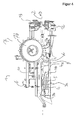
- FIGS. 1 to 6 is shown as a first embodiment of an apparatus 1 for removing parts of plants of at least one elongated, karstabilen, limp growth aid.
- the device is suitable for removing parts of plants from any elongated, tensile, and limp growth aids, such as ropes or wires.
- the device 1 is suitable for use in viticulture to vine shoots, which are cut from the vine, but still adhere as trained on trellis wires growth aid to remove.
- a growth aid 2 indicated as a dashed line.
- the FIG. 5 here represents a lateral view in a sectional view, wherein the sectional plane approximately along the growth aid 2 according to FIG. 4 runs and perpendicular to the plane in the representation according to FIG. 4 lies.
- the device 1 comprises a growth aid guide 3 which has an upwardly open guide channel 3b with an approximately U-shaped cross-section perpendicular to the longitudinal axis of a growth aid 2 lying in the growth aid guide 3.
- the growth aid 2 is guided in particular in the region of a detaching unit 4 of the device 1. This is especially true in the FIGS. 4 and 5 seen.
- the detaching unit 4 comprises a plurality of detachment elements, of which in FIG. 4 two detachment elements 4a and 4b as well as in FIG. 5 two this opposite release elements 4c and 4d are marked.
- the release elements are each formed as cutting blades, which are mounted on a common shaft 5 and by means of a detaching unit motor 6 in rotation according to arrow A in FIG. 5 can be offset.
- the device 1 further comprises a plant guide unit 7, which comprises a lower feed wheel 7a and an upper feed wheel 7b.
- the feed wheels 7a and 7b are driven in opposite directions by means of a second motor 8.
- the direction of rotation is selected such that the side of the feed wheels 7a and 7b facing the stalk 2 are in each case in the direction of passage of the stalk (arrow D in the FIGS. 4 and 5 ) emotional.
- the direction of rotation is additionally in FIG. 2 indicated by arrows.
- the device 1 To use the device 1, this is attached by means of a laterally arranged holder 9 on a (not shown) holding device, which holding device is in turn attached to a (not shown) tractor.
- the holding device By means of the holding device, the device 1 can be varied with respect to the height and with respect to the lateral orientation in the direction of travel right in front of the tractor.
- the trellis wires concerned To use the device in a vineyard with Kordonerziehung either the trellis wires concerned must be removed by hand from the holding masts along a grapevine line or by means of appropriate holding devices, such as open-topped clamping hooks attached to the support poles so that they can be pulled off upwards , On the first and last mast of a row of vines, the trellis wires are permanently attached.
- the device is brought into a position near the first post and the upper Einzugsrad 7 b and a top cover 10 are folded away by pivoting, so that the state according to the FIGS. 4 and 5 results.
- the trellis wire 2 or optionally a plurality of trellis wires is placed from above on the lower feed wheel 7a and introduced into the growth auxiliary guide 3 from above.
- the upper cover 10 and the upper feed wheel 7b are returned to the original position as in FIGS FIGS. 1 . 2 . 3 and 6 shown, brought.
- the growth aids 2 thus run between upper feed wheel 7b and lower feed wheel 7a (see FIG. 2 ) and through the growth aid guide 3 and thus also between the release elements of the release unit 4 (see FIGS. 4 and 5 ).
- the device 1 is moved along above the masts of the grapevine row, so that the trellis wires 2 are pulled upwards out of the holders of the masts, unless they have already been removed from corresponding holders.
- the tractor now moves along the grapevine line, so that the growth aids 2 are passed through the device 1 during this movement.
- the direction of movement of the device is indicated by an arrow C and the relative movement of the growth aids 2 to the device 1 by an arrow D, which relative movement is correspondingly opposite to the direction of movement C of the device 1.
- Plant parts adhering to the trellis wires, in particular vine shoots, are thus guided between the feed wheels 7a and 7b and optionally compressed by compression and fed to the detaching unit 4 (together with the growth aid 2 moving relative to the device 1).
- the trained as a cutting blade, rotating detachment elements 4a, 4b solve the plant parts of the growth aids 2, by shredding, knocking and / or dismemberment.
- the device can thus be in EP 2 486 787 B1 be constructed.
- the lower feed wheel 7a may be formed as a "finger wheel”, as in EP 2 486 787 B1 described.
- the device according to the present invention comprises at least two motor-driven insertion aids.
- insertion aids 12, 13 are formed in the first embodiment as a motor-driven rollers.
- the insertion aids 12, 13 arranged in the direction of passage D of the growth aid 2 in front of the plant guide unit 7.
- the insertion aids 12, 13 are arranged and cooperatively formed with the plant guide unit 3, that when using the device 1, the growth aid 2 between the two insertion aids 12, 13 passes through, so that the insertion aids 12, 13 an insertion of growth aid and plants in the plant guide unit 7 at least horizontally to the right and left limit.
- the insertion area is in FIG. 6 shown as a thick triangle E It is horizontal (see mark H in FIG. 6 ) bounded to the right and left by the insertion aids 12 and 13.
- the growth aid guide 3 comprises a guide roller 3a for the growth aid.
- This guide roller 3a is particularly in the FIGS. 4 . 12 and 13 seen.
- the guide roller 3a is disposed on the common shaft 5 and rotatable relative to this shaft.
- the shaft 5 is rotatable by means of the detaching unit motor 6.
- Guide roller 3a and shaft 5 have a common axis of rotation, in particular, the guide roller 3a is arranged concentrically to the shaft 5.
- the shaft 5 in the region in which the guide roller 3a is arranged can preferably have a shaft adaptation element which has an approximately cylindrical lateral surface, such that the guide roller 3a can be arranged rotatably mounted on the cylindrical surface in a simple manner.
- FIG. 4 is a plan view from above, in which the release elements 4b and 4a are visible to further release elements on one side of the guide roller 3a.
- the guide roller symmetrically as many release elements are arranged, however, in accordance with the plan view FIG. 4 covered by the folded cover and are not visible in it.
- the guide roller 3a since the guide roller 3a is rotatably supported on the shaft 5, the guide roller 3a can rotate counter to the rotational direction A to correspond to the passage direction D of the growth aid 2. This achieves in a simple manner that due to the mechanical contact between growth aid 2 and guide roller 3a, the guide roller 3a rotates at a peripheral speed, which corresponds to the relative speed of the growth aid 2 to the device 1, so that no or only a slight mechanical abrasion between leadership 3a and growth aid 2 is created.
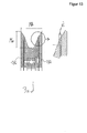
- FIG. 12 shows a plan view from the front of the guide roller 3a. It can be seen here that the guide roller forms an approximately trapezoidal guide region FR.
- the guide roller in the axial direction at the edges of a rising from inside to outside diameter.
- the device 1 further comprises in the axial direction in each case laterally next to the guide roller 3a arranged guide discs 18a and 18b. These are in FIG. 4 due to a reduced representation accordingly only as thin elements visible and better in the Figures 12 and 13 recognizable according to the enlarged view.
- the guide roller 3a is disposed between the guide discs 18a and 18b.
- the guide discs 18a and 18b are rotatably connected to the shaft 5, so that according to the use of the guide discs 18a and 18b according to the direction of rotation A in FIG. 5 rotate and thus have the same rotational speed as the release elements 4a, 4b, 4c and 4d.
- FIG. 13 For better presentation of the embodiment of guide roller 3a and guide discs 18a and 18b is in FIG. 13 an axial section of the marked X 13 in Figure 12 area and additionally in FIG. 13 on the right side a partial enlargement of the area circled on the left side is shown.
- the guide discs 18a and 18b have a larger radius than the guide roller 3a. Furthermore, the guide pulleys overlap the outer edges of the guide roller, see in particular the one with "Ü" in FIG. 13 marked overlap area in the cutout magnification. In the present embodiment, the guide pulleys overlap the outer edges of the guide roller by about 2 mm.
- the axial distance between guide discs 18a and 18b and the axial outer surfaces of the guide rollers 3a is presently about 1.3 mm.
- a guide channel 3b is provided, in particular in the FIGS. 4 and 5 seen.
- the guide channel 3b is formed open at the top, with an approximately U-shaped cross-section.
- the guide channel 3b is arranged in the direction of passage D of the growth aid 2 after the guide roller 3a, so that the growth aid 2 with adhering parts of the plant first enters the sphere of action of the detaching unit 4, so that the plant parts are separated by the separation elements 4a and 4b. Subsequently, the growth aid 2, at which no or only minor residues of plant parts adhere, passes through the guide channel 3b.
- the guide channel 3b thus allows additional stabilization of the growth aid 2 and because of the arranging behind the guide roller 3 ensures that no unfavorable interaction between plant parts and guide channel 3b occurs, which could lead to slipping of the growth aid 2.
- a lubricant opening 19 can be seen in order to add lubricant to a ball bearing between guide roller 3a and shaft 6 can.
- the insertion aids 12 and 13 are driven by means of two Ein 1500 kaunmotoren 14 and 15, which are designed as hydraulic motors.
- the introducers 12, 13 rotate in opposite directions, as in FIG FIG. 3 indicated by corresponding arrows.
- the direction of rotation of the insertion aids 12 and 13 is selected such that the sides of the insertion aids 12 and 13 facing the growth aid 2 rotate in the direction of passage D of the growth aid 2, respectively.
- the device 1 further comprises a control unit, not shown. This controls the rotational speed of the insertion aids 12, 13 and preferably also the feed wheels 7a and 7b.
- the user manually sets the rotational speed by means of the control unit, preferably in such a way that the peripheral speed corresponds approximately to the travel speed of a tractor carrying the device 1.
- the control unit may be connected to a speed measuring system of the tractor and the rotational speed of the insertion aids 12, 13 and preferably also of the feed wheels 7a and 7b is automatically controlled such that the peripheral speed approximately corresponds to the traveling speed of the tractor.
- Each of the growth aid 2 facing side of the insertion aids 12, 13 and the feed wheels 7a, 7b thus has approximately the same speed at which the growth aid 2 passes through the device 1, so that no additional forces due to a relative movement between the scope of Einstocked Anlagenn 12, 13 and feed wheels 7a, 7b and growth aid 2 act on the growth aid.
- the bounding space is thus bounded approximately by the growth aid guide 3 as the apex of a triangle and the insertion aids 12 and 13. Up and down the limiting space is limited by the feed wheels 7a and 7b and in that due to the gravity and the voltage of the growth aid 2, this is pulled down.
- the delimiting space thus has a cross-sectional area perpendicular to the growth aid 2, which has the largest area in the catchment area between the insertion aids 12 and 13 and decreases starting from this to the growth aid guide 3, in particular the guide area FR of the guide roller 3a.
- the opening angle ⁇ between one side of the delimiting space and the growth aid 2 is about 5 ° (the figures are not to scale).
- the insertion aids 12 and 13 can be arranged such that the angle ⁇ , which is determined by the position of the insertion aid 12 to the growth aid 3, different from an opening angle ⁇ , which is determined by the insertion aid 13 and the growth aid 3 significantly.
- the two angles ⁇ and ⁇ are the same.
- the insertion aid 12 has a cylindrical structure, with a regular six-corner (16) as a cross-sectional area.
- comb-like, outwardly projecting transport aids 17 are arranged.
- the transport aids 17 are formed of a flexible material, such as fiber reinforced rubber and have slots 18. By means of screws (not shown), the transport aids 17 can be moved parallel to the surface of the hexagon associated with this transport aid when the screws are loosened.
- FIG. 8b are exemplary directions of movement indicated by arrows in the transport aids 17.
- the transport aids After moving the transport aids 17, the transport aids can in turn be fixed firmly to the basic cylindrical structure by tightening the screws.
- the radius of the circumference of the insertion aid can be changed and thus the effective diameter with which the insertion aids act on the plant parts. This can thus be the "aggressiveness" with which the transport aids on the plant parts, which adhere to the growing habit 2, attack, be varied.
- the insertion aids 12, 13 are connected by means of metallic rods with the basic housing of the device 1. Longholes are provided at the respective connection points, so that adjustment of the angle of insertion aid 12 and insertion aid 13 to the basic housing of the device 1 is possible by loosening fastening screws.
- the distance X according to FIG. 2 between the axes of rotation of the insertion aids 12, 13 and the axis of rotation of the feed wheel 7a may be in the range of 30 to 80 cm. In the present case, the distance is about 40 cm.
- FIGS. 9 to 11 a second embodiment of a device according to the invention is shown.
- the basic structure is similar to the basic structure of the first embodiment, in particular FIG. 9 basically with FIG. 3 .
- Like reference numerals designate like or equivalent elements. To avoid repetition, therefore, only the essential differences are discussed below:
- the second embodiment of a device according to the invention has insertion aids 12 'and 13'. These insertion aids each comprise a conveyor belt 12a 'and 13a'.
- the conveyor belts are driven by hydraulic motors 14 and 15 in opposite directions. Corresponding roles for storage of the conveyor belts are in the FIGS. 9 to 11 not shown for reasons of clarity.
- the operation of the second embodiment is analogous to the above-described operation of the first embodiment.
- the second embodiment has the advantage that, compared with the insertion aids 12 and 13 designed as rollers, an interaction takes place between plant parts and insertion aids over a greater distance: as in FIG. 9 it can be seen, via a conveyor line Y, an action between the conveyor belts 12a 'and 13a' and adhering to the growth aid 2 plant parts done.
- the insertion aids 12 'and 13' are arranged inclined to each other analogous to the insertion aids 12 and 13 and thus form together with a (not shown) auxiliary power guide 3 a confining space as described in the first embodiment.
- the insertion aids 12 'and 13' in plan view from above according to FIG. 9 tapered in the direction of passage D, so that a distance Z1 at a front end of the insertion aids 12 'and 13' is greater than a distance Z2 at a rear end of the insertion aids 12 'and 13'.
- a Vorkomprim ist the plant parts is obtained before the plant parts of the plant management unit 7 with the feed wheels 7a and 7b are supplied for further compression.
- the first compression is approximately perpendicular to the second compression, since the axes of rotation of the rollers of the conveyor belts 12a 'and 13a' are approximately perpendicular to the axes of rotation of the feed wheels 7a and 7b, ie to this at least an angle in the range 45 to 90 ° , preferably 50 ° to 80 °.
- Exemplary is in FIG. 11 such an angle ⁇ between a rotation axis A 7b of the lower Einzugsrads 7b and a rotation axis A 13 'of a roll of the insertion 13' located.
- the operation and design of the growth aid 3 with guide roller 3a and guide channel 3b and the guide discs 18a and 18b is the same in the first and in the second embodiment.
Landscapes
- Life Sciences & Earth Sciences (AREA)
- Biodiversity & Conservation Biology (AREA)
- Ecology (AREA)
- Forests & Forestry (AREA)
- Environmental Sciences (AREA)
- Cultivation Of Plants (AREA)
- Catching Or Destruction (AREA)
Claims (15)
- Dispositif (1) pour supprimer des éléments de plantes d'au moins une aide à la croissance (2) oblongue, stable en traction et molle en flexion, pendant un déplacement du dispositif (1) le long de l'aide à la croissance (2), en particulier pour supprimer des rejets de vigne d'au moins un fil métallique d'espalier,
comprenant- un guide (3) d'aide à la croissance, pour guider l'aide à la croissance (2) pendant le déplacement du dispositif (1) le long de l'aide à la croissance (2),- une unité de détachement (4) et- une unité (7) de guidage de plantes pour comprimer et/ou apporter à l'unité de détachement (4) les éléments de plantes adhérant à l'aide à la croissance (2),
ladite unité de détachement (4) comprenant au moins un élément de détachement qui est disposé à déplacement sur le dispositif (1) de telle sorte qu'en service, par le déplacement de l'élément de détachement, des éléments de plantes peuvent être au moins partiellement détachés de l'aide à la croissance (2),
et ledit élément de détachement étant disposé sur un arbre (5) qui est rotatif au moyen d'un entraînement motorisé du dispositif,
caractérisé en ce que le guide (3) d'aide à la croissance comprend au moins un rouleau de guidage (3a) pour l'aide à la croissance (2), ledit rouleau de guidage (3a) étant disposé à rotation par rapport à l'arbre (5), sachant que le rouleau de guidage (3a) et l'arbre (5) présentent un axe de rotation commun. - Dispositif (1) selon la revendication 1, caractérisé en ce que le rouleau de guidage (3a) est disposé concentriquement par rapport à l'arbre (5).
- Dispositif (1) selon l'une des revendications précédentes, caractérisé en ce que le rouleau de guidage (3a) présente en direction axiale sur les bords un plus grand diamètre que dans une région de guidage intérieure,
en particulier en ce que le rouleau de guidage (3a) présente en direction axiale sur les bords un diamètre respectif augmentant de l'intérieur vers l'extérieur, de préférence un diamètre augmentant de façon monotone, en particulier un diamètre augmentant de façon strictement monotone, d'une manière préférée un diamètre augmentant linéairement. - Dispositif (1) selon la revendication 3, caractérisé en ce que le rouleau de guidage (3a) forme dans une section axiale une région de guidage approximativement trapézoïdale.
- Dispositif (1) selon l'une des revendications précédentes, caractérisé en ce que le rouleau de guidage (3a) présente des arêtes arrondies au moins sur les lignes périphériques extérieures, de préférence en ce que toutes les arêtes du rouleau de guidage (3a) qui sont tournées en utilisation vers l'aide à la croissance (2) sont arrondies.
- Dispositif (1) selon l'une des revendications précédentes, caractérisé en ce que le guide (3) d'aide à la croissance est disposé au moins partiellement dans la zone d'action de l'élément de détachement.
- Dispositif (1) selon l'une des revendications précédentes, caractérisé en ce que le guide (3) d'aide à la croissance présente en plus un canal d'aide à la croissance, de préférence avec une section ouverte vers le haut, en particulier une section approximativement en forme de U.
- Dispositif (1) selon la revendication 7, caractérisé en ce que le canal d'aide à la croissance est disposé après le rouleau de guidage (3a) dans la direction de déplacement de l'aide à la croissance (2).
- Dispositif (1) selon l'une des revendications précédentes, caractérisé en ce que le dispositif (1) comprend au moins deux disques de guidage (18a, 18b), lesdits disques de guidage (18a, 18b) étant disposés en solidarité de rotation sur l'arbre (5).
- Dispositif (1) selon la revendication 9, caractérisé en ce que le rouleau de guidage (3a) est disposé entre les disques de guidage (18a, 18b).
- Dispositif (1) selon la revendication 10, caractérisé en ce que les disques de guidage (18a, 18b) présentent une distance axiale par rapport au rouleau de guidage (3a) dans la plage de 0,1 mm à 20 mm, de préférence de 0,2 mm à 10 mm, d'une manière encore plus préférée de 0,3 mm à 7 mm.
- Dispositif (1) selon l'une des revendications 9 à 11, caractérisé en ce que les disques de guidage (18a, 18b) engagent en recouvrement les bords extérieurs du rouleau de guidage (3a), en particulier engagent en recouvrement en direction axiale une longueur dans la plage de 1 mm à 20 mm, de préférence de 2 mm à 10 mm.
- Dispositif (1) selon l'une des revendications 9 à 12, caractérisé en ce que les disques de guidage extérieurs (18a, 18b) présentent un plus grand diamètre que le rouleau de guidage (3a).
- Dispositif (1) selon l'une des revendications précédentes, caractérisé en ce que l'unité (7) de guidage de plantes est disposée avant l'unité de détachement (4) et avant le guide (3) d'aide à la croissance dans la direction de passage de l'aide à la croissance (2),
et en ce que le dispositif (1) présente au moins deux aides à l'introduction (12, 13, 12', 13') entraînées par moteur, qui sont disposées avant l'unité (7) de guidage de plantes dans la direction de passage de l'aide à la croissance (2),
et les aides à l'introduction sont disposées et sont conçues pour coopérer avec l'unité (7) de guidage de plantes de telle sorte que, lors de l'utilisation du dispositif (1), l'aide à la croissance (2) passe entre les deux aides à l'introduction, de sorte que les aides à l'introduction délimitent au moins horizontalement vers la gauche et la droite la zone d'introduction de l'aide à la croissance (2) et des plantes dans l'unité (7) de guidage de plantes. - Dispositif (1) selon la revendication 14, caractérisé en ce que les aides à l'introduction (12, 13, 12', 13') et le guide (3) d'aide à la croissance sont disposés et sont conçus pour coopérer de telle sorte que les aides à l'introduction et le guide (3) d'aide à la croissance forment un espace de délimitation pour des allures approximativement rectilignes de l'aide à la croissance (2), lequel espace de délimitation ne se chevauche pas avec la zone d'action d'un élément de détachement (4a, 4b) de l'unité de détachement (4).
Applications Claiming Priority (1)
| Application Number | Priority Date | Filing Date | Title |
|---|---|---|---|
| DE201310219651 DE102013219651B3 (de) | 2013-09-27 | 2013-09-27 | Vorrichtung zum Entfernen von Pflanzenteilen von einer Wuchshilfe |
Publications (2)
| Publication Number | Publication Date |
|---|---|
| EP2853149A1 EP2853149A1 (fr) | 2015-04-01 |
| EP2853149B1 true EP2853149B1 (fr) | 2016-01-13 |
Family
ID=51518636
Family Applications (1)
| Application Number | Title | Priority Date | Filing Date |
|---|---|---|---|
| EP14184294.8A Active EP2853149B1 (fr) | 2013-09-27 | 2014-09-10 | Dispositif de tirage de sarments de vignes |
Country Status (2)
| Country | Link |
|---|---|
| EP (1) | EP2853149B1 (fr) |
| DE (1) | DE102013219651B3 (fr) |
Families Citing this family (3)
| Publication number | Priority date | Publication date | Assignee | Title |
|---|---|---|---|---|
| FR2976447B1 (fr) * | 2011-06-20 | 2013-07-12 | Jean-Yves Deze | Machine a tirer automatiquement les sarments de vigne tailles |
| CN105052575B (zh) * | 2015-08-14 | 2017-06-30 | 乌鲁木齐优尼克生物科技有限公司 | 喂料型高效能葡萄枝剪切机 |
| CN105660207B (zh) * | 2016-02-03 | 2018-07-03 | 洛阳农林科学院 | 一种葡萄树树干去死皮装置 |
Family Cites Families (5)
| Publication number | Priority date | Publication date | Assignee | Title |
|---|---|---|---|---|
| NZ583467A (en) * | 2007-10-19 | 2010-10-29 | Honeypot Holdings Ltd | Stripping material from a line, typically grapevines, with line guide, rotating material guide and stripping mechanism |
| NZ587416A (en) * | 2010-08-17 | 2013-06-28 | Honeypot Holdings Ltd | Two part line stripper, with one on either side of the line and with each part having elements of a line guide, a stripping element and a material guide |
| EP2486786A1 (fr) * | 2011-02-14 | 2012-08-15 | ERO-GERÄTEBAU GmbH | Procédé et dispositif destinés à supprimer des éléments de plantes d'un fil de support |
| EP2486787B1 (fr) * | 2011-02-14 | 2013-04-24 | ERO-Gerätebau GmbH | Dispositif destiné à supprimer des éléments de plantes d'une aide à la croissance |
| EP2486789A1 (fr) * | 2011-02-14 | 2012-08-15 | ERO-GERÄTEBAU GmbH | Dispositif destiné à supprimer des éléments de plantes d'une aide à la croissance |
-
2013
- 2013-09-27 DE DE201310219651 patent/DE102013219651B3/de not_active Expired - Fee Related
-
2014
- 2014-09-10 EP EP14184294.8A patent/EP2853149B1/fr active Active
Also Published As
| Publication number | Publication date |
|---|---|
| EP2853149A1 (fr) | 2015-04-01 |
| DE102013219651B3 (de) | 2014-11-20 |
Similar Documents
| Publication | Publication Date | Title |
|---|---|---|
| EP2543452B1 (fr) | Dispositif de pliage pour pièces usinées en forme de tige | |
| EP0740508B1 (fr) | Dispositif pour enrouler une bande de pate | |
| EP0093318A2 (fr) | Machine à découenner | |
| EP3616491A1 (fr) | Machine de récolte de plantes sarclées | |
| EP3007540B1 (fr) | Dispositif à cueillir | |
| DE3028538A1 (de) | Scherenanlage zum schopfen der enden und/oder zum abtrennen von probenstuecken an auf bunde gewickeltem walzband o.dgl. | |
| DE3928196A1 (de) | Vorrichtung zum durchschneiden der isolierung und abstreifen derselben von leiterkerne unterschiedlichen durchmessers enthaltenden leiterstuecken | |
| DE102015112580A1 (de) | Erntegutbergungseinrichtung | |
| EP2853149B1 (fr) | Dispositif de tirage de sarments de vignes | |
| EP2649882B1 (fr) | Dispositif de séparation et de mise en forme de pâte | |
| DE3809496A1 (de) | Ringwickelvorrichtung sowie verfahren zum aufwickeln von wickelgut zu wickelringen | |
| DE60220033T2 (de) | Vorrichtung und verfahren zur auftrennung der gummierung eines förderbands | |
| DE1935414A1 (de) | Vorrichtung zum Entasten von Baeumen | |
| DD213583B5 (de) | Silagegutschneider | |
| EP2823704B1 (fr) | Dispositif et procédé destinés à enlever des parties de plantes | |
| EP2486787B1 (fr) | Dispositif destiné à supprimer des éléments de plantes d'une aide à la croissance | |
| DE3443849A1 (de) | Randabgratvorrichtung fuer stahlblechband | |
| EP2486786A1 (fr) | Procédé et dispositif destinés à supprimer des éléments de plantes d'un fil de support | |
| EP2884833B1 (fr) | Dispositif et procédé pour éliminer des rameaux, notamment des sarments, d'un espalier | |
| EP2486788A1 (fr) | Dispositif destiné à supprimer des éléments de plantes d'une aide à la croissance | |
| EP0814922B1 (fr) | Installation pour le sectionnement de plusieurs longueurs de fils dans un echeveau de fil | |
| EP2457443B1 (fr) | Procédé de torsion mécanique de bandes de pâte | |
| DE19959333B4 (de) | Vorrichtung zum Vereinzeln von Streifen und Verwendungen einer solchen Vorrichtung | |
| EP0894429A1 (fr) | Appareil pour la taille des plantes | |
| EP2486789A1 (fr) | Dispositif destiné à supprimer des éléments de plantes d'une aide à la croissance |
Legal Events
| Date | Code | Title | Description |
|---|---|---|---|
| PUAI | Public reference made under article 153(3) epc to a published international application that has entered the european phase |
Free format text: ORIGINAL CODE: 0009012 |
|
| 17P | Request for examination filed |
Effective date: 20140910 |
|
| AK | Designated contracting states |
Kind code of ref document: A1 Designated state(s): AL AT BE BG CH CY CZ DE DK EE ES FI FR GB GR HR HU IE IS IT LI LT LU LV MC MK MT NL NO PL PT RO RS SE SI SK SM TR |
|
| AX | Request for extension of the european patent |
Extension state: BA ME |
|
| R17P | Request for examination filed (corrected) |
Effective date: 20150325 |
|
| RBV | Designated contracting states (corrected) |
Designated state(s): AL AT BE BG CH CY CZ DE DK EE ES FI FR GB GR HR HU IE IS IT LI LT LU LV MC MK MT NL NO PL PT RO RS SE SI SK SM TR |
|
| RIC1 | Information provided on ipc code assigned before grant |
Ipc: A01G 3/04 20060101AFI20150721BHEP |
|
| GRAP | Despatch of communication of intention to grant a patent |
Free format text: ORIGINAL CODE: EPIDOSNIGR1 |
|
| INTG | Intention to grant announced |
Effective date: 20150907 |
|
| GRAS | Grant fee paid |
Free format text: ORIGINAL CODE: EPIDOSNIGR3 |
|
| GRAA | (expected) grant |
Free format text: ORIGINAL CODE: 0009210 |
|
| AK | Designated contracting states |
Kind code of ref document: B1 Designated state(s): AL AT BE BG CH CY CZ DE DK EE ES FI FR GB GR HR HU IE IS IT LI LT LU LV MC MK MT NL NO PL PT RO RS SE SI SK SM TR |
|
| REG | Reference to a national code |
Ref country code: GB Ref legal event code: FG4D Free format text: NOT ENGLISH |
|
| REG | Reference to a national code |
Ref country code: CH Ref legal event code: EP |
|
| REG | Reference to a national code |
Ref country code: IE Ref legal event code: FG4D Free format text: LANGUAGE OF EP DOCUMENT: GERMAN |
|
| REG | Reference to a national code |
Ref country code: AT Ref legal event code: REF Ref document number: 769857 Country of ref document: AT Kind code of ref document: T Effective date: 20160215 |
|
| REG | Reference to a national code |
Ref country code: DE Ref legal event code: R096 Ref document number: 502014000290 Country of ref document: DE |
|
| REG | Reference to a national code |
Ref country code: LT Ref legal event code: MG4D |
|
| REG | Reference to a national code |
Ref country code: NL Ref legal event code: MP Effective date: 20160113 |
|
| PG25 | Lapsed in a contracting state [announced via postgrant information from national office to epo] |
Ref country code: NL Free format text: LAPSE BECAUSE OF FAILURE TO SUBMIT A TRANSLATION OF THE DESCRIPTION OR TO PAY THE FEE WITHIN THE PRESCRIBED TIME-LIMIT Effective date: 20160113 |
|
| PG25 | Lapsed in a contracting state [announced via postgrant information from national office to epo] |
Ref country code: GR Free format text: LAPSE BECAUSE OF FAILURE TO SUBMIT A TRANSLATION OF THE DESCRIPTION OR TO PAY THE FEE WITHIN THE PRESCRIBED TIME-LIMIT Effective date: 20160414 Ref country code: FI Free format text: LAPSE BECAUSE OF FAILURE TO SUBMIT A TRANSLATION OF THE DESCRIPTION OR TO PAY THE FEE WITHIN THE PRESCRIBED TIME-LIMIT Effective date: 20160113 Ref country code: NO Free format text: LAPSE BECAUSE OF FAILURE TO SUBMIT A TRANSLATION OF THE DESCRIPTION OR TO PAY THE FEE WITHIN THE PRESCRIBED TIME-LIMIT Effective date: 20160413 Ref country code: HR Free format text: LAPSE BECAUSE OF FAILURE TO SUBMIT A TRANSLATION OF THE DESCRIPTION OR TO PAY THE FEE WITHIN THE PRESCRIBED TIME-LIMIT Effective date: 20160113 Ref country code: ES Free format text: LAPSE BECAUSE OF FAILURE TO SUBMIT A TRANSLATION OF THE DESCRIPTION OR TO PAY THE FEE WITHIN THE PRESCRIBED TIME-LIMIT Effective date: 20160113 |
|
| PG25 | Lapsed in a contracting state [announced via postgrant information from national office to epo] |
Ref country code: IS Free format text: LAPSE BECAUSE OF FAILURE TO SUBMIT A TRANSLATION OF THE DESCRIPTION OR TO PAY THE FEE WITHIN THE PRESCRIBED TIME-LIMIT Effective date: 20160513 Ref country code: LV Free format text: LAPSE BECAUSE OF FAILURE TO SUBMIT A TRANSLATION OF THE DESCRIPTION OR TO PAY THE FEE WITHIN THE PRESCRIBED TIME-LIMIT Effective date: 20160113 Ref country code: PT Free format text: LAPSE BECAUSE OF FAILURE TO SUBMIT A TRANSLATION OF THE DESCRIPTION OR TO PAY THE FEE WITHIN THE PRESCRIBED TIME-LIMIT Effective date: 20160513 Ref country code: LT Free format text: LAPSE BECAUSE OF FAILURE TO SUBMIT A TRANSLATION OF THE DESCRIPTION OR TO PAY THE FEE WITHIN THE PRESCRIBED TIME-LIMIT Effective date: 20160113 Ref country code: PL Free format text: LAPSE BECAUSE OF FAILURE TO SUBMIT A TRANSLATION OF THE DESCRIPTION OR TO PAY THE FEE WITHIN THE PRESCRIBED TIME-LIMIT Effective date: 20160113 Ref country code: RS Free format text: LAPSE BECAUSE OF FAILURE TO SUBMIT A TRANSLATION OF THE DESCRIPTION OR TO PAY THE FEE WITHIN THE PRESCRIBED TIME-LIMIT Effective date: 20160113 Ref country code: SE Free format text: LAPSE BECAUSE OF FAILURE TO SUBMIT A TRANSLATION OF THE DESCRIPTION OR TO PAY THE FEE WITHIN THE PRESCRIBED TIME-LIMIT Effective date: 20160113 |
|
| REG | Reference to a national code |
Ref country code: FR Ref legal event code: PLFP Year of fee payment: 3 |
|
| REG | Reference to a national code |
Ref country code: DE Ref legal event code: R097 Ref document number: 502014000290 Country of ref document: DE |
|
| PG25 | Lapsed in a contracting state [announced via postgrant information from national office to epo] |
Ref country code: EE Free format text: LAPSE BECAUSE OF FAILURE TO SUBMIT A TRANSLATION OF THE DESCRIPTION OR TO PAY THE FEE WITHIN THE PRESCRIBED TIME-LIMIT Effective date: 20160113 Ref country code: DK Free format text: LAPSE BECAUSE OF FAILURE TO SUBMIT A TRANSLATION OF THE DESCRIPTION OR TO PAY THE FEE WITHIN THE PRESCRIBED TIME-LIMIT Effective date: 20160113 |
|
| PLBE | No opposition filed within time limit |
Free format text: ORIGINAL CODE: 0009261 |
|
| STAA | Information on the status of an ep patent application or granted ep patent |
Free format text: STATUS: NO OPPOSITION FILED WITHIN TIME LIMIT |
|
| PG25 | Lapsed in a contracting state [announced via postgrant information from national office to epo] |
Ref country code: RO Free format text: LAPSE BECAUSE OF FAILURE TO SUBMIT A TRANSLATION OF THE DESCRIPTION OR TO PAY THE FEE WITHIN THE PRESCRIBED TIME-LIMIT Effective date: 20160113 Ref country code: SM Free format text: LAPSE BECAUSE OF FAILURE TO SUBMIT A TRANSLATION OF THE DESCRIPTION OR TO PAY THE FEE WITHIN THE PRESCRIBED TIME-LIMIT Effective date: 20160113 Ref country code: CZ Free format text: LAPSE BECAUSE OF FAILURE TO SUBMIT A TRANSLATION OF THE DESCRIPTION OR TO PAY THE FEE WITHIN THE PRESCRIBED TIME-LIMIT Effective date: 20160113 Ref country code: SK Free format text: LAPSE BECAUSE OF FAILURE TO SUBMIT A TRANSLATION OF THE DESCRIPTION OR TO PAY THE FEE WITHIN THE PRESCRIBED TIME-LIMIT Effective date: 20160113 |
|
| 26N | No opposition filed |
Effective date: 20161014 |
|
| PG25 | Lapsed in a contracting state [announced via postgrant information from national office to epo] |
Ref country code: BE Free format text: LAPSE BECAUSE OF NON-PAYMENT OF DUE FEES Effective date: 20160930 Ref country code: SI Free format text: LAPSE BECAUSE OF FAILURE TO SUBMIT A TRANSLATION OF THE DESCRIPTION OR TO PAY THE FEE WITHIN THE PRESCRIBED TIME-LIMIT Effective date: 20160113 Ref country code: BG Free format text: LAPSE BECAUSE OF FAILURE TO SUBMIT A TRANSLATION OF THE DESCRIPTION OR TO PAY THE FEE WITHIN THE PRESCRIBED TIME-LIMIT Effective date: 20160413 |
|
| PG25 | Lapsed in a contracting state [announced via postgrant information from national office to epo] |
Ref country code: MC Free format text: LAPSE BECAUSE OF FAILURE TO SUBMIT A TRANSLATION OF THE DESCRIPTION OR TO PAY THE FEE WITHIN THE PRESCRIBED TIME-LIMIT Effective date: 20160113 |
|
| REG | Reference to a national code |
Ref country code: IE Ref legal event code: MM4A |
|
| PG25 | Lapsed in a contracting state [announced via postgrant information from national office to epo] |
Ref country code: IE Free format text: LAPSE BECAUSE OF NON-PAYMENT OF DUE FEES Effective date: 20160910 |
|
| PG25 | Lapsed in a contracting state [announced via postgrant information from national office to epo] |
Ref country code: LU Free format text: LAPSE BECAUSE OF NON-PAYMENT OF DUE FEES Effective date: 20160910 |
|
| REG | Reference to a national code |
Ref country code: FR Ref legal event code: PLFP Year of fee payment: 4 |
|
| REG | Reference to a national code |
Ref country code: BE Ref legal event code: MM Effective date: 20160930 |
|
| REG | Reference to a national code |
Ref country code: CH Ref legal event code: PL |
|
| PG25 | Lapsed in a contracting state [announced via postgrant information from national office to epo] |
Ref country code: HU Free format text: LAPSE BECAUSE OF FAILURE TO SUBMIT A TRANSLATION OF THE DESCRIPTION OR TO PAY THE FEE WITHIN THE PRESCRIBED TIME-LIMIT; INVALID AB INITIO Effective date: 20140910 |
|
| PG25 | Lapsed in a contracting state [announced via postgrant information from national office to epo] |
Ref country code: MT Free format text: LAPSE BECAUSE OF FAILURE TO SUBMIT A TRANSLATION OF THE DESCRIPTION OR TO PAY THE FEE WITHIN THE PRESCRIBED TIME-LIMIT Effective date: 20160113 Ref country code: MK Free format text: LAPSE BECAUSE OF FAILURE TO SUBMIT A TRANSLATION OF THE DESCRIPTION OR TO PAY THE FEE WITHIN THE PRESCRIBED TIME-LIMIT Effective date: 20160113 Ref country code: CY Free format text: LAPSE BECAUSE OF FAILURE TO SUBMIT A TRANSLATION OF THE DESCRIPTION OR TO PAY THE FEE WITHIN THE PRESCRIBED TIME-LIMIT Effective date: 20160113 |
|
| PG25 | Lapsed in a contracting state [announced via postgrant information from national office to epo] |
Ref country code: LI Free format text: LAPSE BECAUSE OF NON-PAYMENT OF DUE FEES Effective date: 20170930 Ref country code: CH Free format text: LAPSE BECAUSE OF NON-PAYMENT OF DUE FEES Effective date: 20170930 |
|
| REG | Reference to a national code |
Ref country code: FR Ref legal event code: PLFP Year of fee payment: 5 |
|
| PG25 | Lapsed in a contracting state [announced via postgrant information from national office to epo] |
Ref country code: AL Free format text: LAPSE BECAUSE OF FAILURE TO SUBMIT A TRANSLATION OF THE DESCRIPTION OR TO PAY THE FEE WITHIN THE PRESCRIBED TIME-LIMIT Effective date: 20160113 Ref country code: TR Free format text: LAPSE BECAUSE OF FAILURE TO SUBMIT A TRANSLATION OF THE DESCRIPTION OR TO PAY THE FEE WITHIN THE PRESCRIBED TIME-LIMIT Effective date: 20160113 |
|
| GBPC | Gb: european patent ceased through non-payment of renewal fee |
Effective date: 20180910 |
|
| PG25 | Lapsed in a contracting state [announced via postgrant information from national office to epo] |
Ref country code: GB Free format text: LAPSE BECAUSE OF NON-PAYMENT OF DUE FEES Effective date: 20180910 |
|
| P01 | Opt-out of the competence of the unified patent court (upc) registered |
Effective date: 20230515 |
|
| PGFP | Annual fee paid to national office [announced via postgrant information from national office to epo] |
Ref country code: AT Payment date: 20230915 Year of fee payment: 10 |
|
| PGFP | Annual fee paid to national office [announced via postgrant information from national office to epo] |
Ref country code: IT Payment date: 20230929 Year of fee payment: 10 |
|
| PGFP | Annual fee paid to national office [announced via postgrant information from national office to epo] |
Ref country code: DE Payment date: 20240725 Year of fee payment: 11 |
|
| PGFP | Annual fee paid to national office [announced via postgrant information from national office to epo] |
Ref country code: FR Payment date: 20240924 Year of fee payment: 11 |
|
| REG | Reference to a national code |
Ref country code: AT Ref legal event code: MM01 Ref document number: 769857 Country of ref document: AT Kind code of ref document: T Effective date: 20240910 |
|
| PG25 | Lapsed in a contracting state [announced via postgrant information from national office to epo] |
Ref country code: IT Free format text: LAPSE BECAUSE OF NON-PAYMENT OF DUE FEES Effective date: 20240910 |
|
| PG25 | Lapsed in a contracting state [announced via postgrant information from national office to epo] |
Ref country code: AT Free format text: LAPSE BECAUSE OF NON-PAYMENT OF DUE FEES Effective date: 20240910 |