EP2853286B1 - Vorrichtung zur Behandlung von Periimplantitis - Google Patents
Vorrichtung zur Behandlung von Periimplantitis Download PDFInfo
- Publication number
- EP2853286B1 EP2853286B1 EP13425128.9A EP13425128A EP2853286B1 EP 2853286 B1 EP2853286 B1 EP 2853286B1 EP 13425128 A EP13425128 A EP 13425128A EP 2853286 B1 EP2853286 B1 EP 2853286B1
- Authority
- EP
- European Patent Office
- Prior art keywords
- electrical
- implant
- damaged tissue
- detector
- power
- Prior art date
- Legal status (The legal status is an assumption and is not a legal conclusion. Google has not performed a legal analysis and makes no representation as to the accuracy of the status listed.)
- Active
Links
- 238000011282 treatment Methods 0.000 title claims description 9
- 239000007943 implant Substances 0.000 claims description 71
- 238000005259 measurement Methods 0.000 claims description 11
- 230000007935 neutral effect Effects 0.000 claims description 9
- 239000004053 dental implant Substances 0.000 claims description 8
- 239000002184 metal Substances 0.000 claims description 2
- 210000001519 tissue Anatomy 0.000 description 42
- 238000001356 surgical procedure Methods 0.000 description 5
- 210000000988 bone and bone Anatomy 0.000 description 4
- 241000894006 Bacteria Species 0.000 description 2
- 230000005540 biological transmission Effects 0.000 description 2
- 230000004054 inflammatory process Effects 0.000 description 2
- 238000000034 method Methods 0.000 description 2
- 206010061218 Inflammation Diseases 0.000 description 1
- 238000009825 accumulation Methods 0.000 description 1
- 210000005178 buccal mucosa Anatomy 0.000 description 1
- 238000010586 diagram Methods 0.000 description 1
- 238000001827 electrotherapy Methods 0.000 description 1
- 238000002474 experimental method Methods 0.000 description 1
- 230000035876 healing Effects 0.000 description 1
- 239000000463 material Substances 0.000 description 1
- 239000012528 membrane Substances 0.000 description 1
- 210000004877 mucosa Anatomy 0.000 description 1
- 230000000144 pharmacologic effect Effects 0.000 description 1
- 230000000750 progressive effect Effects 0.000 description 1
- 230000001720 vestibular Effects 0.000 description 1
Images


Classifications
-
- A—HUMAN NECESSITIES
- A61—MEDICAL OR VETERINARY SCIENCE; HYGIENE
- A61N—ELECTROTHERAPY; MAGNETOTHERAPY; RADIATION THERAPY; ULTRASOUND THERAPY
- A61N1/00—Electrotherapy; Circuits therefor
- A61N1/02—Details
- A61N1/04—Electrodes
- A61N1/06—Electrodes for high-frequency therapy
-
- A—HUMAN NECESSITIES
- A61—MEDICAL OR VETERINARY SCIENCE; HYGIENE
- A61N—ELECTROTHERAPY; MAGNETOTHERAPY; RADIATION THERAPY; ULTRASOUND THERAPY
- A61N1/00—Electrotherapy; Circuits therefor
- A61N1/02—Details
- A61N1/04—Electrodes
- A61N1/05—Electrodes for implantation or insertion into the body, e.g. heart electrode
- A61N1/0526—Head electrodes
- A61N1/0548—Oral electrodes
-
- A—HUMAN NECESSITIES
- A61—MEDICAL OR VETERINARY SCIENCE; HYGIENE
- A61N—ELECTROTHERAPY; MAGNETOTHERAPY; RADIATION THERAPY; ULTRASOUND THERAPY
- A61N1/00—Electrotherapy; Circuits therefor
- A61N1/18—Applying electric currents by contact electrodes
- A61N1/32—Applying electric currents by contact electrodes alternating or intermittent currents
Definitions
- the present patent application for industrial invention relates to a device for treatment of perimplantitis.
- Implant surgery is getting more and more used to replace dental elements that are missing. Therefore, osteointegrated dental implants are used by a growing percentage of individuals.
- Perimplantitis is caused by the accumulation of bacteria on the surface of osteointegrated implants, which causes an inflammation state known as perimplantitis.
- This inflammatory process determines a progressive loss of the bone tissue that supports the osteointegrated implant until the implant is lost.
- Treatments that are currently used to treat perimplantitis can be of pharmacological (non-invasive) type or of surgery (invasive) type.
- a first type of surgical treatment for perimplantitis consists in cutting the inflamed gum in correspondence of the osteointegrated implant, in such manner to remove the infected portion of the gum and graft heterologous bone material.
- a second type of surgical treatment for perimplantitis provides for laser using; the objective is to eliminate the bacteria that cause perimplantitis and remove the damaged perimplantar tissue.
- US4,175,565 discloses an electro-conductive dental implant having a cathode permanently imbedded in the jawbone, and an anode connected to a skin of the patent and to a source. A continuous current of 200 microamperes is applied intermittently for short periods, in order to increase the rate of the normal healing process.
- WO01/51122 discloses an electrotherapy apparatus for providing two oscillating or pulsing electric alternating currents of frequencies which differ from each other by 1-250 Hz, at frequency of 1 KHz.
- the purpose of the present invention is to remedy the drawbacks of the aforementioned surgical techniques, by disclosing a device for treatment of perimplantitis that is efficacious, easy to use and able to treat perimplantitis in a not very invasive way for the patient.
- perimplantitis can be treated by delivering high-frequency alternating current on the damaged tissue, using the dental implant as current dissipator terminal.
- the inventor has discovered that the best results are obtained if a constant power dissipation of about 200W is maintained on the damaged tissue.
- the inventor has realized that the variation of power dissipated on the damaged tissue strictly depends on the variation of electrical resistance of the damaged tissue.
- the inventor has developed a device for treatment of perimplantitis able to detect the electrical resistance of the damaged tissue and, according to the resistance value detected, modulate the characteristics of an electrical pulse train at alternating current and high-frequency delivered through the implant to the damaged tissue.
- the device can optionally detect the extension and electrical affinity of the damaged tissue and accordingly modulate the characteristics of the high-frequency alternating current electrical pulse train delivered through the implant to the damaged tissue.
- a dental implant is illustrated, which is implanted in a bone tissue (O) covered by the gum (GE).
- Fig. 1 shows the portions of the gum (GE) forming the buccal mucosa and vestibular mucosa.
- a damaged tissue (T) affected by perimplantitis is illustrated with dots in the portion of bone (O) and gum (GE) in the proximity of the dental implant (IM).
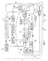
- the device (1) of the invention comprises:
- the pulse train (I) can be administered to the damaged tissue (T) through the surface of the implant (IM); whereas, by means of the second closed electrical circuit (C'), the resistance detector (5) can detect the electrical resistance of the damaged tissue (T) in the proximity of the implant (IM).
- the neutral electrode (E2) is positioned on the cheek (G) in correspondence of the damaged tissue (T), otherwise the measurement of the electrical resistance may be unreliable.
- the electrical power supply (3) advantageously comprises a low-power current outlet (31) that powers the resistance detector (5) and a high-power current outlet (32) that powers the pulse generator (2).
- the resistance detector (5) receives a low voltage electrical current to detect the electrical resistance of the damaged tissue (T).
- the pulse generator (2) receives a high-voltage alternating current to generate the pulse train (I) to be sent to the implant (IM).
- the pulse train (I) is characterized by:
- the main electrode (E1) is connected to a handpiece (M) (see Fig. 4 ) adapted to be held by the operator.
- the main electrode (E1) has a tip with 2 mm diameter in order to have a stable contact with the implant (IM) (see Fig. 1 ), carefully avoiding any direct contact of the electrode (E1) with the damaged tissue (T).
- the implant (IM) works as an antenna that dissipates the energy associated with the passage of current in equipotential mode on the entire contact surface between the implant (IM) and the damaged tissue (T).
- the device (1) also comprises a safety relay (6) and a switch (7) disposed between generator (2) and main electrode (E1).
- the safety relay (6) is normally closed and opens when the detected resistance is such to develop a dissipated power higher than a predefined threshold value.
- the switch (7) is normally open and is connected to a button (P) provided on the handpiece (M). When closing, the switch (7) activates the measurement of the resistance detector (5) and the transmission of the high-power pulse (I) by the pulse generator (2).
- the power supply (3) transmits a low-voltage electrical signal (C0) to the main electrode (E1) disposed in contact with the implant (IM).
- the low-voltage electrical signal (C0) passes through the resistance detector (5). Consequently, the resistance detector (5) detects, instant by instant, the electrical resistance of the damaged tissue (T) according to the electrical current that passes through the closed electrical circuit (C) of the device (1).
- the electrical resistance value of the damaged tissue (T) is measured in K ⁇ .
- the device (1) comprises a display (D) connected to the resistance detector (5).
- the display (D) shows the electrical resistance value detected by the resistance detector (5) instant by instant.
- the resistance detector (5) transmits a control signal (C1) to the power controller (4) according to the electrical resistance detected.
- the power controller (4) receives the control signal (C1) of the resistance detector (5) and transmits a control signal (C2) to the generator (2) according to the electrical resistance detected by the resistance detector (5).
- the power controller (4) can also be actuated manually with a knob (M3) (see Fig. 4 ).
- the pulse generator (2) receives the control signal (C2) sent by the power controller (4) and generates an electrical pulse train (I) with power (Ip) proportional to the electrical resistance value detected by the electrical resistance detector (5).
- the electrical pulse train (I) generated by the generator (2) is transmitted to the main electrode (E1) after manually actuating the button (P) provided on the handpiece (M) of the main electrode (E1).
- the button (P) is electrically connected to the switch (7) and controls said switch (7). When the button (P) is pressed by the operator, the switch (7) is closed, allowing for the electrical pulse train (I) to pass from the generator (2) to the main electrode (E1).
- the electrical power developed by the electrical pulse train (I) in the damaged tissue (T) must be maintained at a constant value of about 200 Watt. In fact, if the power dissipated in the damaged tissue (T) is higher than 200 Watt, the damaged tissue (T) will be damaged, whereas if the power dissipated in the damaged tissue is lower than 200 Watt, the electrical pulse train (I) delivered by the main electrode (E1) will be ineffective for the treatment of the damaged tissue (T).
- the power dissipated by the damaged tissue (T) depends on the electrical resistance value of the damaged tissue. Therefore, the electrical power (Ip) of the pulse train (I) generated by the pulse generator varies according to the electrical resistance value detected by the resistance detector (5).
- the power (Ip) of the pulse train (I) generated by the pulse generator (2) and delivered by the main electrode (E1) on the damaged tissue (T) varies case by case according to the electrical resistance value of the damaged tissue (T) in order to maintain the value of the electrical power dissipated on the damaged tissue (T) constant.
- the relay (6) is normally closed and opens when it detects a power value (Ip) of the pulse train (I) generated by the generator (2) higher than 200 Watt. Consequently, said relay (6) prevents the passage of the electrical pulse train (I) from the generator (2) to the main electrode (E1), in contact with the implant (IM), when the power (Ip) of said electrical pulse train (I) is higher than the predefined value.
- the device (1) of the invention comprises:
- the dimensional detector (8) transmits a control signal (C3) to the duration controller (9) in such manner that the duration (Id) of the electrical pulse train (I) generated by the generator (2) is controlled according to the extension of the damaged tissue (T).
- the dimensional detector (8) receives data from one or more implant stability measurement devices (80) connected to the dimensional detector (8). According to the data received by the implant stability measurement devices (80), the dimensional detector (8) calculates an implant relative stability (IRS) value.
- ILS implant relative stability
- the duration (Id) of the electrical pulse train (I) generated by the generator (2) is controlled by the duration controller (9) according to the implant relative stability (IRS) values in inverse relation; the higher the IRS values, the lower the duration (Id) of the pulse train delivered.
- the duration (Id) of the pulse train can vary from 80 to 160 ms.
- the implant stability measurement device (80) comprises an OSSTELL ® implant stability meter.
- the OSSTELL ® implant stability meter comprises a metal connector (81) adapted to be fixed to the osteointegrated implant (IP) to detect implant stability.
- the OSSTELL ® implant stability meter is a device of known type used to measure the stability of an osteointegrated implant by means of a Resonance Frequency Analysis (RFA) technique.
- the RFA technique provides for fixing the connector (81) on the osteointegrated implant by means of a screw.
- the connector (81) is provided with upper part comprising a magnet that is stimulated by magnetic pulses emitted by an electronic device.
- the connector (81) mounted on the osteointegrated implant has two main resonance frequencies and vibrates in two perpendicular directions, of which a first direction in which the implant is more stable and a second direction in which the implant is less stable.
- the OSSTELL ® implant stability meter provides Implant Stability Quotient (ISQ) values comprised from 1 to 100.
- ISQ Implant Stability Quotient
- the OSSTELL ® implant stability meters sends the ISQ values to the dimensional detector (8) that converts them into implant relative stability values (IRS) sent to the duration controller (9) to control the duration (Id) of the electrical pulse train (I) generated by the generator (2).
- IRS implant relative stability values
- the device (1) also comprises:
- the electrical affinity detector (F) sends a control signal (C4) to the frequency controller (F1) according to the electrical affinity value measured. Therefore the frequency controller (F1) controls the frequency (If) of the electrical pulse train (I) in a frequency range from 200 to 700 khz.
- the electrical affinity detector (F) comprises a direct current voltmeter (100) connected to the electrode (E1) disposed in contact with the implant (IM) and to the neutral electrode (E2) disposed on the cheek.
- the measurement of the voltmeter (100) is made in mvolts and is read on the voltmeter display. Such a measurement is made by closing the switch (7) actuated by the button (P) on the handpiece (M).
- the frequency (If) of the electrical pulse train (I) generated by the generator (2) is controlled by the frequency controller (F1) according to the electrical affinity values measured by the voltmeter (100).
- the switch (7) When closing, the switch (7) activates the measurements of the resistance, dimensional and electrical affinity detectors (5, 8, F) in a sequence and the transmission of the high-power pulse (I) towards the implant (IM).
- the device (1) of the invention optionally comprises three knobs (M1, M2, M3) used to manually control the frequency (If), duration (Id) and power (Ip) of the electrical pulse train (I) generated by the generator (2).
Landscapes
- Health & Medical Sciences (AREA)
- Engineering & Computer Science (AREA)
- Biomedical Technology (AREA)
- Nuclear Medicine, Radiotherapy & Molecular Imaging (AREA)
- Radiology & Medical Imaging (AREA)
- Life Sciences & Earth Sciences (AREA)
- Animal Behavior & Ethology (AREA)
- General Health & Medical Sciences (AREA)
- Public Health (AREA)
- Veterinary Medicine (AREA)
- Cardiology (AREA)
- Heart & Thoracic Surgery (AREA)
- Electrotherapy Devices (AREA)
Claims (9)
- Vorrichtung (1) für die Behandlung von Periimplantitis, umfassend:- einen Impulserzeuger (2), der dazu geeignet ist, eine Folge von hochfrequenten Elektroimpulsen (i) zu erzeugen;- ein elektrisches Netzteil (3), das elektrisch am Impulserzeuger (2) angeschlossen ist;- eine Hauptelektrode (E1), die am Impulserzeuger (2) angeschlossen und dazu bestimmt ist, im Kontakt mit einem enossalen Zahnimplantat (IM), das von Periimplantitis an einem erkrankten Gewebe (T) betroffen ist, positioniert zu werden;- eine Neutralelektrode (E2), die an dem elektrischen Netzteil (3) angeschlossen und dazu bestimmt ist, in engem Kontakt mit einer Wange (G) des Patienten im Bereich des an Periimplantitis erkrankten Gewebes (T) derart zu positioniert zu werden, dass ein geschlossener Stromkreis (C) gebildet wird, um die Impulsfolge in das erkrankte Gewebe (T) einzuleiten,
dadurch gekennzeichnet, dass die Vorrichtung ferner Folgendes umfasst:- einen Widerstandsmesser (5), der zwischen dem elektrischen Netzteil (3) und der Hauptelektrode (E1) derart angeordnet wird, dass ein zweiter geschlossener Stromkreis (C') gebildet wird, um den Elektrowiderstand des erkrankten Gewebes (T) zu messen,- einen Leistungsregler (4), der zwischen dem Widerstandsmesser (5) und dem Impulserzeuger (2) angeordnet wird, um die Leistung (Ip) der Impulsfolge (i) entsprechend dem Elektrowiderstand des erkrankten Gewebes zu regeln;wobei der Impulserzeuger (2) vorgesehen ist, um eine Impulsfolge (I) mit folgenden Merkmalen zu erzeugen:- eine Frequenz (If), die im Bereich zwischen 200 - 700 KHz liegt;- eine Dauer (Id), die im Bereich zwischen 80 und 160 ms liegt; und- eine Leistung (Ip), die zwischen 40% und 100% eines zuvor festgelegten Höchstleistungswerts PMAX variieren kann und in der Lage ist, eine dissipierte Leistung von 200 WATT in dem erkrankten Gewebe zu erzeugen. - Vorrichtung (1) nach Anspruch 1, wobei das elektrische Netzteil (3) einen Ausgang für Niederfrequenzstrom (31) umfasst, der den Widerstandsmesser (5) versorgt, und einen Ausgang für Hochfrequenzstrom (32), der den Impulserzeuger (2) versorgt.
- Vorrichtung (1) nach einem beliebigen der vorstehenden Ansprüche, umfassend ferner ein Sicherheitsrelais (6) und einen Schalter (7), welche zwischen dem Impulserzeuger (2) und der Hauptelektrode (E1) angeordnet sind, wobei das Sicherheitsrelais (6) normalerweise geschlossen ist und nur dann geöffnet wird, wenn eine dissipierte elektrische Leistung gemessen wird, die einen voreingestellten Schwellenwert überschreitet, und der Schalter (7) normalerweise geöffnet und mit einer Taste (P) verbunden ist, die an einem Handstück (M) angeordnet ist, das mit der Hauptelektrode (E1) verbunden ist.
- Vorrichtung (1) nach einem beliebigen der vorstehenden Ansprüche, umfassend ferner ein Display (D), das mit dem Widerstandsmesser (5) verbunden ist, um den gemessenen Widerstand anzuzeigen.
- Vorrichtung (1) nach einem beliebigen der vorstehenden Ansprüche, umfassend ferner:- einen Größenmesser (8), der die Ausdehnung des erkrankten Gewebes (T) berechnet; und- einen Dauerregler (9), der elektrisch mit dem Größenmesser (8) verbunden und dazu geeignet ist, die Dauer (Id) der Elektroimpulsfolge (I), die vom Impulserzeuger (2) erzeugt wird, entsprechend der Ausdehnung des erkrankten Gewebes zu regulieren.
- Vorrichtung (1) nach Anspruch 5, umfassend ferner mindestens einen Implantatstabilitätsmesser (80), der mit dem Größenmesser (8) verbunden ist, um die Werte der relativen Implatatstabilität (IRS) zu messen, wobei der Größenmesser (8) an den Dauerregler (9) Signale (C3) sendet, die auf die relative Implatatstabilität (IRS) hinweisen, die vom Stabilitätsmesser (80) gemessen wird.
- Vorrichtung (1) nach Anspruch 6, wobei der Implantatstabilitätsmesser (80) ein OSSTELL umfasst, das mit einem Metallverbinder (81) versehen und dazu bestimmt ist, am Implantat (IP) befestigt zu werden, um den Implantatstabilitätsquotienten (ISQ) zu ermitteln.
- Vorrichtung (1) nach einem beliebigen der vorstehenden Ansprüche, umfassend ferner:- einen Elektroaffinitätsmesser (F), der das transmuköse Elektropotential des periimplantaren Gewebes (T) misst, und- einen Frequenzregler (F1), der elektrisch mit dem Elektroaffinitätsmesser (F) verbunden und dazu geeignet ist, die Frequenz (If) der Elektroimpulsfolge (I), die vom Impulserzeuger (2) erzeugt wird, entsprechend dem vom Elektroaffinitätsmesser (F) ermittelten Elektroaffinitätswert zu variieren.
- Vorrichtung (1) nach Anspruch 8, wobei der Elektroaffinitätsmesser (F) ein Voltmeter (100) umfasst, die Hauptelektrode (E1) im Kontakt mit dem Implantat (IM) angeordnet ist und die Neutralelektrode (E2) sich im Kontakt mit der Wange (G) befindet.
Priority Applications (1)
| Application Number | Priority Date | Filing Date | Title |
|---|---|---|---|
| EP13425128.9A EP2853286B1 (de) | 2013-09-25 | 2013-09-25 | Vorrichtung zur Behandlung von Periimplantitis |
Applications Claiming Priority (1)
| Application Number | Priority Date | Filing Date | Title |
|---|---|---|---|
| EP13425128.9A EP2853286B1 (de) | 2013-09-25 | 2013-09-25 | Vorrichtung zur Behandlung von Periimplantitis |
Publications (2)
| Publication Number | Publication Date |
|---|---|
| EP2853286A1 EP2853286A1 (de) | 2015-04-01 |
| EP2853286B1 true EP2853286B1 (de) | 2015-11-18 |
Family
ID=49679461
Family Applications (1)
| Application Number | Title | Priority Date | Filing Date |
|---|---|---|---|
| EP13425128.9A Active EP2853286B1 (de) | 2013-09-25 | 2013-09-25 | Vorrichtung zur Behandlung von Periimplantitis |
Country Status (1)
| Country | Link |
|---|---|
| EP (1) | EP2853286B1 (de) |
Cited By (1)
| Publication number | Priority date | Publication date | Assignee | Title |
|---|---|---|---|---|
| DE102023100442A1 (de) | 2023-01-10 | 2024-07-11 | Hubertus Platt | Verfahren und Vorrichtung zur vorbeugenden Behandlung von Periimplantitis |
Families Citing this family (1)
| Publication number | Priority date | Publication date | Assignee | Title |
|---|---|---|---|---|
| CN114653567B (zh) * | 2022-01-18 | 2025-02-28 | 江苏岱洛医疗科技有限公司 | 一种脉冲磁场振动装置 |
Family Cites Families (4)
| Publication number | Priority date | Publication date | Assignee | Title |
|---|---|---|---|---|
| US4175565A (en) * | 1977-06-22 | 1979-11-27 | Oratronics, Inc. | Method and apparatus for stimulating osteogenic activity in bone structure adjacent a dental implant |
| US5030236A (en) * | 1989-06-19 | 1991-07-09 | Intermedics Orthopedics, Inc. | Apparatus for enhancing biointegration of bony and endoprosthesis structures |
| US5496256A (en) * | 1994-06-09 | 1996-03-05 | Sonex International Corporation | Ultrasonic bone healing device for dental application |
| EP1246665B1 (de) * | 2000-01-07 | 2005-08-24 | Biowave Corporation | Vorrichtung zur elektrotherapie |
-
2013
- 2013-09-25 EP EP13425128.9A patent/EP2853286B1/de active Active
Cited By (1)
| Publication number | Priority date | Publication date | Assignee | Title |
|---|---|---|---|---|
| DE102023100442A1 (de) | 2023-01-10 | 2024-07-11 | Hubertus Platt | Verfahren und Vorrichtung zur vorbeugenden Behandlung von Periimplantitis |
Also Published As
| Publication number | Publication date |
|---|---|
| EP2853286A1 (de) | 2015-04-01 |
Similar Documents
| Publication | Publication Date | Title |
|---|---|---|
| US11523864B2 (en) | Methods and systems related to an electrosurgical controller | |
| JP4041165B2 (ja) | 高周波電流を使用して歯を失活させる装置 | |
| WO2019134008A3 (en) | Radio frequency energy device for delivering combined electrical signals | |
| ATE292491T1 (de) | System zur bestimmung des gewebekontaktes einer implantierbaren vorrichtung | |
| CA2538199A1 (en) | Systems and methods for intra-operative stimulation | |
| ATE507786T1 (de) | Rückkopplungssystem für rf-ablation mittels virtueller elektrode und schutzkühlung | |
| EP2853286B1 (de) | Vorrichtung zur Behandlung von Periimplantitis | |
| US4550728A (en) | Epilator | |
| TWI423790B (zh) | 可調式電極植入系統及其可調式電極植入裝置 | |
| CN1929789B (zh) | 监控器具穿刺进入解剖结构的装置 | |
| US6443732B2 (en) | Apparatus and method for treating infected tooth using ionophoresis | |
| JP2016517760A (ja) | 人体および動物からの組織塊切除用電気外科治療器具 | |
| WO2014020584A1 (en) | System and method for treating tissue | |
| KR102603577B1 (ko) | 전극과 생체간 접촉 상태에 따른 자극 세기 조절이 가능한 의료용 전기 자극기 | |
| JP3568531B2 (ja) | パルス化された磁気誘導のための方法および装置 | |
| CA2754174C (en) | A system for implanting, activating, and operating an implantable battery | |
| KR20210035595A (ko) | 마우스피스형 미세전류 자극기 | |
| EP3081261A1 (de) | Intraorales element zur anwendung von energieversorgungsbehandlungen in kieferknochen, zahnfleisch oder anderem gewebe im mund | |
| KR20200094911A (ko) | 전압 값 차이 기반 제어에 의한 고주파 치료장치 및 치료방법 | |
| GB2434539A (en) | Implanted pain relieving nerve stimulator with insertion wire acting as temporary power cable | |
| Robinson | for Electrotherapy | |
| JPH078565A (ja) | 骨疾患治療用磁気刺激装置 | |
| JP2023160756A (ja) | 中性電極の電極タイプを決定するための電気外科システムおよび方法 | |
| Vernon | Use of electricity to suppress tinnitus | |
| JP2004321273A (ja) | 治療装置および治療装置に用いられる処置具 |
Legal Events
| Date | Code | Title | Description |
|---|---|---|---|
| PUAI | Public reference made under article 153(3) epc to a published international application that has entered the european phase |
Free format text: ORIGINAL CODE: 0009012 |
|
| 17P | Request for examination filed |
Effective date: 20131122 |
|
| AK | Designated contracting states |
Kind code of ref document: A1 Designated state(s): AL AT BE BG CH CY CZ DE DK EE ES FI FR GB GR HR HU IE IS IT LI LT LU LV MC MK MT NL NO PL PT RO RS SE SI SK SM TR |
|
| AX | Request for extension of the european patent |
Extension state: BA ME |
|
| GRAP | Despatch of communication of intention to grant a patent |
Free format text: ORIGINAL CODE: EPIDOSNIGR1 |
|
| INTG | Intention to grant announced |
Effective date: 20150528 |
|
| GRAS | Grant fee paid |
Free format text: ORIGINAL CODE: EPIDOSNIGR3 |
|
| GRAA | (expected) grant |
Free format text: ORIGINAL CODE: 0009210 |
|
| AK | Designated contracting states |
Kind code of ref document: B1 Designated state(s): AL AT BE BG CH CY CZ DE DK EE ES FI FR GB GR HR HU IE IS IT LI LT LU LV MC MK MT NL NO PL PT RO RS SE SI SK SM TR |
|
| AX | Request for extension of the european patent |
Extension state: BA ME |
|
| REG | Reference to a national code |
Ref country code: GB Ref legal event code: FG4D |
|
| REG | Reference to a national code |
Ref country code: CH Ref legal event code: EP |
|
| REG | Reference to a national code |
Ref country code: AT Ref legal event code: REF Ref document number: 761202 Country of ref document: AT Kind code of ref document: T Effective date: 20151215 |
|
| REG | Reference to a national code |
Ref country code: IE Ref legal event code: FG4D |
|
| REG | Reference to a national code |
Ref country code: DE Ref legal event code: R096 Ref document number: 602013003887 Country of ref document: DE |
|
| REG | Reference to a national code |
Ref country code: NL Ref legal event code: MP Effective date: 20160218 |
|
| REG | Reference to a national code |
Ref country code: LT Ref legal event code: MG4D |
|
| REG | Reference to a national code |
Ref country code: AT Ref legal event code: MK05 Ref document number: 761202 Country of ref document: AT Kind code of ref document: T Effective date: 20151118 |
|
| PG25 | Lapsed in a contracting state [announced via postgrant information from national office to epo] |
Ref country code: NO Free format text: LAPSE BECAUSE OF FAILURE TO SUBMIT A TRANSLATION OF THE DESCRIPTION OR TO PAY THE FEE WITHIN THE PRESCRIBED TIME-LIMIT Effective date: 20160218 Ref country code: ES Free format text: LAPSE BECAUSE OF FAILURE TO SUBMIT A TRANSLATION OF THE DESCRIPTION OR TO PAY THE FEE WITHIN THE PRESCRIBED TIME-LIMIT Effective date: 20151118 Ref country code: LT Free format text: LAPSE BECAUSE OF FAILURE TO SUBMIT A TRANSLATION OF THE DESCRIPTION OR TO PAY THE FEE WITHIN THE PRESCRIBED TIME-LIMIT Effective date: 20151118 Ref country code: HR Free format text: LAPSE BECAUSE OF FAILURE TO SUBMIT A TRANSLATION OF THE DESCRIPTION OR TO PAY THE FEE WITHIN THE PRESCRIBED TIME-LIMIT Effective date: 20151118 Ref country code: NL Free format text: LAPSE BECAUSE OF FAILURE TO SUBMIT A TRANSLATION OF THE DESCRIPTION OR TO PAY THE FEE WITHIN THE PRESCRIBED TIME-LIMIT Effective date: 20151118 Ref country code: IT Free format text: LAPSE BECAUSE OF FAILURE TO SUBMIT A TRANSLATION OF THE DESCRIPTION OR TO PAY THE FEE WITHIN THE PRESCRIBED TIME-LIMIT Effective date: 20151118 Ref country code: IS Free format text: LAPSE BECAUSE OF FAILURE TO SUBMIT A TRANSLATION OF THE DESCRIPTION OR TO PAY THE FEE WITHIN THE PRESCRIBED TIME-LIMIT Effective date: 20160318 |
|
| PG25 | Lapsed in a contracting state [announced via postgrant information from national office to epo] |
Ref country code: PL Free format text: LAPSE BECAUSE OF FAILURE TO SUBMIT A TRANSLATION OF THE DESCRIPTION OR TO PAY THE FEE WITHIN THE PRESCRIBED TIME-LIMIT Effective date: 20151118 Ref country code: SE Free format text: LAPSE BECAUSE OF FAILURE TO SUBMIT A TRANSLATION OF THE DESCRIPTION OR TO PAY THE FEE WITHIN THE PRESCRIBED TIME-LIMIT Effective date: 20151118 Ref country code: RS Free format text: LAPSE BECAUSE OF FAILURE TO SUBMIT A TRANSLATION OF THE DESCRIPTION OR TO PAY THE FEE WITHIN THE PRESCRIBED TIME-LIMIT Effective date: 20151118 Ref country code: GR Free format text: LAPSE BECAUSE OF FAILURE TO SUBMIT A TRANSLATION OF THE DESCRIPTION OR TO PAY THE FEE WITHIN THE PRESCRIBED TIME-LIMIT Effective date: 20160219 Ref country code: PT Free format text: LAPSE BECAUSE OF FAILURE TO SUBMIT A TRANSLATION OF THE DESCRIPTION OR TO PAY THE FEE WITHIN THE PRESCRIBED TIME-LIMIT Effective date: 20160318 Ref country code: FI Free format text: LAPSE BECAUSE OF FAILURE TO SUBMIT A TRANSLATION OF THE DESCRIPTION OR TO PAY THE FEE WITHIN THE PRESCRIBED TIME-LIMIT Effective date: 20151118 Ref country code: AT Free format text: LAPSE BECAUSE OF FAILURE TO SUBMIT A TRANSLATION OF THE DESCRIPTION OR TO PAY THE FEE WITHIN THE PRESCRIBED TIME-LIMIT Effective date: 20151118 Ref country code: LV Free format text: LAPSE BECAUSE OF FAILURE TO SUBMIT A TRANSLATION OF THE DESCRIPTION OR TO PAY THE FEE WITHIN THE PRESCRIBED TIME-LIMIT Effective date: 20151118 |
|
| PG25 | Lapsed in a contracting state [announced via postgrant information from national office to epo] |
Ref country code: CZ Free format text: LAPSE BECAUSE OF FAILURE TO SUBMIT A TRANSLATION OF THE DESCRIPTION OR TO PAY THE FEE WITHIN THE PRESCRIBED TIME-LIMIT Effective date: 20151118 |
|
| REG | Reference to a national code |
Ref country code: DE Ref legal event code: R097 Ref document number: 602013003887 Country of ref document: DE |
|
| PG25 | Lapsed in a contracting state [announced via postgrant information from national office to epo] |
Ref country code: RO Free format text: LAPSE BECAUSE OF FAILURE TO SUBMIT A TRANSLATION OF THE DESCRIPTION OR TO PAY THE FEE WITHIN THE PRESCRIBED TIME-LIMIT Effective date: 20151118 Ref country code: SK Free format text: LAPSE BECAUSE OF FAILURE TO SUBMIT A TRANSLATION OF THE DESCRIPTION OR TO PAY THE FEE WITHIN THE PRESCRIBED TIME-LIMIT Effective date: 20151118 Ref country code: DK Free format text: LAPSE BECAUSE OF FAILURE TO SUBMIT A TRANSLATION OF THE DESCRIPTION OR TO PAY THE FEE WITHIN THE PRESCRIBED TIME-LIMIT Effective date: 20151118 Ref country code: EE Free format text: LAPSE BECAUSE OF FAILURE TO SUBMIT A TRANSLATION OF THE DESCRIPTION OR TO PAY THE FEE WITHIN THE PRESCRIBED TIME-LIMIT Effective date: 20151118 Ref country code: SM Free format text: LAPSE BECAUSE OF FAILURE TO SUBMIT A TRANSLATION OF THE DESCRIPTION OR TO PAY THE FEE WITHIN THE PRESCRIBED TIME-LIMIT Effective date: 20151118 |
|
| PLBE | No opposition filed within time limit |
Free format text: ORIGINAL CODE: 0009261 |
|
| STAA | Information on the status of an ep patent application or granted ep patent |
Free format text: STATUS: NO OPPOSITION FILED WITHIN TIME LIMIT |
|
| REG | Reference to a national code |
Ref country code: FR Ref legal event code: PLFP Year of fee payment: 4 |
|
| 26N | No opposition filed |
Effective date: 20160819 |
|
| PG25 | Lapsed in a contracting state [announced via postgrant information from national office to epo] |
Ref country code: SI Free format text: LAPSE BECAUSE OF FAILURE TO SUBMIT A TRANSLATION OF THE DESCRIPTION OR TO PAY THE FEE WITHIN THE PRESCRIBED TIME-LIMIT Effective date: 20151118 |
|
| PG25 | Lapsed in a contracting state [announced via postgrant information from national office to epo] |
Ref country code: BE Free format text: LAPSE BECAUSE OF FAILURE TO SUBMIT A TRANSLATION OF THE DESCRIPTION OR TO PAY THE FEE WITHIN THE PRESCRIBED TIME-LIMIT Effective date: 20151118 |
|
| REG | Reference to a national code |
Ref country code: FR Ref legal event code: PLFP Year of fee payment: 5 |
|
| PG25 | Lapsed in a contracting state [announced via postgrant information from national office to epo] |
Ref country code: HU Free format text: LAPSE BECAUSE OF FAILURE TO SUBMIT A TRANSLATION OF THE DESCRIPTION OR TO PAY THE FEE WITHIN THE PRESCRIBED TIME-LIMIT; INVALID AB INITIO Effective date: 20130925 |
|
| PG25 | Lapsed in a contracting state [announced via postgrant information from national office to epo] |
Ref country code: CY Free format text: LAPSE BECAUSE OF FAILURE TO SUBMIT A TRANSLATION OF THE DESCRIPTION OR TO PAY THE FEE WITHIN THE PRESCRIBED TIME-LIMIT Effective date: 20151118 Ref country code: MK Free format text: LAPSE BECAUSE OF FAILURE TO SUBMIT A TRANSLATION OF THE DESCRIPTION OR TO PAY THE FEE WITHIN THE PRESCRIBED TIME-LIMIT Effective date: 20151118 |
|
| PG25 | Lapsed in a contracting state [announced via postgrant information from national office to epo] |
Ref country code: BG Free format text: LAPSE BECAUSE OF FAILURE TO SUBMIT A TRANSLATION OF THE DESCRIPTION OR TO PAY THE FEE WITHIN THE PRESCRIBED TIME-LIMIT Effective date: 20151118 |
|
| REG | Reference to a national code |
Ref country code: FR Ref legal event code: PLFP Year of fee payment: 6 |
|
| PG25 | Lapsed in a contracting state [announced via postgrant information from national office to epo] |
Ref country code: TR Free format text: LAPSE BECAUSE OF FAILURE TO SUBMIT A TRANSLATION OF THE DESCRIPTION OR TO PAY THE FEE WITHIN THE PRESCRIBED TIME-LIMIT Effective date: 20151118 Ref country code: AL Free format text: LAPSE BECAUSE OF FAILURE TO SUBMIT A TRANSLATION OF THE DESCRIPTION OR TO PAY THE FEE WITHIN THE PRESCRIBED TIME-LIMIT Effective date: 20151118 |
|
| PGFP | Annual fee paid to national office [announced via postgrant information from national office to epo] |
Ref country code: LU Payment date: 20210927 Year of fee payment: 9 Ref country code: MC Payment date: 20210920 Year of fee payment: 9 Ref country code: CH Payment date: 20210923 Year of fee payment: 9 Ref country code: FR Payment date: 20210927 Year of fee payment: 9 Ref country code: IE Payment date: 20210917 Year of fee payment: 9 |
|
| PGFP | Annual fee paid to national office [announced via postgrant information from national office to epo] |
Ref country code: GB Payment date: 20210927 Year of fee payment: 9 Ref country code: DE Payment date: 20210929 Year of fee payment: 9 |
|
| PGFP | Annual fee paid to national office [announced via postgrant information from national office to epo] |
Ref country code: MT Payment date: 20210917 Year of fee payment: 9 |
|
| REG | Reference to a national code |
Ref country code: DE Ref legal event code: R119 Ref document number: 602013003887 Country of ref document: DE |
|
| PG25 | Lapsed in a contracting state [announced via postgrant information from national office to epo] |
Ref country code: MC Free format text: LAPSE BECAUSE OF NON-PAYMENT OF DUE FEES Effective date: 20220930 |
|
| REG | Reference to a national code |
Ref country code: CH Ref legal event code: PL |
|
| GBPC | Gb: european patent ceased through non-payment of renewal fee |
Effective date: 20220925 |
|
| PG25 | Lapsed in a contracting state [announced via postgrant information from national office to epo] |
Ref country code: LU Free format text: LAPSE BECAUSE OF NON-PAYMENT OF DUE FEES Effective date: 20220925 |
|
| PG25 | Lapsed in a contracting state [announced via postgrant information from national office to epo] |
Ref country code: LI Free format text: LAPSE BECAUSE OF NON-PAYMENT OF DUE FEES Effective date: 20220930 Ref country code: IE Free format text: LAPSE BECAUSE OF NON-PAYMENT OF DUE FEES Effective date: 20220925 Ref country code: FR Free format text: LAPSE BECAUSE OF NON-PAYMENT OF DUE FEES Effective date: 20220930 Ref country code: DE Free format text: LAPSE BECAUSE OF NON-PAYMENT OF DUE FEES Effective date: 20230401 Ref country code: CH Free format text: LAPSE BECAUSE OF NON-PAYMENT OF DUE FEES Effective date: 20220930 |
|
| PG25 | Lapsed in a contracting state [announced via postgrant information from national office to epo] |
Ref country code: GB Free format text: LAPSE BECAUSE OF NON-PAYMENT OF DUE FEES Effective date: 20220925 |
|
| PG25 | Lapsed in a contracting state [announced via postgrant information from national office to epo] |
Ref country code: MT Free format text: LAPSE BECAUSE OF NON-PAYMENT OF DUE FEES Effective date: 20220925 |