EP2853323B1 - Verfahren zur Herstellung einer Turbinenkomponente - Google Patents
Verfahren zur Herstellung einer Turbinenkomponente Download PDFInfo
- Publication number
- EP2853323B1 EP2853323B1 EP14185104.8A EP14185104A EP2853323B1 EP 2853323 B1 EP2853323 B1 EP 2853323B1 EP 14185104 A EP14185104 A EP 14185104A EP 2853323 B1 EP2853323 B1 EP 2853323B1
- Authority
- EP
- European Patent Office
- Prior art keywords
- cooling
- component
- cooling member
- additional portions
- inches
- Prior art date
- Legal status (The legal status is an assumption and is not a legal conclusion. Google has not performed a legal analysis and makes no representation as to the accuracy of the status listed.)
- Active
Links
Images




Classifications
-
- B—PERFORMING OPERATIONS; TRANSPORTING
- B22—CASTING; POWDER METALLURGY
- B22F—WORKING METALLIC POWDER; MANUFACTURE OF ARTICLES FROM METALLIC POWDER; MAKING METALLIC POWDER; APPARATUS OR DEVICES SPECIALLY ADAPTED FOR METALLIC POWDER
- B22F10/00—Additive manufacturing of workpieces or articles from metallic powder
-
- B—PERFORMING OPERATIONS; TRANSPORTING
- B22—CASTING; POWDER METALLURGY
- B22F—WORKING METALLIC POWDER; MANUFACTURE OF ARTICLES FROM METALLIC POWDER; MAKING METALLIC POWDER; APPARATUS OR DEVICES SPECIALLY ADAPTED FOR METALLIC POWDER
- B22F10/00—Additive manufacturing of workpieces or articles from metallic powder
- B22F10/20—Direct sintering or melting
- B22F10/28—Powder bed fusion, e.g. selective laser melting [SLM] or electron beam melting [EBM]
-
- B—PERFORMING OPERATIONS; TRANSPORTING
- B22—CASTING; POWDER METALLURGY
- B22F—WORKING METALLIC POWDER; MANUFACTURE OF ARTICLES FROM METALLIC POWDER; MAKING METALLIC POWDER; APPARATUS OR DEVICES SPECIALLY ADAPTED FOR METALLIC POWDER
- B22F5/00—Manufacture of workpieces or articles from metallic powder characterised by the special shape of the product
- B22F5/04—Manufacture of workpieces or articles from metallic powder characterised by the special shape of the product of turbine blades
-
- B—PERFORMING OPERATIONS; TRANSPORTING
- B22—CASTING; POWDER METALLURGY
- B22F—WORKING METALLIC POWDER; MANUFACTURE OF ARTICLES FROM METALLIC POWDER; MAKING METALLIC POWDER; APPARATUS OR DEVICES SPECIALLY ADAPTED FOR METALLIC POWDER
- B22F5/00—Manufacture of workpieces or articles from metallic powder characterised by the special shape of the product
- B22F5/10—Manufacture of workpieces or articles from metallic powder characterised by the special shape of the product of articles with cavities or holes, not otherwise provided for in the preceding subgroups
-
- B—PERFORMING OPERATIONS; TRANSPORTING
- B22—CASTING; POWDER METALLURGY
- B22F—WORKING METALLIC POWDER; MANUFACTURE OF ARTICLES FROM METALLIC POWDER; MAKING METALLIC POWDER; APPARATUS OR DEVICES SPECIALLY ADAPTED FOR METALLIC POWDER
- B22F7/00—Manufacture of composite layers, workpieces, or articles, comprising metallic powder, by sintering the powder, with or without compacting wherein at least one part is obtained by sintering or compression
- B22F7/06—Manufacture of composite layers, workpieces, or articles, comprising metallic powder, by sintering the powder, with or without compacting wherein at least one part is obtained by sintering or compression of composite workpieces or articles from parts, e.g. to form tipped tools
- B22F7/062—Manufacture of composite layers, workpieces, or articles, comprising metallic powder, by sintering the powder, with or without compacting wherein at least one part is obtained by sintering or compression of composite workpieces or articles from parts, e.g. to form tipped tools involving the connection or repairing of preformed parts
-
- B—PERFORMING OPERATIONS; TRANSPORTING
- B22—CASTING; POWDER METALLURGY
- B22F—WORKING METALLIC POWDER; MANUFACTURE OF ARTICLES FROM METALLIC POWDER; MAKING METALLIC POWDER; APPARATUS OR DEVICES SPECIALLY ADAPTED FOR METALLIC POWDER
- B22F7/00—Manufacture of composite layers, workpieces, or articles, comprising metallic powder, by sintering the powder, with or without compacting wherein at least one part is obtained by sintering or compression
- B22F7/06—Manufacture of composite layers, workpieces, or articles, comprising metallic powder, by sintering the powder, with or without compacting wherein at least one part is obtained by sintering or compression of composite workpieces or articles from parts, e.g. to form tipped tools
- B22F7/08—Manufacture of composite layers, workpieces, or articles, comprising metallic powder, by sintering the powder, with or without compacting wherein at least one part is obtained by sintering or compression of composite workpieces or articles from parts, e.g. to form tipped tools with one or more parts not made from powder
-
- B—PERFORMING OPERATIONS; TRANSPORTING
- B33—ADDITIVE MANUFACTURING TECHNOLOGY
- B33Y—ADDITIVE MANUFACTURING, i.e. MANUFACTURING OF THREE-DIMENSIONAL [3D] OBJECTS BY ADDITIVE DEPOSITION, ADDITIVE AGGLOMERATION OR ADDITIVE LAYERING, e.g. BY 3D PRINTING, STEREOLITHOGRAPHY OR SELECTIVE LASER SINTERING
- B33Y10/00—Processes of additive manufacturing
-
- B—PERFORMING OPERATIONS; TRANSPORTING
- B33—ADDITIVE MANUFACTURING TECHNOLOGY
- B33Y—ADDITIVE MANUFACTURING, i.e. MANUFACTURING OF THREE-DIMENSIONAL [3D] OBJECTS BY ADDITIVE DEPOSITION, ADDITIVE AGGLOMERATION OR ADDITIVE LAYERING, e.g. BY 3D PRINTING, STEREOLITHOGRAPHY OR SELECTIVE LASER SINTERING
- B33Y80/00—Products made by additive manufacturing
-
- F—MECHANICAL ENGINEERING; LIGHTING; HEATING; WEAPONS; BLASTING
- F01—MACHINES OR ENGINES IN GENERAL; ENGINE PLANTS IN GENERAL; STEAM ENGINES
- F01D—NON-POSITIVE DISPLACEMENT MACHINES OR ENGINES, e.g. STEAM TURBINES
- F01D5/00—Blades; Blade-carrying members; Heating, heat-insulating, cooling or antivibration means on the blades or the members
- F01D5/12—Blades
- F01D5/14—Form or construction
- F01D5/18—Hollow blades, i.e. blades with cooling or heating channels or cavities; Heating, heat-insulating or cooling means on blades
- F01D5/187—Convection cooling
-
- B—PERFORMING OPERATIONS; TRANSPORTING
- B22—CASTING; POWDER METALLURGY
- B22F—WORKING METALLIC POWDER; MANUFACTURE OF ARTICLES FROM METALLIC POWDER; MAKING METALLIC POWDER; APPARATUS OR DEVICES SPECIALLY ADAPTED FOR METALLIC POWDER
- B22F10/00—Additive manufacturing of workpieces or articles from metallic powder
- B22F10/30—Process control
- B22F10/32—Process control of the atmosphere, e.g. composition or pressure in a building chamber
-
- B—PERFORMING OPERATIONS; TRANSPORTING
- B22—CASTING; POWDER METALLURGY
- B22F—WORKING METALLIC POWDER; MANUFACTURE OF ARTICLES FROM METALLIC POWDER; MAKING METALLIC POWDER; APPARATUS OR DEVICES SPECIALLY ADAPTED FOR METALLIC POWDER
- B22F10/00—Additive manufacturing of workpieces or articles from metallic powder
- B22F10/30—Process control
- B22F10/38—Process control to achieve specific product aspects, e.g. surface smoothness, density, porosity or hollow structures
-
- B—PERFORMING OPERATIONS; TRANSPORTING
- B22—CASTING; POWDER METALLURGY
- B22F—WORKING METALLIC POWDER; MANUFACTURE OF ARTICLES FROM METALLIC POWDER; MAKING METALLIC POWDER; APPARATUS OR DEVICES SPECIALLY ADAPTED FOR METALLIC POWDER
- B22F10/00—Additive manufacturing of workpieces or articles from metallic powder
- B22F10/60—Treatment of workpieces or articles after build-up
- B22F10/64—Treatment of workpieces or articles after build-up by thermal means
-
- B—PERFORMING OPERATIONS; TRANSPORTING
- B22—CASTING; POWDER METALLURGY
- B22F—WORKING METALLIC POWDER; MANUFACTURE OF ARTICLES FROM METALLIC POWDER; MAKING METALLIC POWDER; APPARATUS OR DEVICES SPECIALLY ADAPTED FOR METALLIC POWDER
- B22F5/00—Manufacture of workpieces or articles from metallic powder characterised by the special shape of the product
- B22F2005/005—Article surface comprising protrusions
-
- B—PERFORMING OPERATIONS; TRANSPORTING
- B22—CASTING; POWDER METALLURGY
- B22F—WORKING METALLIC POWDER; MANUFACTURE OF ARTICLES FROM METALLIC POWDER; MAKING METALLIC POWDER; APPARATUS OR DEVICES SPECIALLY ADAPTED FOR METALLIC POWDER
- B22F2998/00—Supplementary information concerning processes or compositions relating to powder metallurgy
- B22F2998/10—Processes characterised by the sequence of their steps
-
- B—PERFORMING OPERATIONS; TRANSPORTING
- B22—CASTING; POWDER METALLURGY
- B22F—WORKING METALLIC POWDER; MANUFACTURE OF ARTICLES FROM METALLIC POWDER; MAKING METALLIC POWDER; APPARATUS OR DEVICES SPECIALLY ADAPTED FOR METALLIC POWDER
- B22F2999/00—Aspects linked to processes or compositions used in powder metallurgy
-
- F—MECHANICAL ENGINEERING; LIGHTING; HEATING; WEAPONS; BLASTING
- F05—INDEXING SCHEMES RELATING TO ENGINES OR PUMPS IN VARIOUS SUBCLASSES OF CLASSES F01-F04
- F05D—INDEXING SCHEME FOR ASPECTS RELATING TO NON-POSITIVE-DISPLACEMENT MACHINES OR ENGINES, GAS-TURBINES OR JET-PROPULSION PLANTS
- F05D2230/00—Manufacture
- F05D2230/30—Manufacture with deposition of material
-
- F—MECHANICAL ENGINEERING; LIGHTING; HEATING; WEAPONS; BLASTING
- F05—INDEXING SCHEMES RELATING TO ENGINES OR PUMPS IN VARIOUS SUBCLASSES OF CLASSES F01-F04
- F05D—INDEXING SCHEME FOR ASPECTS RELATING TO NON-POSITIVE-DISPLACEMENT MACHINES OR ENGINES, GAS-TURBINES OR JET-PROPULSION PLANTS
- F05D2260/00—Function
- F05D2260/20—Heat transfer, e.g. cooling
- F05D2260/204—Heat transfer, e.g. cooling by the use of microcircuits
-
- F—MECHANICAL ENGINEERING; LIGHTING; HEATING; WEAPONS; BLASTING
- F05—INDEXING SCHEMES RELATING TO ENGINES OR PUMPS IN VARIOUS SUBCLASSES OF CLASSES F01-F04
- F05D—INDEXING SCHEME FOR ASPECTS RELATING TO NON-POSITIVE-DISPLACEMENT MACHINES OR ENGINES, GAS-TURBINES OR JET-PROPULSION PLANTS
- F05D2260/00—Function
- F05D2260/20—Heat transfer, e.g. cooling
- F05D2260/221—Improvement of heat transfer
- F05D2260/2214—Improvement of heat transfer by increasing the heat transfer surface
- F05D2260/22141—Improvement of heat transfer by increasing the heat transfer surface using fins or ribs
-
- Y—GENERAL TAGGING OF NEW TECHNOLOGICAL DEVELOPMENTS; GENERAL TAGGING OF CROSS-SECTIONAL TECHNOLOGIES SPANNING OVER SEVERAL SECTIONS OF THE IPC; TECHNICAL SUBJECTS COVERED BY FORMER USPC CROSS-REFERENCE ART COLLECTIONS [XRACs] AND DIGESTS
- Y02—TECHNOLOGIES OR APPLICATIONS FOR MITIGATION OR ADAPTATION AGAINST CLIMATE CHANGE
- Y02P—CLIMATE CHANGE MITIGATION TECHNOLOGIES IN THE PRODUCTION OR PROCESSING OF GOODS
- Y02P10/00—Technologies related to metal processing
- Y02P10/25—Process efficiency
Definitions
- the present invention is directed to manufacturing processes for forming turbine components that include cooling features formed therein using a three-dimensional printing process.
- Turbine systems are continuously being modified to increase efficiency and decrease cost.
- One method for increasing the efficiency of a turbine system includes increasing the operating temperature of the turbine system. To increase the temperature, the turbine system must be constructed of materials able to withstand elevated temperatures during continued use.
- one common method of increasing temperature capability of a turbine component includes the use of cooling channels.
- the cooling channels are often incorporated into metals and alloys used in high temperature regions of gas turbines. Manufacturing cooling channels in components can be difficult and time-consuming.
- One technique includes casting the channels in the components using complex molds. The complex molds are often difficult to position relative to the component surface near the hot gas path where cooling is required.
- Another technique includes machining the channels into components after casting, which then requires closing the open channels off at the surface of the component by welding or brazing insert and impingement plates to the surface. The final component is then coated using thermal spraying.
- Closing the cooling channels can often inadvertently fill the cooling channels blocking the flow of cooling fluids, such as air from a compressor section of a gas turbine.
- EP2325440 discloses a gas turbine engine component comprising a serpentine cored airfoil with a microcircuit providing cooling at the surface.
- Selective laser melting is a relatively inexpensive process capable of manufacturing difficult to fabricate components.
- components printed by selective laser melting do not have the same temperature capability as cast high temperature superalloy materials.
- US8500401 nevertheless discloses a gas turbine engine, and more specifically an air cooled turbine blade with near wall cooling.
- the near wall cooling channels are formed from a metal printing process and not from an investment casting process that uses a ceramic core in order to form the outer airfoil wall thin in a range of 0.254 mm (0.010 inches) to 0.508 mm (0.020 inches), which is too thin for casting.
- a method of forming a component is provided according to claim 1.
- a method of thermal management of a component includes forming at least one portion of the component, printing a cooling member of the component, attaching the at least one portion to the cooling member of the component, and transporting a fluid through at least one fluid pathway defined by the at least one cooling channel within the component to cool the component.
- the cooling member includes at least one cooling feature.
- the at least one cooling feature includes at least one cooling channel adjacent to a surface of the component. Printing allows for near-net shape geometry of the cooling member with the at least one cooling channel being located within a range of about 127 micrometers (0.005 inches) to about 762 micrometers (0.030 inches) from the surface of the component.
- the cooling channel defines a fluid pathway through which the fluid is transported.
- Embodiments of the present disclosure in comparison to processes and articles that do not include one or more of the features disclosed herein, provide additional cooling and heating, permit cooling in new regions, permit cooling with new materials, permit cooler and/or hotter streams to be directed from flow within turbine components, permit the useful life of turbine components to be extended, permit turbine systems using embodiments of the turbine components to be more efficient, permit turbine components to be manufactured more easily, permit manufacturing of cooling features that previously could not be made, permit manufacturing of components that otherwise cannot be made using traditional manufacturing processes, permit hybrid material construction of turbine components or a combination thereof.
- printing refers to a three-dimensional printing process.
- three-dimensional printing processes include, but are not limited to, the processes known to those of ordinary skill in the art, such as Direct Metal Laser Melting (“DMLM”), Direct Metal Laser Sintering (“DMLS”), Selective Laser Sintering (“SLS”), Selective Laser Melting (“SLM”), and Electron Beam Melting (“EBM”).
- DMLM Direct Metal Laser Melting
- DMLS Direct Metal Laser Sintering
- SLS Selective Laser Sintering
- SLM Selective Laser Melting
- EBM Electron Beam Melting
- three-dimensional printing process refers to the processes described above as well as other suitable current processes that include the build-up of materials layer by layer.
- the component 100 may be a static component, rotating component or combustion hardware in a turbine system.
- static components include, but are not limited to, nozzles, vanes, shrouds, near flow path seals, transition pieces, and combinations thereof.
- Component 100 includes at least one portion 110 and a cooling member 120. Cooling member 120 is attached to at least one portion 110 by any suitable joining technique, such as, but not limited to, brazing, welding or mechanical means.
- component 100, a nozzle includes cooling member 120, an airfoil, attached to a first end portion 114 and a second end portion 112.
- At least one portion 110 is formed. Suitable methods for forming at least one portion 110 include casting or printing. In one embodiment, at least one portion 110 is formed using traditional manufacturing methods, such as, but not limited to casting. At least one portion 110 may be cast using molds to form the desired shape using desired materials to provide desired strength and thermal characteristics.
- Printing cooling member 120 or at least one portion 110 includes using three-dimensional printing to form at least one cooling feature 122 (see FIGS. 2 and 5 ).
- the at least one cooling feature 122 includes cooling channels 130 and cooling cavities 490 and 590.
- the at least one cooling channel 130 is adjacent to the surface 322 of component 100.
- a segment of cooling member 120 or portion 110 is printed with at least one cooling channel 130, then the printed segment of cooling member 120 or portion 110 including at least one cooling channel 130 is attached to other segments of cooling member 120 or portion 110, without cooling channels.
- the other segment of cooling member 120 or portion 110 may be formed using methods such as, but not limited to, casting, forging, or printing.
- the three-dimensional printing includes distributing an atomized powder onto a substrate plate (not shown) using a coating mechanism (not shown).
- the substrate plate is positioned within a chamber (not shown) having a controlled atmosphere, for example, an inert gas, such as argon, nitrogen, other suitable inert gases, or a combination thereof.
- the atomized powder is melted, for example, by electron beam melting, laser melting, or other melting from other energy sources, to form a portion or layer of a three-dimensional product, such as, a segment of cooling member 120 or at least one portion 110 of a component 100.
- the process is repeated to form the three-dimensional product, such as cooling member 120 or portion 110.
- Three-dimensional printing may use atomized powders that are thermoplastic, metal, metallic, ceramic, other suitable materials, or a combination thereof.
- Suitable materials for the atomized powder include, but are not limited to, stainless steel, tool steel, cobalt chrome, titanium, aluminum, alloys thereof, nickel based superalloys, or combinations thereof.
- the material for the atomized powder corresponds with material for an alloy suitable for the hot-gas path of a turbine system.
- the material for cooling member 120 may be the same or different than material chosen for portion 110. At least one portion 110 may be selected from a first material and cooling member 120 may be selected from a second material. In one embodiment, the first material may be different than the second material. Alternatively, the first material may be the same as the second material.
- first material for at least one portion 110 include, but are not limited to, nickel, iron, cobalt, chromium, molybdenum, aluminum, titanium, gold, silver, stainless steel, alloys thereof, nickel based superalloys, cobalt superalloys, or combinations thereof.
- second material for cooling member 120 include, but are not limited to, nickel, iron, cobalt, chromium, molybdenum, aluminum, titanium, gold, silver, stainless steel, alloys thereof, nickel based superalloys, cobalt superalloys, or combinations thereof.
- Suitable examples of commercially available materials include, but are not limited to, Co-Cr (70Co, 27Cr, 3Mo), Stainless Steel 316, INCONEL® alloy 625 and INCONEL® alloy 718, INCONEL® alloy 738 (INCONEL® being available from Special Metals Corporation, Princeton, KY), GTD-222® (a trademark of General Electric Company), Haynes® 282® alloy (available from Haynes International, Kokomo, Indiana), UDIMET® alloy 500 (being available from Special Metals Corporation, Princeton, KY).
- material for cooling member 120 may be chosen so as to have a higher thermal conductivity than the material from which at least one portion 110 is formed thereby enabling increased efficiency and requiring less fluid to be used to alter the temperature of surface 322 of component 100.
- a three-dimensional printing process is selective laser melting which uses a predetermined design file or two-dimensional slices of a three-dimensional file, for example, from a computer-aided design program.
- the thickness of the two-dimensional slices determines the resolution of the selective laser melting. For example, when the two-dimensional slices are 20 micrometers thick, the resolution will be greater than when the two-dimensional slices are 100 micrometers thick for the printing of a predetermined component, such as, the cooling member 120.
- cooling member 120 or at least one portion 110 formed from the printing is near-net-shape and includes a plurality of cooling features 122 such as at least one cooling cavity 490, 590 and a plurality of cooling channels 130 formed therein. As shown in FIG.
- cooling member 120 may be an airfoil, having near-net-shape and a plurality of cooling features 122 such as cooling cavities 490, 590 and cooling channels 130 formed therein.
- cooling member 120 may be printed as a single piece (see FIG. 1 ).
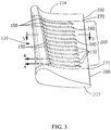
- cooling member 120 may be formed as a first segment 260 including a plurality of cooling channels 130 and at least one cooling cavity 490 and at least one second segment 280 optionally including a plurality of cooling cavities 590. As shown in FIGS. 2 and 3 , the at least one cooling cavity 490 of the first segment 260 may be aligned with the at least one cooling cavity 590 of the second cavity.
- the first segment 260 may be joined to the at least one second segment 280 using any suitable joining technique, shown by dashed lines 270 (see FIG. 3 ).
- Printed cooling member 120 includes a first end 222 and a second end 224. First end 222 or second end 224 may be attached to portion 110 using any suitable joining process, such as, but not limited to, brazing, welding or mechanical attachment means. As shown in FIG. 1 , first end 222 of cooling member 120 is attached to first end portion 114 and second end 224 of cooling member 120 is attached to second end portion 112 by welding or brazing, illustrated by a joint 140. Suitable examples of attaching include, but are not limited to, arc welding, beam welding, brazing, transient liquid phase (TLP) bonding, and diffusion bonding.
- TLP transient liquid phase
- cooling member 120 is a single printed piece including cooling channels 130, cooling cavities 490 and first openings 150 or supply passages and second openings 160 or exit passages formed therein.
- cooling member 120 is formed in steps. In one step, a first segment 260 including a plurality of cooling features 122 including cooling channels 130 and/or cooling cavities 490 and/or first and second openings 150 and 160 are printed. In another step, at least one second segment 280 is formed using three-dimensional printing or traditional casting techniques. As discussed above, first segment 260 may be formed using a first material and at least one second segment 280 may be formed using a second material. In one embodiment, first and second materials are the same.
- first and second materials are different.
- cooling member 120 is built by joining first segment 260 and at least one second segment 280 along joint lines 270 (see FIG. 3 ). Any suitable joining method may be used to join first segment 260 and at least one second segment 280, such as, but not limited to, arc welding, beam welding, brazing, transient liquid phase (TLP) bonding, and diffusion bonding.
- TLP transient liquid phase
- first openings 150 of supply passages from cooling cavity 490 to cooling channel 130 and second openings 160 or exit passages for coolant to leave channel 130 may also be printed into cooling member 120 or first segment 260 of cooling member 120.
- First openings 150 or inlets may be attached to cooling channel cavities 490 running throughout the length of component 100.
- First openings 150 and second openings 160 are interconnected by cooling channels 130.
- second openings 160 may be cylindrical holes but could also be shaped holes to enable coolant exiting the cooling channel 130 to provide film coverage to the downstream portion of the component.
- Second openings 160 or exit passages may also be trenches where coolant from one or more cooling channels 130 enters to spread along the trench and then exit the trench as film (see FIG. 1 ).
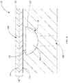
- using three-dimensional printing allows the at least one cooling channel 130 to be located at a distance 350 within a range of about 127 micrometers (0.005 inches) to about 762 micrometers (0.030 inches) from surface 322 of cooling member 120 of component 100.
- three-dimensional printing allows the at least one cooling channel 130 to be located at a distance 350 of at least less than about 508 micrometers (0.020 inches) from the surface 322 of cooling member 120 of component 100 (see FIG. 5 ).
- Distance 350 between cooling channel 130 and surface 322 of component 100 may be up to at least less than or as little as about 127 micrometers (0.005 inches).
- Distance 350 between cooling channel 130 and surface 322 of component 100 may be constant throughout cooling channel 130 length in component 100.
- distance 350 may be varied throughout length of cooling channel 130 in component 100 (see FIG. 4 ).
- Distance 350 may be from about 127 micrometers (0.005 inches) to about 1524 micrometers (0.060 inches), or alternatively about 254 micrometers (0.010 inches) to about 1270 micrometers, or alternatively about 254 micrometers (0.010 inches) to about 1016 micrometers, or alternatively about 254 micrometers (0.010 inches) to about 508 micrometers (0.020 inches), or alternatively less than about 508 micrometers (0.020 inches), or alternatively about 254 micrometers (0.010 inches) or alternatively about 127 micrometers (0.005 inches).
- typical casting methods used to form a component with cooling channels will have cooling channels located at about 2540 micrometers (0.100 inches) from surface.
- cooling channel 130 in cooling member 120 or at least one portion 110 reduces manufacturing steps and saves time and resources because cooling channels do not need to be drilled into the surface of component.
- Printing cooling member 120 or at least one portion 110 with cooling channels 130 formed therein also reduces manufacturing steps and time and resources because open cooling channels do not need to be closed using insert plates.
- the three-dimensional printing processes also allows the geometry (length, width, height, and depth) of the cooling channels 130 and at least one fluid pathway 360 therein to be varied along the length of cooling channel 130 within cooling member 120.
- cooling channel 130 may constrict or narrow in some areas or widen in other areas to match the cooling or heating local demands of component 100.
- Cooling channel 130 dimensions may be changed as necessary and the dimensions do not need to be constant from one end to another.
- cooling channel 130 may be a semi-circle having a width and depth of about 254 micrometers (0.010 inches) to about 2540 micrometers (0.100 inches) or alternatively about 762 micrometers (0.030 inches) to about 1524 micrometers (0.060 inches).
- an optional step of hot isostatic pressing (HIP) and/or solution heat-treating is performed to strengthen the printed cooling member 120 or at least one portion 110.
- HIP hot isostatic pressing
- internal defects such as porosity and micro fissures are closed or healed due to the temperature and applied pressure.
- solution heat treatment all deleterious precipitates are put into solution in the material matrix thereby providing the best properties.
- surface 322 may be coated with a protective coating 340.
- Protective coating 340 may include any number of layers, such as, but not limited to a bond coating 342 and thermal barrier coating 344 applied to bond coating 342.
- Protective coating 340 may be applied prior to joining cooling member 120 to at least one portion 110.
- Protective coating 340 may be applied after cooling member 120 is jointed to at least one portion 110 by welding, brazing or other suitable mechanical joining means.
- Transporting a fluid through at least one fluid pathway 360 defined by at least one cooling channel 130 within the component alters, cools, or heats surface 322 of component 100.
- the changes in geometry may be designed so as to maximize or minimize the alteration of temperature at any particular location along the length of at least one cooling channel 130 in component 100.
- the changes in geometry may enable highly specific manipulation of the thermal characteristics of surface 322 by at least one cooling channel 130.
- the geometry changes may enable the modification of thermal management properties of a component design with minimized cost and time compared to methods and articles that do not include one or more of the features disclosed herein.
- At least one cooling channel 130 may include at least one feature to disrupt laminar flow of a fluid through the at least one fluid pathway 360.
- the at least one feature to disrupt laminar flow may include turbulators 406, which mix the fluid in the at least one fluid pathway 360 from the middle to the sides and from the sides to the middle, making the at least one fluid pathway 360 effectively longer.
- Turbulators 406 may also increase the surface area of at least one cooling channel 130, which increases heat transfer from or to the fluid flowing through the at least one fluid pathway 360 to or from the substrate 322.
- Suitable examples of turbulators 406 include, but are not limited to, fin 410 and bumps 412.
- Turbulators 406 may be of any suitable shape or size, and may be included on the at least one inner surface of cooling channel 130 in any suitable arrangement or spacing to achieve the desired effect. Turbulators 406 may be formed within at least one cooling channel 130 using a three-dimensional printing process, resulting in a single homogeneous piece.
- the method includes forming at least one portion 110 of component 100 (see FIG. 1 ).
- the method includes printing a cooling member 120 (see FIG. 1 ) or first segment 260 and at least one second segment 280 and building cooling member 120 of component 100 (see FIGS. 2 and 3 ).
- the method includes attaching the at least one portion 110 to cooling member 120 of component 100 (see FIG. 1 ).
- the method includes transporting a fluid through the at least one fluid pathway 360 defined by the at least one cooling channel 130 within component 100 to cool component 100 (see FIGS. 4 and 6 ).
Landscapes
- Engineering & Computer Science (AREA)
- Manufacturing & Machinery (AREA)
- Mechanical Engineering (AREA)
- Chemical & Material Sciences (AREA)
- Materials Engineering (AREA)
- Composite Materials (AREA)
- General Engineering & Computer Science (AREA)
- Plasma & Fusion (AREA)
- Physics & Mathematics (AREA)
- Turbine Rotor Nozzle Sealing (AREA)
- Powder Metallurgy (AREA)
- Butt Welding And Welding Of Specific Article (AREA)
- Pressure Welding/Diffusion-Bonding (AREA)
- Laser Beam Processing (AREA)
- Coating By Spraying Or Casting (AREA)
- Application Of Or Painting With Fluid Materials (AREA)
Claims (9)
- Verfahren zum Herstellen einer Gasturbinenkomponente (100), umfassend:Drucken mindestens eines Kühlelementabschnitts (120) der Komponente, wobei der Kühlelementabschnitt (120) mindestens ein Kühlmerkmal (122) einschließt, das mindestens einen Kühlhohlraum (490) und mindestens einen Kühlkanal (130) umfasst, wobei der mindestens eine Kühlhohlraum von einem ersten Ende (222) zu einem zweiten Ende (224) des Kühlelements verläuft und der mindestens eine Kühlkanal (130) benachbart zu und sich entlang einer Länge einer Oberfläche (322) des Kühlelements und in einem Abstand von etwa 127 (0,005 Zoll) bis etwa 762 Mikrometer (0,030 Zoll) von der Oberfläche (322) des Kühlelements erstreckt, wobei der mindestens eine Kühlkanal (130) durch eine erste Endöffnung (150) und eine zweite Endöffnung (160) mit einem oder mehreren des mindestens einen Kühlhohlraums (490) und der Oberfläche (322) des Kühlelements verbunden ist, um einen Fluidweg dazwischen bereitzustellen; und separates Bilden mindestens eines oder mehrerer zusätzlicher Abschnitte der Komponente, wobei mindestens einer des einen oder der mehreren zusätzlichen Abschnitte zur Befestigung an dem Kühlelement ausgelegt ist; undBefestigen mindestens eines des einen oder der mehreren zusätzlichen Abschnitte (110) der Komponente an dem Kühlelementabschnitt (120) der Komponente (100);wobei der Schritt des Druckens einen dreidimensionalen Druckprozess verwendet.
- Verfahren nach Anspruch 1, wobei der mindestens eine des einen oder der mehreren zusätzlichen Abschnitte der Komponente ferner mindestens einen Kühlhohlraum aufweist, der sich bei Befestigung daran mit dem mindestens einen Kühlhohlraum des Kühlelementabschnitts (120) ausrichtet.
- Verfahren nach Anspruch 1 oder 2, wobei der Schritt des Bildens mindestens eines oder mehrerer zusätzlicher Abschnitte der Komponente ein Gießen oder dreidimensionales Drucken umfasst.
- Verfahren nach einem der vorstehenden Ansprüche, wobei der Schritt des Befestigens Schweißen, Löten, Verbinden mit transienter flüssiger Phase (TLP), Diffusionsverbinden, mechanisches Befestigen oder Kombinationen davon umfasst.
- Verfahren nach einem der vorstehenden Ansprüche, wobei der mindestens eine des einen oder der mehreren zusätzlichen Abschnitte (110) aus einem ersten Material ausgewählt ist und das Kühlelement (120) aus einem zweiten Material ausgewählt ist, wobei das erste Material das gleiche wie das zweite Material ist oder davon verschieden ist.
- Verfahren nach einem der vorstehenden Ansprüche, wobei das erste Material ausgewählt ist aus Nickel, Eisen, Kobalt, Chrom, Molybdän, Aluminium, Titan, Edelstahl, Superlegierungen auf Nickelbasis, Kobalt-Superlegierungen oder Kombinationen davon.
- Verfahren nach einem der vorstehenden Ansprüche, wobei das zweite Material ausgewählt ist aus Nickel, Eisen, Kobalt, Chrom, Molybdän, Aluminium, Titan, Edelstahl, Superlegierungen auf Nickelbasis, Kobalt-Superlegierungen oder Kombinationen davon.
- Verfahren nach einem der vorstehenden Ansprüche, wobei der mindestens eine Kühlkanal (130) über das gesamte Kühlelement (120) eine variierende Geometrie aufweist.
- Verfahren nach einem der vorstehenden Ansprüche, ferner umfassend das Aufbringen mindestens einer Schutzbeschichtung nach dem Schritt des Befestigens.
Applications Claiming Priority (1)
| Application Number | Priority Date | Filing Date | Title |
|---|---|---|---|
| US14/037,887 US20150086408A1 (en) | 2013-09-26 | 2013-09-26 | Method of manufacturing a component and thermal management process |
Publications (3)
| Publication Number | Publication Date |
|---|---|
| EP2853323A2 EP2853323A2 (de) | 2015-04-01 |
| EP2853323A3 EP2853323A3 (de) | 2015-09-16 |
| EP2853323B1 true EP2853323B1 (de) | 2021-02-17 |
Family
ID=51618986
Family Applications (1)
| Application Number | Title | Priority Date | Filing Date |
|---|---|---|---|
| EP14185104.8A Active EP2853323B1 (de) | 2013-09-26 | 2014-09-17 | Verfahren zur Herstellung einer Turbinenkomponente |
Country Status (4)
| Country | Link |
|---|---|
| US (1) | US20150086408A1 (de) |
| EP (1) | EP2853323B1 (de) |
| JP (1) | JP6687318B2 (de) |
| CN (1) | CN104511725A (de) |
Families Citing this family (57)
| Publication number | Priority date | Publication date | Assignee | Title |
|---|---|---|---|---|
| US9260788B2 (en) * | 2012-10-30 | 2016-02-16 | General Electric Company | Reinforced articles and methods of making the same |
| US9624779B2 (en) * | 2013-10-15 | 2017-04-18 | General Electric Company | Thermal management article and method of forming the same, and method of thermal management of a substrate |
| US9849510B2 (en) | 2015-04-16 | 2017-12-26 | General Electric Company | Article and method of forming an article |
| DE102015209583A1 (de) | 2015-05-26 | 2016-12-01 | Siemens Aktiengesellschaft | Molybdän-Silizium-Borlegierung und Verfahren zur Herstellung sowie Bauteil |
| US9976441B2 (en) | 2015-05-29 | 2018-05-22 | General Electric Company | Article, component, and method of forming an article |
| DE102015210744A1 (de) * | 2015-06-12 | 2016-12-15 | Siemens Aktiengesellschaft | Verfahren zum Fertigen einer Turbinenschaufel |
| US9938899B2 (en) | 2015-06-15 | 2018-04-10 | General Electric Company | Hot gas path component having cast-in features for near wall cooling |
| US9828915B2 (en) * | 2015-06-15 | 2017-11-28 | General Electric Company | Hot gas path component having near wall cooling features |
| US9897006B2 (en) | 2015-06-15 | 2018-02-20 | General Electric Company | Hot gas path component cooling system having a particle collection chamber |
| US9970302B2 (en) * | 2015-06-15 | 2018-05-15 | General Electric Company | Hot gas path component trailing edge having near wall cooling features |
| US9850763B2 (en) * | 2015-07-29 | 2017-12-26 | General Electric Company | Article, airfoil component and method for forming article |
| US10337343B2 (en) | 2015-08-13 | 2019-07-02 | General Electric Company | Turbine component surface cooling system with passive flow modulation |
| US10087776B2 (en) | 2015-09-08 | 2018-10-02 | General Electric Company | Article and method of forming an article |
| US10739087B2 (en) * | 2015-09-08 | 2020-08-11 | General Electric Company | Article, component, and method of forming an article |
| US10253986B2 (en) | 2015-09-08 | 2019-04-09 | General Electric Company | Article and method of forming an article |
| US10010937B2 (en) | 2015-11-09 | 2018-07-03 | General Electric Company | Additive manufacturing method for making overhanging tabs in cooling holes |
| EP3176371A1 (de) * | 2015-12-03 | 2017-06-07 | Siemens Aktiengesellschaft | Komponente für eine flüssigkeitsströmungsmaschine und verfahren |
| US10053988B2 (en) * | 2015-12-10 | 2018-08-21 | General Electric Company | Article and method of forming an article |
| US10137499B2 (en) * | 2015-12-17 | 2018-11-27 | General Electric Company | Method and assembly for forming components having an internal passage defined therein |
| US10583532B2 (en) * | 2015-12-28 | 2020-03-10 | General Electric Company | Metal additive manufacturing using gas mixture including oxygen |
| US20190003332A1 (en) * | 2015-12-30 | 2019-01-03 | Siemens Aktiengesellschaft | Gas turbine, sealing cover, sealing telemetry assembly, and manufacturing method thereof |
| US10704395B2 (en) * | 2016-05-10 | 2020-07-07 | General Electric Company | Airfoil with cooling circuit |
| US10590776B2 (en) | 2016-06-06 | 2020-03-17 | General Electric Company | Turbine component and methods of making and cooling a turbine component |
| US10502058B2 (en) | 2016-07-08 | 2019-12-10 | General Electric Company | Coupon for hot gas path component having manufacturing assist features |
| US10443399B2 (en) | 2016-07-22 | 2019-10-15 | General Electric Company | Turbine vane with coupon having corrugated surface(s) |
| US10465520B2 (en) | 2016-07-22 | 2019-11-05 | General Electric Company | Blade with corrugated outer surface(s) |
| US10465525B2 (en) | 2016-07-22 | 2019-11-05 | General Electric Company | Blade with internal rib having corrugated surface(s) |
| US10436037B2 (en) | 2016-07-22 | 2019-10-08 | General Electric Company | Blade with parallel corrugated surfaces on inner and outer surfaces |
| US10450868B2 (en) | 2016-07-22 | 2019-10-22 | General Electric Company | Turbine rotor blade with coupon having corrugated surface(s) |
| DE102016214208B4 (de) * | 2016-08-02 | 2018-03-29 | Siemens Aktiengesellschaft | Verfahren zur Herstellung einer Kanalstruktur und Komponente |
| US20180036796A1 (en) * | 2016-08-08 | 2018-02-08 | Honeywell International Inc. | System and method for forming directionally solidified part from additively manufactured article |
| US10920295B2 (en) * | 2016-11-01 | 2021-02-16 | The Nanosteel Company, Inc. | 3D printable hard ferrous metallic alloys for powder bed fusion |
| US10953465B2 (en) | 2016-11-01 | 2021-03-23 | The Nanosteel Company, Inc. | 3D printable hard ferrous metallic alloys for powder bed fusion |
| US20180161866A1 (en) | 2016-12-13 | 2018-06-14 | General Electric Company | Multi-piece integrated core-shell structure for making cast component |
| US10807154B2 (en) | 2016-12-13 | 2020-10-20 | General Electric Company | Integrated casting core-shell structure for making cast component with cooling holes in inaccessible locations |
| US11813669B2 (en) | 2016-12-13 | 2023-11-14 | General Electric Company | Method for making an integrated core-shell structure |
| US10829845B2 (en) * | 2017-01-06 | 2020-11-10 | General Electric Company | Selective thermal coating of cooling holes with air flow |
| CN106703899B (zh) * | 2017-01-23 | 2019-08-23 | 中国航发沈阳发动机研究所 | 高压涡轮转子叶片前缘冲击冷却结构及具有其的发动机 |
| WO2018160922A2 (en) * | 2017-03-03 | 2018-09-07 | Roland Zellweger | Fixturing collet arrangements and fabrication methods |
| US10610917B2 (en) * | 2017-03-23 | 2020-04-07 | Ford Motor Company | 3D-printed conformal cooling for hot stamping casted die inserts |
| US10232444B2 (en) * | 2017-04-03 | 2019-03-19 | General Electric Company | Clad article and method for forming clad article |
| US10583489B2 (en) * | 2017-04-26 | 2020-03-10 | General Electric Company | Method of providing cooling structure for a component |
| WO2018198871A1 (ja) * | 2017-04-27 | 2018-11-01 | 株式会社神戸製鋼所 | 積層造形部品の接合方法及び構造体、並びに積層造形部品 |
| JP6898187B2 (ja) * | 2017-04-27 | 2021-07-07 | 株式会社神戸製鋼所 | 積層造形部品の接合方法及び構造体、並びに積層造形部品 |
| US10494948B2 (en) * | 2017-05-09 | 2019-12-03 | General Electric Company | Impingement insert |
| US20190040749A1 (en) * | 2017-08-01 | 2019-02-07 | United Technologies Corporation | Method of fabricating a turbine blade |
| JP6349449B1 (ja) * | 2017-09-19 | 2018-06-27 | 三菱日立パワーシステムズ株式会社 | タービン翼の製造方法、及びタービン翼 |
| US10781697B2 (en) * | 2017-12-05 | 2020-09-22 | Raytheon Technologies Corporation | Double wall turbine gas turbine engine blade cooling configuration |
| US10808548B2 (en) * | 2017-12-05 | 2020-10-20 | Raytheon Technologies Corporation | Double wall turbine gas turbine engine blade cooling configuration |
| US10487771B2 (en) | 2018-01-15 | 2019-11-26 | Ford Global Technologies, Llc | Cylinder head of an internal combustion engine |
| US12240062B2 (en) | 2018-09-04 | 2025-03-04 | Swagelok Company | Weld collet |
| US10767492B2 (en) | 2018-12-18 | 2020-09-08 | General Electric Company | Turbine engine airfoil |
| JP7467062B2 (ja) * | 2019-10-15 | 2024-04-15 | 東京エレクトロン株式会社 | シリコン部材の製造方法及び造形装置 |
| DE102020103848A1 (de) * | 2020-02-14 | 2021-08-19 | Netzsch-Feinmahltechnik Gmbh | Temperiertes Bauteil und Verfahren zur Herstellung eines temperierten Bauteils |
| KR102545934B1 (ko) * | 2021-09-02 | 2023-06-22 | 경상국립대학교산학협력단 | 저온 인장특성이 우수한 Inconel 718 합금 적층 조형물 제조방법 및 이를 이용한 Inconel 718 합금 적층 조형물 |
| JP2024001478A (ja) * | 2022-06-22 | 2024-01-10 | 三菱重工業株式会社 | タービン部品の製造方法 |
| US11572803B1 (en) | 2022-08-01 | 2023-02-07 | General Electric Company | Turbine airfoil with leading edge cooling passage(s) coupled via plenum to film cooling holes, and related method |
Citations (1)
| Publication number | Priority date | Publication date | Assignee | Title |
|---|---|---|---|---|
| EP2325440A2 (de) * | 2009-11-23 | 2011-05-25 | United Technologies Corporation | Turbinenschaufel mit serpentinenförmigen Mikrokühlkanälen |
Family Cites Families (14)
| Publication number | Priority date | Publication date | Assignee | Title |
|---|---|---|---|---|
| US4055705A (en) * | 1976-05-14 | 1977-10-25 | The United States Of America As Represented By The Administrator Of The National Aeronautics And Space Administration | Thermal barrier coating system |
| US6471479B2 (en) * | 2001-02-23 | 2002-10-29 | General Electric Company | Turbine airfoil with single aft flowing three pass serpentine cooling circuit |
| ATE428423T1 (de) * | 2002-08-20 | 2009-05-15 | Bristol Myers Squibb Co | Aripiprazol-komplex-formulierung und verfahren |
| DE102007054723B4 (de) * | 2007-11-14 | 2015-05-28 | Cl Schutzrechtsverwaltungs Gmbh | Formteil |
| US8066483B1 (en) * | 2008-12-18 | 2011-11-29 | Florida Turbine Technologies, Inc. | Turbine airfoil with non-parallel pin fins |
| US8109726B2 (en) * | 2009-01-19 | 2012-02-07 | Siemens Energy, Inc. | Turbine blade with micro channel cooling system |
| US8894367B2 (en) * | 2009-08-06 | 2014-11-25 | Siemens Energy, Inc. | Compound cooling flow turbulator for turbine component |
| US8449254B2 (en) * | 2010-03-29 | 2013-05-28 | United Technologies Corporation | Branched airfoil core cooling arrangement |
| US9175568B2 (en) * | 2010-06-22 | 2015-11-03 | Honeywell International Inc. | Methods for manufacturing turbine components |
| DE102011080187A1 (de) * | 2011-08-01 | 2013-02-07 | Siemens Aktiengesellschaft | Verfahren zum Erzeugen einer Schaufel für eine Strömungskraftmaschine und Schaufel für eine Strömungskraftmaschine |
| US9266170B2 (en) * | 2012-01-27 | 2016-02-23 | Honeywell International Inc. | Multi-material turbine components |
| US8500401B1 (en) * | 2012-07-02 | 2013-08-06 | Florida Turbine Technologies, Inc. | Turbine blade with counter flowing near wall cooling channels |
| US20140126995A1 (en) * | 2012-11-06 | 2014-05-08 | General Electric Company | Microchannel cooled turbine component and method of forming a microchannel cooled turbine component |
| US9109451B1 (en) * | 2012-11-20 | 2015-08-18 | Florida Turbine Technologies, Inc. | Turbine blade with micro sized near wall cooling channels |
-
2013
- 2013-09-26 US US14/037,887 patent/US20150086408A1/en not_active Abandoned
-
2014
- 2014-09-17 EP EP14185104.8A patent/EP2853323B1/de active Active
- 2014-09-22 JP JP2014192076A patent/JP6687318B2/ja active Active
- 2014-09-26 CN CN201410501219.XA patent/CN104511725A/zh active Pending
Patent Citations (1)
| Publication number | Priority date | Publication date | Assignee | Title |
|---|---|---|---|---|
| EP2325440A2 (de) * | 2009-11-23 | 2011-05-25 | United Technologies Corporation | Turbinenschaufel mit serpentinenförmigen Mikrokühlkanälen |
Also Published As
| Publication number | Publication date |
|---|---|
| JP6687318B2 (ja) | 2020-04-22 |
| JP2015067902A (ja) | 2015-04-13 |
| EP2853323A3 (de) | 2015-09-16 |
| CN104511725A (zh) | 2015-04-15 |
| EP2853323A2 (de) | 2015-04-01 |
| US20150086408A1 (en) | 2015-03-26 |
Similar Documents
| Publication | Publication Date | Title |
|---|---|---|
| EP2853323B1 (de) | Verfahren zur Herstellung einer Turbinenkomponente | |
| US9624779B2 (en) | Thermal management article and method of forming the same, and method of thermal management of a substrate | |
| US9482249B2 (en) | Three-dimensional printing process, swirling device and thermal management process | |
| EP2876260B1 (de) | Hintere rahmenanordnung einer gasturbine und herstellungsverfahren | |
| EP3255247B1 (de) | Turbinenkomponente und verfahren zur herstellung und kühlung einer turbinenkomponente | |
| JP7114213B2 (ja) | 物品及び物品を形成する方法 | |
| US9434017B2 (en) | Braze methods and components with heat resistant materials | |
| EP2728119B1 (de) | Mikrokanalgekühltes Turbinenbauteil und Verfahren zum Herstellen eines mikrokanalgekühlten Turbinenbauteils | |
| JP6994822B2 (ja) | 物品及び物品を形成する方法 | |
| EP3084138B1 (de) | Gasturbinenschaufel mit keramikspitze und kühlanordnung | |
| JP2017115861A (ja) | 物品及び物品を形成する方法 | |
| KR102889298B1 (ko) | 적층 제조에 의한 인접 휠 공간 부분들 사이의 냉각제 전달 통로를 갖는 엔젤 윙 시일을 갖는 터빈 로터 블레이드 | |
| JP2014177938A (ja) | マイクロ冷却レーザ堆積材料層を備えた構成要素並びにその製造方法 | |
| US10174414B2 (en) | Manufactured article and method | |
| JP2021116808A (ja) | 付加製造による非線形冷却通路を有するプラットフォームを備えたタービンロータブレード | |
| US10053988B2 (en) | Article and method of forming an article | |
| JP2014139428A (ja) | リソグラフィ成形技術を使用して構成要素に表面冷却チャネルを作成する方法 | |
| WO2017222920A1 (en) | Methods for repairing film holes in a surface | |
| JP6608589B2 (ja) | 冷却チャンネルを形成および成形するための方法、ならびに関連製品 | |
| JP2021116807A (ja) | 付加製造による一体型インピンジメントスリーブを備えたタービンロータブレード | |
| US7541561B2 (en) | Process of microwave heating of powder materials | |
| JP2021116809A (ja) | 付加製造による格子支持構造を有する中空マウントを備えたタービンロータブレード根元 | |
| JP2023154992A (ja) | タービン部材の製造方法およびタービン部材の補修方法 |
Legal Events
| Date | Code | Title | Description |
|---|---|---|---|
| PUAI | Public reference made under article 153(3) epc to a published international application that has entered the european phase |
Free format text: ORIGINAL CODE: 0009012 |
|
| 17P | Request for examination filed |
Effective date: 20140917 |
|
| AK | Designated contracting states |
Kind code of ref document: A2 Designated state(s): AL AT BE BG CH CY CZ DE DK EE ES FI FR GB GR HR HU IE IS IT LI LT LU LV MC MK MT NL NO PL PT RO RS SE SI SK SM TR |
|
| AX | Request for extension of the european patent |
Extension state: BA ME |
|
| PUAL | Search report despatched |
Free format text: ORIGINAL CODE: 0009013 |
|
| AK | Designated contracting states |
Kind code of ref document: A3 Designated state(s): AL AT BE BG CH CY CZ DE DK EE ES FI FR GB GR HR HU IE IS IT LI LT LU LV MC MK MT NL NO PL PT RO RS SE SI SK SM TR |
|
| AX | Request for extension of the european patent |
Extension state: BA ME |
|
| RIC1 | Information provided on ipc code assigned before grant |
Ipc: B22F 7/06 20060101ALI20150811BHEP Ipc: B22F 7/08 20060101ALI20150811BHEP Ipc: B22F 5/04 20060101ALI20150811BHEP Ipc: B22F 3/105 20060101AFI20150811BHEP Ipc: B22F 5/10 20060101ALI20150811BHEP Ipc: F01D 5/18 20060101ALI20150811BHEP |
|
| R17P | Request for examination filed (corrected) |
Effective date: 20160316 |
|
| RBV | Designated contracting states (corrected) |
Designated state(s): AL AT BE BG CH CY CZ DE DK EE ES FI FR GB GR HR HU IE IS IT LI LT LU LV MC MK MT NL NO PL PT RO RS SE SI SK SM TR |
|
| STAA | Information on the status of an ep patent application or granted ep patent |
Free format text: STATUS: EXAMINATION IS IN PROGRESS |
|
| 17Q | First examination report despatched |
Effective date: 20180817 |
|
| RIC1 | Information provided on ipc code assigned before grant |
Ipc: B22F 7/06 20060101ALI20200619BHEP Ipc: B22F 5/04 20060101ALI20200619BHEP Ipc: B22F 3/105 20060101AFI20200619BHEP Ipc: B33Y 80/00 20150101ALI20200619BHEP Ipc: F01D 5/18 20060101ALI20200619BHEP Ipc: B22F 5/10 20060101ALI20200619BHEP Ipc: B22F 7/08 20060101ALI20200619BHEP Ipc: B33Y 10/00 20150101ALI20200619BHEP |
|
| GRAP | Despatch of communication of intention to grant a patent |
Free format text: ORIGINAL CODE: EPIDOSNIGR1 |
|
| STAA | Information on the status of an ep patent application or granted ep patent |
Free format text: STATUS: GRANT OF PATENT IS INTENDED |
|
| INTG | Intention to grant announced |
Effective date: 20200814 |
|
| GRAS | Grant fee paid |
Free format text: ORIGINAL CODE: EPIDOSNIGR3 |
|
| GRAA | (expected) grant |
Free format text: ORIGINAL CODE: 0009210 |
|
| STAA | Information on the status of an ep patent application or granted ep patent |
Free format text: STATUS: THE PATENT HAS BEEN GRANTED |
|
| AK | Designated contracting states |
Kind code of ref document: B1 Designated state(s): AL AT BE BG CH CY CZ DE DK EE ES FI FR GB GR HR HU IE IS IT LI LT LU LV MC MK MT NL NO PL PT RO RS SE SI SK SM TR |
|
| REG | Reference to a national code |
Ref country code: GB Ref legal event code: FG4D |
|
| REG | Reference to a national code |
Ref country code: CH Ref legal event code: EP |
|
| REG | Reference to a national code |
Ref country code: DE Ref legal event code: R096 Ref document number: 602014074781 Country of ref document: DE |
|
| REG | Reference to a national code |
Ref country code: AT Ref legal event code: REF Ref document number: 1360831 Country of ref document: AT Kind code of ref document: T Effective date: 20210315 |
|
| REG | Reference to a national code |
Ref country code: IE Ref legal event code: FG4D |
|
| REG | Reference to a national code |
Ref country code: LT Ref legal event code: MG9D |
|
| REG | Reference to a national code |
Ref country code: NL Ref legal event code: MP Effective date: 20210217 |
|
| PG25 | Lapsed in a contracting state [announced via postgrant information from national office to epo] |
Ref country code: NO Free format text: LAPSE BECAUSE OF FAILURE TO SUBMIT A TRANSLATION OF THE DESCRIPTION OR TO PAY THE FEE WITHIN THE PRESCRIBED TIME-LIMIT Effective date: 20210517 Ref country code: BG Free format text: LAPSE BECAUSE OF FAILURE TO SUBMIT A TRANSLATION OF THE DESCRIPTION OR TO PAY THE FEE WITHIN THE PRESCRIBED TIME-LIMIT Effective date: 20210517 Ref country code: HR Free format text: LAPSE BECAUSE OF FAILURE TO SUBMIT A TRANSLATION OF THE DESCRIPTION OR TO PAY THE FEE WITHIN THE PRESCRIBED TIME-LIMIT Effective date: 20210217 Ref country code: FI Free format text: LAPSE BECAUSE OF FAILURE TO SUBMIT A TRANSLATION OF THE DESCRIPTION OR TO PAY THE FEE WITHIN THE PRESCRIBED TIME-LIMIT Effective date: 20210217 Ref country code: GR Free format text: LAPSE BECAUSE OF FAILURE TO SUBMIT A TRANSLATION OF THE DESCRIPTION OR TO PAY THE FEE WITHIN THE PRESCRIBED TIME-LIMIT Effective date: 20210518 Ref country code: LT Free format text: LAPSE BECAUSE OF FAILURE TO SUBMIT A TRANSLATION OF THE DESCRIPTION OR TO PAY THE FEE WITHIN THE PRESCRIBED TIME-LIMIT Effective date: 20210217 Ref country code: PT Free format text: LAPSE BECAUSE OF FAILURE TO SUBMIT A TRANSLATION OF THE DESCRIPTION OR TO PAY THE FEE WITHIN THE PRESCRIBED TIME-LIMIT Effective date: 20210617 |
|
| REG | Reference to a national code |
Ref country code: AT Ref legal event code: MK05 Ref document number: 1360831 Country of ref document: AT Kind code of ref document: T Effective date: 20210217 |
|
| PG25 | Lapsed in a contracting state [announced via postgrant information from national office to epo] |
Ref country code: SE Free format text: LAPSE BECAUSE OF FAILURE TO SUBMIT A TRANSLATION OF THE DESCRIPTION OR TO PAY THE FEE WITHIN THE PRESCRIBED TIME-LIMIT Effective date: 20210217 Ref country code: PL Free format text: LAPSE BECAUSE OF FAILURE TO SUBMIT A TRANSLATION OF THE DESCRIPTION OR TO PAY THE FEE WITHIN THE PRESCRIBED TIME-LIMIT Effective date: 20210217 Ref country code: LV Free format text: LAPSE BECAUSE OF FAILURE TO SUBMIT A TRANSLATION OF THE DESCRIPTION OR TO PAY THE FEE WITHIN THE PRESCRIBED TIME-LIMIT Effective date: 20210217 Ref country code: NL Free format text: LAPSE BECAUSE OF FAILURE TO SUBMIT A TRANSLATION OF THE DESCRIPTION OR TO PAY THE FEE WITHIN THE PRESCRIBED TIME-LIMIT Effective date: 20210217 Ref country code: RS Free format text: LAPSE BECAUSE OF FAILURE TO SUBMIT A TRANSLATION OF THE DESCRIPTION OR TO PAY THE FEE WITHIN THE PRESCRIBED TIME-LIMIT Effective date: 20210217 |
|
| PG25 | Lapsed in a contracting state [announced via postgrant information from national office to epo] |
Ref country code: IS Free format text: LAPSE BECAUSE OF FAILURE TO SUBMIT A TRANSLATION OF THE DESCRIPTION OR TO PAY THE FEE WITHIN THE PRESCRIBED TIME-LIMIT Effective date: 20210617 |
|
| PG25 | Lapsed in a contracting state [announced via postgrant information from national office to epo] |
Ref country code: AT Free format text: LAPSE BECAUSE OF FAILURE TO SUBMIT A TRANSLATION OF THE DESCRIPTION OR TO PAY THE FEE WITHIN THE PRESCRIBED TIME-LIMIT Effective date: 20210217 Ref country code: CZ Free format text: LAPSE BECAUSE OF FAILURE TO SUBMIT A TRANSLATION OF THE DESCRIPTION OR TO PAY THE FEE WITHIN THE PRESCRIBED TIME-LIMIT Effective date: 20210217 Ref country code: EE Free format text: LAPSE BECAUSE OF FAILURE TO SUBMIT A TRANSLATION OF THE DESCRIPTION OR TO PAY THE FEE WITHIN THE PRESCRIBED TIME-LIMIT Effective date: 20210217 Ref country code: SM Free format text: LAPSE BECAUSE OF FAILURE TO SUBMIT A TRANSLATION OF THE DESCRIPTION OR TO PAY THE FEE WITHIN THE PRESCRIBED TIME-LIMIT Effective date: 20210217 |
|
| REG | Reference to a national code |
Ref country code: DE Ref legal event code: R097 Ref document number: 602014074781 Country of ref document: DE |
|
| PG25 | Lapsed in a contracting state [announced via postgrant information from national office to epo] |
Ref country code: SK Free format text: LAPSE BECAUSE OF FAILURE TO SUBMIT A TRANSLATION OF THE DESCRIPTION OR TO PAY THE FEE WITHIN THE PRESCRIBED TIME-LIMIT Effective date: 20210217 Ref country code: DK Free format text: LAPSE BECAUSE OF FAILURE TO SUBMIT A TRANSLATION OF THE DESCRIPTION OR TO PAY THE FEE WITHIN THE PRESCRIBED TIME-LIMIT Effective date: 20210217 Ref country code: ES Free format text: LAPSE BECAUSE OF FAILURE TO SUBMIT A TRANSLATION OF THE DESCRIPTION OR TO PAY THE FEE WITHIN THE PRESCRIBED TIME-LIMIT Effective date: 20210217 Ref country code: RO Free format text: LAPSE BECAUSE OF FAILURE TO SUBMIT A TRANSLATION OF THE DESCRIPTION OR TO PAY THE FEE WITHIN THE PRESCRIBED TIME-LIMIT Effective date: 20210217 |
|
| PLBE | No opposition filed within time limit |
Free format text: ORIGINAL CODE: 0009261 |
|
| STAA | Information on the status of an ep patent application or granted ep patent |
Free format text: STATUS: NO OPPOSITION FILED WITHIN TIME LIMIT |
|
| 26N | No opposition filed |
Effective date: 20211118 |
|
| PG25 | Lapsed in a contracting state [announced via postgrant information from national office to epo] |
Ref country code: AL Free format text: LAPSE BECAUSE OF FAILURE TO SUBMIT A TRANSLATION OF THE DESCRIPTION OR TO PAY THE FEE WITHIN THE PRESCRIBED TIME-LIMIT Effective date: 20210217 |
|
| PG25 | Lapsed in a contracting state [announced via postgrant information from national office to epo] |
Ref country code: SI Free format text: LAPSE BECAUSE OF FAILURE TO SUBMIT A TRANSLATION OF THE DESCRIPTION OR TO PAY THE FEE WITHIN THE PRESCRIBED TIME-LIMIT Effective date: 20210217 |
|
| REG | Reference to a national code |
Ref country code: BE Ref legal event code: MM Effective date: 20210930 |
|
| PG25 | Lapsed in a contracting state [announced via postgrant information from national office to epo] |
Ref country code: IS Free format text: LAPSE BECAUSE OF FAILURE TO SUBMIT A TRANSLATION OF THE DESCRIPTION OR TO PAY THE FEE WITHIN THE PRESCRIBED TIME-LIMIT Effective date: 20210617 Ref country code: MC Free format text: LAPSE BECAUSE OF FAILURE TO SUBMIT A TRANSLATION OF THE DESCRIPTION OR TO PAY THE FEE WITHIN THE PRESCRIBED TIME-LIMIT Effective date: 20210217 |
|
| PG25 | Lapsed in a contracting state [announced via postgrant information from national office to epo] |
Ref country code: LU Free format text: LAPSE BECAUSE OF NON-PAYMENT OF DUE FEES Effective date: 20210917 Ref country code: IE Free format text: LAPSE BECAUSE OF NON-PAYMENT OF DUE FEES Effective date: 20210917 Ref country code: FR Free format text: LAPSE BECAUSE OF NON-PAYMENT OF DUE FEES Effective date: 20210930 Ref country code: BE Free format text: LAPSE BECAUSE OF NON-PAYMENT OF DUE FEES Effective date: 20210930 |
|
| PG25 | Lapsed in a contracting state [announced via postgrant information from national office to epo] |
Ref country code: HU Free format text: LAPSE BECAUSE OF FAILURE TO SUBMIT A TRANSLATION OF THE DESCRIPTION OR TO PAY THE FEE WITHIN THE PRESCRIBED TIME-LIMIT; INVALID AB INITIO Effective date: 20140917 |
|
| PG25 | Lapsed in a contracting state [announced via postgrant information from national office to epo] |
Ref country code: CY Free format text: LAPSE BECAUSE OF FAILURE TO SUBMIT A TRANSLATION OF THE DESCRIPTION OR TO PAY THE FEE WITHIN THE PRESCRIBED TIME-LIMIT Effective date: 20210217 |
|
| REG | Reference to a national code |
Ref country code: DE Ref legal event code: R081 Ref document number: 602014074781 Country of ref document: DE Owner name: GENERAL ELECTRIC TECHNOLOGY GMBH, CH Free format text: FORMER OWNER: GENERAL ELECTRIC COMPANY, SCHENECTADY, NY, US |
|
| REG | Reference to a national code |
Ref country code: GB Ref legal event code: 732E Free format text: REGISTERED BETWEEN 20240222 AND 20240228 |
|
| PG25 | Lapsed in a contracting state [announced via postgrant information from national office to epo] |
Ref country code: MK Free format text: LAPSE BECAUSE OF FAILURE TO SUBMIT A TRANSLATION OF THE DESCRIPTION OR TO PAY THE FEE WITHIN THE PRESCRIBED TIME-LIMIT Effective date: 20210217 |
|
| PG25 | Lapsed in a contracting state [announced via postgrant information from national office to epo] |
Ref country code: MT Free format text: LAPSE BECAUSE OF FAILURE TO SUBMIT A TRANSLATION OF THE DESCRIPTION OR TO PAY THE FEE WITHIN THE PRESCRIBED TIME-LIMIT Effective date: 20210217 |
|
| REG | Reference to a national code |
Ref country code: CH Ref legal event code: U11 Free format text: ST27 STATUS EVENT CODE: U-0-0-U10-U11 (AS PROVIDED BY THE NATIONAL OFFICE) Effective date: 20251001 |
|
| PGFP | Annual fee paid to national office [announced via postgrant information from national office to epo] |
Ref country code: DE Payment date: 20250820 Year of fee payment: 12 |
|
| PGFP | Annual fee paid to national office [announced via postgrant information from national office to epo] |
Ref country code: IT Payment date: 20250820 Year of fee payment: 12 |
|
| PGFP | Annual fee paid to national office [announced via postgrant information from national office to epo] |
Ref country code: GB Payment date: 20250822 Year of fee payment: 12 |
|
| PG25 | Lapsed in a contracting state [announced via postgrant information from national office to epo] |
Ref country code: TR Free format text: LAPSE BECAUSE OF FAILURE TO SUBMIT A TRANSLATION OF THE DESCRIPTION OR TO PAY THE FEE WITHIN THE PRESCRIBED TIME-LIMIT Effective date: 20210217 |
|
| PGFP | Annual fee paid to national office [announced via postgrant information from national office to epo] |
Ref country code: CH Payment date: 20251001 Year of fee payment: 12 |