EP2853347A2 - Outil d'ajustement et son procédé de fabrication - Google Patents
Outil d'ajustement et son procédé de fabrication Download PDFInfo
- Publication number
- EP2853347A2 EP2853347A2 EP14176364.9A EP14176364A EP2853347A2 EP 2853347 A2 EP2853347 A2 EP 2853347A2 EP 14176364 A EP14176364 A EP 14176364A EP 2853347 A2 EP2853347 A2 EP 2853347A2
- Authority
- EP
- European Patent Office
- Prior art keywords
- carrier
- abrasive particles
- dressing tool
- soldering
- fixed
- Prior art date
- Legal status (The legal status is an assumption and is not a legal conclusion. Google has not performed a legal analysis and makes no representation as to the accuracy of the status listed.)
- Withdrawn
Links
Images


Classifications
-
- B—PERFORMING OPERATIONS; TRANSPORTING
- B24—GRINDING; POLISHING
- B24B—MACHINES, DEVICES, OR PROCESSES FOR GRINDING OR POLISHING; DRESSING OR CONDITIONING OF ABRADING SURFACES; FEEDING OF GRINDING, POLISHING, OR LAPPING AGENTS
- B24B53/00—Devices or means for dressing or conditioning abrasive surfaces
- B24B53/12—Dressing tools; Holders therefor
Definitions
- the invention relates to a dressing tool, comprising a base portion and a starting therefrom extension with at least one soldering area, are connected to the over a brazed metal compound abrasive particles.
- the invention also relates to a method for producing a dressing tool for processing grinding tools, comprising providing an extension piece starting from a base portion with at least one soldering area, to which abrasive particles are joined by hard-metal soldering.
- a dressing and a turning process is performed, the or used in the manufacture of new or when reworking in use ceramic grinding wheels used.
- a dressing tool of the aforementioned type or a method for producing such is the DE 11 2005 001 119 B4 refer to.
- the dressing tool referred to as Abrichtklinge consists of a plate-shaped metal shaft as a base and a metal extension, in which a brazed metal compound of superabrasive grains z. B. of diamond or cubic boron nitride is bound.
- a brazed metal compound of superabrasive grains z. B. of diamond or cubic boron nitride is bound.
- this has in its soldering area through walls separate gutters into which the superabrasive grains are introduced in one layer into contact with adjacent abrasive grains.
- a layer of brazing metal is introduced. In terms of process, the production of corresponding dressing blades is complicated and cost-intensive.
- a corresponding dressing tool has a core and a Abrasive edge on which diamond grains are bonded by means of active hard soldering, which are unilayered exposed on both sides of the tool.
- Subject of the DE 1 093 692 A1 is a cutting tool intended for dressing grinding wheels.
- a diamond-coated layer is placed between plates or placed in a slot-shaped receptacle of the tool.
- the metallic bond is made by sintering.
- the DE 690 34 066 T2 refers to an abrasive and a method of making the same. For this purpose, it is provided that sintered diamond particles are fixed to a grid.
- the grid serves as a flexible matrix to make a cutting or grinding tool, which may be a grinding wheel or a saw.
- a soldered diamond tool is the DE 698 33 314 T2 refer to.
- Diamond particles are embedded in a matrix carrier material that has been infiltrated with a solder, to be then z. B. under vacuum conditions or in an inert gas atmosphere to produce layers for use in tools.
- an intrinsically rigid matrix support material may be used which has slots into which diamond particles and diamond solders are introduced to form sawing segments.
- the present invention is based on the object, a dressing tool and a method for producing such develop such that a high wear resistance can be achieved. Also, the necessary connection between the abrasive particles and the extension piece should be reproducibly guaranteed. Furthermore, a simple production is to be made possible.
- the invention essentially provides that the abrasive particles in a receptacle for the abrasive particles having fixed support fixed to the at least one soldering area of the extension piece by brazing.
- the abrasive particles which may be, in particular, natural diamond, synthetic diamond such as CVD, polycrystalline diamond (PCD), monocrystalline diamond, cubic boron nitride, especially in grain or needle shape, or hard metal particles, are not first on the hub positioned to then be brazed therewith, but irrespective of the dressing tool, the abrasive particles are positioned in a carrier to then join the thus aligned or geometrically positioned abrasive particles to the carrier as a unit with the dressing tool ,
- the abrasive particles are positioned on the carrier, wherein in particular in each case an abrasive particle is introduced into a receptacle of the carrier.
- the receptacle may be an opening in the support or a recess therein.
- this is in particular a section of a fabric such as wire mesh, a grid or a perforated plate or an expanded metal, which are each available in the desired hole arrangement and size, so that depending on the Size of the abrasive particles, a corresponding carrier can be selected such that the desired secure positioning of each abrasive particle takes place in a hole.
- a fabric such as wire mesh, a grid or a perforated plate or an expanded metal
- the carrier can be provided in advance with the brazing soldering material which may be in paste form.
- the abrasive particles are fixed in order to then align the carrier with the placed abrasive particles on the soldering area or the soldering areas of the attachment piece and to contact it with this or these, in order then to be soldered (pressure about 10 -3 Pa to 10 -1 Pa) or a non-oxidizing atmosphere at reduced pressure of z.
- a carrier is also a plate-shaped element in question, in the wells z. B. be formed by laser or mechanically, then to introduce into these abrasive particles.
- Such carrier formations should preferably be chosen when abrasive particles of acicular geometry are used. In this case, corresponding slot-shaped recesses or recesses are formed in the carrier.
- acicular abrasive particles and a mesh, grid or the like can be used.
- the carrier may also be at least partially, in particular completely formed of the hard metal brazing enabling solder material, for. B. in the form of a fabric or network with threads of the solder material.
- the extension piece has a bounded by mutually parallel boundary walls as the soldering areas of the extension piece gap in which the carrier is fixed.
- extension plate-shaped wherein one of the surfaces forms the soldering area.
- the surface and thus the soldering area limiting side edges preferably web-like projections which serve as a lateral guide for the carrier.
- the abrasive particles are preferably fixed on or in the carrier by the paste-like solder material, it is also possible to hold the abrasive particles in the carrier by electroplating or soldering.
- the supports should have a thickness such that dimensional stability is maintained, such as dimensional stability during loading of the abrasive particles and soldering to the abrasive particles Ensures extension.
- a flexibility is to be avoided, as is known in lattice-shaped carriers for abrasive particles, which are used for flexible cutting or grinding tools, such as those in the DE 690 28 455 T2 are described.
- the abrasive particles are fixed by sintering in a flexible wire mesh.
- the support should have a thickness between 0.3 mm and 1.5 mm, preferably less than 1.2 mm.
- the mesh size when using a wire mesh or grid as a support should be between 100 microns and 2500 microns, in particular square openings are used when the particles have a grain geometry.
- the grain size of the abrasive particles in the case of a grain geometry which may be octahedral, splintery, cuboidal or spherical, should be between 100 microns to 2500 microns.
- abrasive particles are fixed in paste form on or in the carrier by means of the solder material, drying takes place before the carrier is aligned and the soldering region is contacted.
- the carrier itself should consist of a material from the group steel, in particular stainless steel, brass, used for hard metal brazing solder material.
- the solder material may contain at least one metal from the group copper, silver, tin, silicon, iron and an active metal component from the group titanium, titanium hydride, chromium, zirconium.
- the at least one metal z. B. from the group copper, silver, tin, silicon, iron and an active metal component z. B. from the group titanium, titanium hydride, chromium, zirconium.
- the carrier with the abrasive particles can be introduced into a gap or slot of the extension piece, which is formed by mutually parallel boundary walls of the attachment piece.
- the boundary walls form soldering areas.
- the end piece in the region in which the abrasive particles are connected to the end piece, has a U-shaped geometry in section, wherein the side legs define the gap or slot.
- the abrasive particles are fixed in the receptacles of the carrier by means of a curable adhesive material, in particular with the required brazing solder material or an adhesive material, wherein the curable adhesive material before contacting the Carrier or abrasive particles is dried with the extension.
- the carrier is a section of a larger wire mesh, expanded metal, mesh or plate-shaped element with receptacles, wherein first in the openings of the wire mesh or mesh or expanded metal or the recordings of the plate-shaped element abrasive particles in previously described Be fixed manner, then from the large area element z. B. by means of laser cutting sections corresponding to the desired carrier size to be used according to the teaching of the invention in an extension or to be positioned on this.
- a preferred method is characterized in that the carrier used is one which is wetted with the solder material or consists of the solder material and / or that the solder material for brazing is provided at least partially by the carrier.
- a dressing tool is provided in which the abrasive particles are first fixed in or on a carrier, which is aligned with the carrier on the attachment piece of the dressing tool as placed on a predetermined soldering area, then then in particular by brazing such as vacuum brazing the abrasive particles to connect the attachment.
- a braze material is used which liquefies and encloses the abrasive particles, the braze containing reactive metal components such as titanium, chromium or zirconium which react with the abrasive particles to chemically bond with the particles and thus provide the desired bond to the hub guarantee.
- At least the extension piece should in particular consist of a metal, in particular steel, preferably alloyed tool steel, wherein as alloy constituents molybdenum, tungsten and / or copper may be contained.
- dressing tools are shown, which are also referred to as Abrichtklingen or tiles and may have an outer geometry, as can be seen in the prior art.
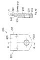
- the dressing tool 10 of Fig. 1 to 4 has a flat-cuboid body 12, which consists of metal, in particular of an alloyed tool steel. Also In this respect, reference is made formally to known materials for dressing tools.
- the dressing tool 10 is subdivided into a base portion 16 or base portion preferably having an opening 14 for mounting a tool holder, and an attachment piece 18 in which abrasive particles are fixed in the manner described below to form a grinding area by means of which dressing work is performed with the tool 10 can.
- the base portion 12 and extension 18 are, as mentioned, a purely formal distinction that is not intended to be limiting.
- this has in its upper portion referred to as an extension 18 on a slot to be designated by sections or legs 19, 21 of the extension piece 10 limited gap 20 which extends over the entire width of the plate-shaped body 12 and the base portionferneaude End face 22 of the endpiece 18 passes through.
- the end face 22 in this case has an obliquely extending boundary surface 24, 25 with respect to the longitudinal axis 30, as is usual with dressing plates or tiles.
- the gap 20 is bounded by inner walls 26, 28 of the legs 19, 21, which run parallel to each other, wherein the extending in the drawing right inner wall 28 preferably spans a plane in which the longitudinal axis 30 of the dressing tool 10 extends.
- - formed in the embodiment as grains - abrasive particles 32, 34 are introduced and connected by vacuum brazing with the boundary walls to be designated walls 26, 28, which thus form soldering areas.
- the natural diamond, synthetic diamond such as CVD, polycrystalline diamond (PCD), monocrystalline diamond, cubic boron nitride or hard metal abrasive particles 32, 34 which should preferably have a mean diameter between 100 microns and 2500 microns in a grain shape, to simple Positioning and aligning in the desired geometry to each other, is provided according to the invention that the abrasive particles 32, 34 are fixed in a support 36 prior to introduction into the gap 20, in the Embodiment is a grid, wherein the mesh size can be 100 microns to 2500 microns in the above dimensions of the abrasive particles 32, 34.
- the grid 36 which can also be referred to as wire mesh, should be dimensionally stable, so that bending both when introducing and fixing the abrasive particles 32, 34 and when inserting into the gap 20 of the attachment piece 18 is avoided.
- the grid 36 z. B. are coated with a solder paste, which is used for vacuum brazing, which consists of a brazing metal components and an active metal components.
- the metal component should be selected from the group consisting of copper, silver, tin, silicon and iron and / or the active metal component from the group titanium, titanium hydride, chromium, zirconium.
- the solder paste contains an organic binder, especially water-based.
- the abrasive particles 32, 34 are then pressed into the paste present in the openings 38, 40 in order to fix them.
- the introduction into the openings 38, 40 can be done manually or automatically.
- solder material can also be used a different curable adhesive material, such as adhesive material.
- a different curable adhesive material such as adhesive material.
- the abrasive particles 32 after fixing the abrasive particles 32, they are covered with a solder material suitable for vacuum brazing to the extent necessary to perform brazing after introducing the carrier 36 into the gap 20 in a vacuum or a non-oxidizing atmosphere at reduced pressure, whereby the abrasive particles 32, 34 are connected to both the carrier 36 and with the boundary walls 26, 28, ie the soldering area.
- the curable adhesive material and the solder paste can be dried. However, this can also be done after positioning in the gap 20 and in the vacuum chamber in which the brazing is performed.
- abrasive particles 32, 34 basically protrude laterally beyond the carrier or grid 36.
- a further dressing tool 100 is shown purely in principle, which may correspond to previously known from the outer geometry dressing plates.
- the dressing tool 100 also includes a body 112 that is formally divided into a base portion 116 and an extension 118 that forms a grinding area for dressing tools after abrasive particles have been bonded to a soldering area of the nosepiece 118.
- the hub 118 does not have a gap, but a flat, free soldering region 120 that is an outer surface of the hub 118 and that can extend in the longitudinal axis 130 of the dressing tool 100, as shown in the drawing.
- the outer area forming the soldering area 120 extends in the embodiments of FIGS Fig. 6 to 8 set back to the right in the drawing outer surface of the base member 116.
- the opposite outer surfaces are flush with each other, as the sectional view in accordance with Fig. 7 clarified.
- a frame 136 located in which according to the teaching of the present invention, a carrier is arranged with fixed in this abrasive particles, then to be connected by particular vacuum brazing with the endpiece 118.
- the carrier can according to the Fig. 3 a grid or sieve with in particular square openings.
- a commercially available wire mesh or an expanded metal may also be used, with the openings forming receptacles for the abrasive particles.
- a curable adhesive is first applied to the support, which may preferably be the paste-form solder material used to bond the abrasive particles to the hub 118. After fixing the abrasive particles in the carrier, this is placed on the solder surface 120, to then perform the brazing in a vacuum. Beforehand, the adhesive is dried.
- the side edges of the inner surface extending parallel to the longitudinal axis 130 can each have a web-like projection 122, as can the detail representation according to FIG Fig. 8 should clarify.
- the webs 122 thus serve as a guide for the soldering area 120 auf complexityden carrier with fixed in this abrasive particles.
- the base portion 116 may include a through hole 114 for connecting the dressing tool 100 to a bracket.
- soldering region 220 in its longitudinal edges 222, 224 has a frame-like web to a according to the teaching of the invention a to be guided on the soldering region 120 and can be placed on this carrier and thus ensure a positionally accurate positioning.
- a support 36 with abrasive grains 32, 34 shown which have a grain geometry, so according to the teaching of the invention also given the opportunity to equip a dressing tool 300 with needle-shaped abrasive grains 332, 334, which are also arranged in a carrier 336 and fixed.
- the carrier 336 can be a plate which, in accordance with the desired orientation of the needle-shaped abrasive grains 332, 334, has unspecified depressions into which the abrasive particles 332, 334 can be inserted and fixed. If necessary, the recesses can be designed as passage openings.
- the length of the needles may be between 2 mm and 6 mm.
- the shape of the needles is rod-like, with the width of each side being between 0.2 mm and 1.4 mm.
- the needles have a square cross-section, such as. 0.6 x 0.6 x 3 mm, 0.8 x 0.8 x 6 mm or 1.2 x 1.2 x 12 mm.
- the dressing tool 300 has a structure similar to that of the Fig. 1 to 5 corresponds, so that reference is made to the relevant explanations.
- the dressing tool 300 has a flat cuboid body made of metal, in particular steel such as alloyed tool steel.
- the body 316 has an extension 318 with a gap 320 bounded by walls 326, 328. Notwithstanding the embodiment of Fig.
- the carrier 336 with the needle-shaped abrasive particles 332, 334 inserted into the gap 320 such that the abrasive particles 332, 334 contact the wall 328.
- the dressing tool 300 is illustrated graphically. Before the dressing tool 300 is used, the end face 322 with the inclined sections 324, 326 is then machined so that the outermost abrasive particles 332 extend flush with the end face 322 or its section 324 in order to be able to dress or turn off.
Landscapes
- Engineering & Computer Science (AREA)
- Mechanical Engineering (AREA)
- Polishing Bodies And Polishing Tools (AREA)
Applications Claiming Priority (1)
| Application Number | Priority Date | Filing Date | Title |
|---|---|---|---|
| DE102013107266.6A DE102013107266A1 (de) | 2013-07-09 | 2013-07-09 | Abrichtwerkzeug und Verfahren zum Herstellen eines solchen |
Publications (2)
| Publication Number | Publication Date |
|---|---|
| EP2853347A2 true EP2853347A2 (fr) | 2015-04-01 |
| EP2853347A3 EP2853347A3 (fr) | 2015-11-04 |
Family
ID=51212679
Family Applications (1)
| Application Number | Title | Priority Date | Filing Date |
|---|---|---|---|
| EP14176364.9A Withdrawn EP2853347A3 (fr) | 2013-07-09 | 2014-07-09 | Outil d'ajustement et son procédé de fabrication |
Country Status (2)
| Country | Link |
|---|---|
| EP (1) | EP2853347A3 (fr) |
| DE (1) | DE102013107266A1 (fr) |
Cited By (4)
| Publication number | Priority date | Publication date | Assignee | Title |
|---|---|---|---|---|
| WO2016177895A1 (fr) | 2015-05-06 | 2016-11-10 | Jakob Lach Gmbh & Co. Kg | Procédé de fabrication d'un outil ou d'une pièce |
| DE102015107077A1 (de) | 2015-05-06 | 2016-11-10 | Jakob Lach Gmbh & Co. Kg | Verfahren zur Herstellung eines Werkzeugs |
| DE102015115406A1 (de) | 2015-09-11 | 2017-03-16 | Jakob Lach Gmbh & Co. Kg | Verfahren zur Herstellung eines Bauteils |
| CN112259317A (zh) * | 2020-09-29 | 2021-01-22 | 核工业西南物理研究院 | 一种热核聚变堆超导线圈热屏蔽部件及其制备方法 |
Families Citing this family (1)
| Publication number | Priority date | Publication date | Assignee | Title |
|---|---|---|---|---|
| DE102017214279A1 (de) * | 2017-08-16 | 2019-02-21 | ROT GmbH | Abrichtwerkzeug mit Hartstoffelementen in Spuren |
Citations (5)
| Publication number | Priority date | Publication date | Assignee | Title |
|---|---|---|---|---|
| DE1093692B (de) | 1955-04-21 | 1960-11-24 | Woldemar Ladinsky | Schneidwerkzeug, insbesondere zum Abrichten von Schleifscheiben |
| DE69028455T2 (de) | 1989-01-30 | 1997-03-20 | Peter T. Atlanta Ga. Dekok | Schleifwerkzeug und verfahren zur herstellung |
| DE69914766T2 (de) | 1998-07-31 | 2004-11-25 | Saint-Gobain Abrasives, Inc., Worcester | Drehende abrichtrolle mit aufgelöteter diamantschicht |
| DE69833314T2 (de) | 1997-04-04 | 2006-10-19 | Sung, Chien-Min | Gelötete diamantwerkzeuge durch infiltration |
| DE112005001119B4 (de) | 2004-05-18 | 2012-02-23 | Saint-Gobain Abrasives, Inc. | Abrichtklinge zum Bearbeiten von Schleifwerkzeugen und Verfahren zum Anfertigen einer Abrichtklinge |
Family Cites Families (5)
| Publication number | Priority date | Publication date | Assignee | Title |
|---|---|---|---|---|
| BE794337A (fr) * | 1972-01-19 | 1973-05-16 | Cirell Rudy J | Outil pour decrasser et dresser des meules et des matieres abrasives analogues |
| DE2210267C3 (de) * | 1972-03-03 | 1974-08-29 | Ernst Winter & Sohn, 2000 Hamburg | Diamantwerkzeug, - sogea Diamantfliese - insbesondere zum Abrichten von Schleifscheiben, mit einem etwa plattenförmigen Diamantträger und in ihm in Schichten angeordneten Diamanten |
| US5049165B1 (en) * | 1989-01-30 | 1995-09-26 | Ultimate Abrasive Syst Inc | Composite material |
| DE102010000921A1 (de) * | 2009-01-15 | 2010-07-29 | Bernd Kuntz | Abrichtwerkzeug und Verfahren zu dessen Herstellung |
| WO2012006281A2 (fr) * | 2010-07-06 | 2012-01-12 | Baker Hughes Incorporated | Procédés de formation d'inserts et d'outils de forage de terre |
-
2013
- 2013-07-09 DE DE102013107266.6A patent/DE102013107266A1/de not_active Withdrawn
-
2014
- 2014-07-09 EP EP14176364.9A patent/EP2853347A3/fr not_active Withdrawn
Patent Citations (6)
| Publication number | Priority date | Publication date | Assignee | Title |
|---|---|---|---|---|
| DE1093692B (de) | 1955-04-21 | 1960-11-24 | Woldemar Ladinsky | Schneidwerkzeug, insbesondere zum Abrichten von Schleifscheiben |
| DE69028455T2 (de) | 1989-01-30 | 1997-03-20 | Peter T. Atlanta Ga. Dekok | Schleifwerkzeug und verfahren zur herstellung |
| DE69034066T2 (de) | 1989-01-30 | 2004-03-25 | Ultimate Abrasive Systems L.L.C. | Schleifmittel und Verfahren zu dessen Herstellung |
| DE69833314T2 (de) | 1997-04-04 | 2006-10-19 | Sung, Chien-Min | Gelötete diamantwerkzeuge durch infiltration |
| DE69914766T2 (de) | 1998-07-31 | 2004-11-25 | Saint-Gobain Abrasives, Inc., Worcester | Drehende abrichtrolle mit aufgelöteter diamantschicht |
| DE112005001119B4 (de) | 2004-05-18 | 2012-02-23 | Saint-Gobain Abrasives, Inc. | Abrichtklinge zum Bearbeiten von Schleifwerkzeugen und Verfahren zum Anfertigen einer Abrichtklinge |
Cited By (4)
| Publication number | Priority date | Publication date | Assignee | Title |
|---|---|---|---|---|
| WO2016177895A1 (fr) | 2015-05-06 | 2016-11-10 | Jakob Lach Gmbh & Co. Kg | Procédé de fabrication d'un outil ou d'une pièce |
| DE102015107077A1 (de) | 2015-05-06 | 2016-11-10 | Jakob Lach Gmbh & Co. Kg | Verfahren zur Herstellung eines Werkzeugs |
| DE102015115406A1 (de) | 2015-09-11 | 2017-03-16 | Jakob Lach Gmbh & Co. Kg | Verfahren zur Herstellung eines Bauteils |
| CN112259317A (zh) * | 2020-09-29 | 2021-01-22 | 核工业西南物理研究院 | 一种热核聚变堆超导线圈热屏蔽部件及其制备方法 |
Also Published As
| Publication number | Publication date |
|---|---|
| DE102013107266A1 (de) | 2015-01-15 |
| EP2853347A3 (fr) | 2015-11-04 |
Similar Documents
| Publication | Publication Date | Title |
|---|---|---|
| DE112005001119B4 (de) | Abrichtklinge zum Bearbeiten von Schleifwerkzeugen und Verfahren zum Anfertigen einer Abrichtklinge | |
| AT515258B1 (de) | Verfahren zur Herstellung von Schleifkörpern | |
| DE3486140T2 (de) | Verfahren zur herstellung eines bohrers fuer leiterplatten. | |
| EP2853347A2 (fr) | Outil d'ajustement et son procédé de fabrication | |
| DE2808455A1 (de) | Schneid- und schleifwerkzeug | |
| EP3385014B1 (fr) | Procédé de fabrication d'un outil de perçage par usinage par enlèvement de copeaux des pièces à usiner ainsi qu'outil de perçage | |
| DE102012202976A1 (de) | Fräser für die Hartzerspanung | |
| WO2020127623A1 (fr) | Procédé pour fabriquer un segment d'usinage pour l'usinage à sec de matériaux de béton | |
| EP3674025A1 (fr) | Segment de traitement pour le traitement à sec de matériaux de béton | |
| DE102012203088A1 (de) | Bohrkrone | |
| EP2859975A1 (fr) | Outil de coupe rotatif présentant des bords coupants s'étendant en forme de vis ainsi que procédé de fabrication de celui-ci | |
| EP1839792A1 (fr) | Lame de scie dotée d'un corps de base et de dents ayant une lame de coupe | |
| DE4338077C2 (de) | Honelement | |
| DE1758823B2 (de) | Kernbohrer | |
| DE112008000082B4 (de) | Schneidplatte und Verfahren zur Herstellung einer Schneidplatte | |
| DE102018122340B4 (de) | Werkzeugträger mit kerbe, schneideinsatz und verfahren zu seiner herstellung | |
| EP3993938B1 (fr) | Outil d'usinage par enlèvement de copeaux à dents asymétriques munies de particules de coupe | |
| DE8108082U1 (de) | Abrichtwerkzeug | |
| EP3661674A1 (fr) | Procédé pour la fabrication d'un segment opératoire pour un outil d'usinage abrasif | |
| DE622823C (de) | Verfahren zur Herstellung von Schneidwerkzeugen, bei denen harte Schneidteilchen in eine tragende Grundmassen aus sinterungsfaehigen Stoffen eingebettet sind | |
| DE202005000994U1 (de) | Spanabhebendes Werkzeug | |
| EP1749630A1 (fr) | Outil de coupe ou de séparation | |
| DE10049605A1 (de) | Werkzeug für Steinbearbeitung | |
| WO2018050271A2 (fr) | Corps de coupe d'outil, outil et procédé de fabrication dudit outil | |
| DE8520749U1 (de) | Diamantwerkzeug zum Abrichten und Profilieren von Schleifscheiben |
Legal Events
| Date | Code | Title | Description |
|---|---|---|---|
| PUAI | Public reference made under article 153(3) epc to a published international application that has entered the european phase |
Free format text: ORIGINAL CODE: 0009012 |
|
| 17P | Request for examination filed |
Effective date: 20140709 |
|
| AK | Designated contracting states |
Kind code of ref document: A2 Designated state(s): AL AT BE BG CH CY CZ DE DK EE ES FI FR GB GR HR HU IE IS IT LI LT LU LV MC MK MT NL NO PL PT RO RS SE SI SK SM TR |
|
| AX | Request for extension of the european patent |
Extension state: BA ME |
|
| PUAL | Search report despatched |
Free format text: ORIGINAL CODE: 0009013 |
|
| AK | Designated contracting states |
Kind code of ref document: A3 Designated state(s): AL AT BE BG CH CY CZ DE DK EE ES FI FR GB GR HR HU IE IS IT LI LT LU LV MC MK MT NL NO PL PT RO RS SE SI SK SM TR |
|
| AX | Request for extension of the european patent |
Extension state: BA ME |
|
| RIC1 | Information provided on ipc code assigned before grant |
Ipc: B24B 53/12 20060101AFI20151001BHEP |
|
| STAA | Information on the status of an ep patent application or granted ep patent |
Free format text: STATUS: THE APPLICATION IS DEEMED TO BE WITHDRAWN |
|
| 18D | Application deemed to be withdrawn |
Effective date: 20160505 |