EP2853377A2 - Système de changement pour machine d'enduction ainsi que procédé - Google Patents
Système de changement pour machine d'enduction ainsi que procédé Download PDFInfo
- Publication number
- EP2853377A2 EP2853377A2 EP14186162.5A EP14186162A EP2853377A2 EP 2853377 A2 EP2853377 A2 EP 2853377A2 EP 14186162 A EP14186162 A EP 14186162A EP 2853377 A2 EP2853377 A2 EP 2853377A2
- Authority
- EP
- European Patent Office
- Prior art keywords
- receptacle
- coating material
- workpiece
- unit
- exchange system
- Prior art date
- Legal status (The legal status is an assumption and is not a legal conclusion. Google has not performed a legal analysis and makes no representation as to the accuracy of the status listed.)
- Granted
Links
- 239000011248 coating agent Substances 0.000 title claims abstract description 76
- 238000000576 coating method Methods 0.000 title claims abstract description 76
- 238000000034 method Methods 0.000 title claims abstract description 14
- 239000000463 material Substances 0.000 claims abstract description 126
- 238000010030 laminating Methods 0.000 claims abstract description 58
- 238000004806 packaging method and process Methods 0.000 claims description 29
- 239000000853 adhesive Substances 0.000 claims description 27
- 230000001070 adhesive effect Effects 0.000 claims description 27
- 238000003860 storage Methods 0.000 claims description 15
- 230000008569 process Effects 0.000 claims description 5
- 238000012545 processing Methods 0.000 claims description 5
- 238000010438 heat treatment Methods 0.000 claims description 4
- 230000008859 change Effects 0.000 description 13
- 230000007246 mechanism Effects 0.000 description 11
- 238000012986 modification Methods 0.000 description 7
- 230000004048 modification Effects 0.000 description 7
- 230000001360 synchronised effect Effects 0.000 description 5
- 230000001133 acceleration Effects 0.000 description 3
- 238000012423 maintenance Methods 0.000 description 2
- 239000002023 wood Substances 0.000 description 2
- 239000002313 adhesive film Substances 0.000 description 1
- 239000012790 adhesive layer Substances 0.000 description 1
- 238000013459 approach Methods 0.000 description 1
- 238000005452 bending Methods 0.000 description 1
- 230000005540 biological transmission Effects 0.000 description 1
- 238000004140 cleaning Methods 0.000 description 1
- 238000005520 cutting process Methods 0.000 description 1
- 238000013016 damping Methods 0.000 description 1
- 238000005034 decoration Methods 0.000 description 1
- 230000001419 dependent effect Effects 0.000 description 1
- 238000013461 design Methods 0.000 description 1
- 238000011161 development Methods 0.000 description 1
- 230000018109 developmental process Effects 0.000 description 1
- 238000003475 lamination Methods 0.000 description 1
- 238000002844 melting Methods 0.000 description 1
- 230000008018 melting Effects 0.000 description 1
- 230000000704 physical effect Effects 0.000 description 1
- 238000003825 pressing Methods 0.000 description 1
- 230000009467 reduction Effects 0.000 description 1
- 230000003068 static effect Effects 0.000 description 1
- 239000000126 substance Substances 0.000 description 1
- 238000012546 transfer Methods 0.000 description 1
- 239000002699 waste material Substances 0.000 description 1
Images


Classifications
-
- B—PERFORMING OPERATIONS; TRANSPORTING
- B29—WORKING OF PLASTICS; WORKING OF SUBSTANCES IN A PLASTIC STATE IN GENERAL
- B29C—SHAPING OR JOINING OF PLASTICS; SHAPING OF MATERIAL IN A PLASTIC STATE, NOT OTHERWISE PROVIDED FOR; AFTER-TREATMENT OF THE SHAPED PRODUCTS, e.g. REPAIRING
- B29C63/00—Lining or sheathing, i.e. applying preformed layers or sheathings of plastics; Apparatus therefor
- B29C63/0004—Component parts, details or accessories; Auxiliary operations
-
- B—PERFORMING OPERATIONS; TRANSPORTING
- B32—LAYERED PRODUCTS
- B32B—LAYERED PRODUCTS, i.e. PRODUCTS BUILT-UP OF STRATA OF FLAT OR NON-FLAT, e.g. CELLULAR OR HONEYCOMB, FORM
- B32B37/00—Methods or apparatus for laminating, e.g. by curing or by ultrasonic bonding
- B32B37/14—Methods or apparatus for laminating, e.g. by curing or by ultrasonic bonding characterised by the properties of the layers
- B32B37/16—Methods or apparatus for laminating, e.g. by curing or by ultrasonic bonding characterised by the properties of the layers with all layers existing as coherent layers before laminating
- B32B37/22—Methods or apparatus for laminating, e.g. by curing or by ultrasonic bonding characterised by the properties of the layers with all layers existing as coherent layers before laminating involving the assembly of both discrete and continuous layers
-
- B—PERFORMING OPERATIONS; TRANSPORTING
- B29—WORKING OF PLASTICS; WORKING OF SUBSTANCES IN A PLASTIC STATE IN GENERAL
- B29C—SHAPING OR JOINING OF PLASTICS; SHAPING OF MATERIAL IN A PLASTIC STATE, NOT OTHERWISE PROVIDED FOR; AFTER-TREATMENT OF THE SHAPED PRODUCTS, e.g. REPAIRING
- B29C63/00—Lining or sheathing, i.e. applying preformed layers or sheathings of plastics; Apparatus therefor
- B29C63/02—Lining or sheathing, i.e. applying preformed layers or sheathings of plastics; Apparatus therefor using sheet or web-like material
Definitions
- the present invention relates to a changing system for a coating machine, with which a coating material, in particular a laminating material, for application to a workpiece is provided. Furthermore, the present invention relates to a method for providing a coating material, in particular laminating material.
- claim 1 provides a solution for this purpose. Further exemplary embodiments are set forth in the dependent claims. Furthermore, the present invention relates to a method according to claim 14.
- the change system comprises a support table for receiving a workpiece. Furthermore, at least one receptacle of a coating material, in particular a laminating material, is provided.
- the coating material is usually in a packaging unit, in particular a disposable packaging, which is dimensioned such that it can be received and held in the receptacle.
- the receptacle comprises an opening and a guide element for guiding and attaching the coating material to a workpiece.
- the guide element is aligned on the receptacle such that, in the state in which the coating material is applied to a workpiece, it faces the workpiece.
- the receptacle is movable to be moved from a transfer position, in which the recording is loaded with the coating material, in an operating position in which the coating material is applied to a workpiece.
- the present invention thus provides a device with which a large variety of coating materials can be provided in an application-specific manner, and thus a greater variety of variants can be ensured. At the same time, because of the specific provision, waste can be avoided. This leads to a greater flexibility of the process flows. Set-up times and cleaning and maintenance times are shortened, and storage is simplified or reduced. Also, follow-up processes can be easily matched with the functionalities of the device.
- the guide element of the receptacle comprises a heating element.
- the coating material can be heated in the region of the guide element, and possibly made flexible.
- the coating material is easier to apply to a workpiece.
- the guide element can either be bead-shaped, or comprise a roller.
- the bead-shaped configuration which represents a certain curvature of the guide element, for example in the form of a clothoid, can be realized relatively inexpensively, and requires little maintenance.
- the guide element has a small coefficient of static friction against laminating material.
- a role as a guide element can be used when sensitive coating materials are processed.
- a soft, rubberized roll is used, which has, for example, damping or balancing properties.
- the changing system comprises a rotatable exchange unit to which the receptacle is received.
- the receptacle can be rotated from a position in which it is charged with the coating material to an operating position in which the coating material is applied to a workpiece.
- the exchange unit is further movable in at least one translational direction.
- the receptacle can be moved to a position in which the coating material is received.
- This can For example, be a storage unit in which a variety of coating materials is kept.
- the receptacle is movable in at least one translational direction. In this way, the receptacle can be moved between a position in which it is charged with the coating material and an operating position.
- the receptacle is mounted by means of an elastic element.
- the elastic element is thus between the receptacle and the exchange unit.
- the elastic element is located between the receptacle and a moving unit, which moves the receptacle in the translational direction.
- the change system can comprise an adhesive application unit, in particular a nozzle and a counterpart, which adhesive application unit for an adhesive application to a coating material is preferably positionable relative to a receptacle.
- an adhesive application unit in particular a nozzle and a counterpart, which adhesive application unit for an adhesive application to a coating material is preferably positionable relative to a receptacle.
- the adhesive application unit can also supply a tape to which an adhesive is applied, which in the region of the adhesive application unit, for example by means of a roller on the Coating material is transferred.
- the adhesive itself may be ribbon-shaped.
- the adhesive application device is set up to change the chemical and / or physical properties of the adhesive (for example the melting point), the adhesive thickness and / or the amount of adhesive. In this way, the adhesive itself can be adapted to a batch size 1 processing.
- the coating material is withdrawn from the receptacle due to the pressure between the guide element and the workpiece.
- This variant is used in particular in the case of sensitive coating materials, or in embodiments where additional processing steps are carried out on a workpiece before applying the coating material, such as the application of an adhesive layer.
- the changing system comprises a control unit which synchronizes a movement of the receptacle with a movement of a workpiece in a section, in which section the coating material comes into contact with the workpiece. In this way, a coating material can be placed very gently on a workpiece.
- the change system can comprise a storage unit in which packaging units with coating materials are accommodated.
- a storage unit may be, for example, a shelving system.
- the receptacle may have a receiving unit with which an information unit, in particular an RFID tag, of the coating material can be read out. In this way, it is possible to verify whether the "correct" coating material that is to be applied to a specific workpiece in accordance with a control command has been recorded in a specific recording.
- an information unit in particular an RFID tag
- the support table for receiving a workpiece preferably comprises rollers, over which rollers the workpiece is moved.
- belts may be provided.
- individual rollers or all rollers can be driven, or on the support table, a conveying mechanism is provided which moves the workpiece via freely rotatable rollers.
- the exchange system comprises a plurality of receptacles. In this way, a receptacle for applying a coating material on a workpiece can be used, while another recording is fed with a new coating material.
- the method according to the invention comprises the steps of feeding a receptacle with a coating material, in particular a packaging unit with a laminating material, moving the receptacle from a receiving position in which the receptacle is charged with the coating material in an operating position in which the coating material is applied to a workpiece, applying the coating material on a workpiece.
- the process can be preceded by the following steps: creation of a decorative image of the coating material, transmission of the decorative image via an online connection, Processing the data and creating a coating material, providing the decorating material provided with the decorative image.
- the steps mentioned can be carried out both by the operator of a system for carrying out the method (producer of the workpieces) and by a supplier.
- information storage units can be provided on the first area of the laminating material (decal sheet), or on the packaging unit of the coating material, which is designed in particular as a disposable packaging.
- an order of a specific coating material can be uniquely assigned, and it is possible to provide it individually for a particular workpiece.
- the edge material of a workpiece can also be provided in a corresponding manner. Accordingly, it is possible to produce individual workpieces with the same (or coordinated) laminating and edge material in batch size 1 cost.
- edge material can be manufactured to match this or a narrow surface of a workpiece can be printed accordingly, or vice versa.
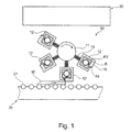
- a change mechanism 10 for example, a support table 20 and a bearing unit 30 are shown schematically.
- the support table 20 in the present embodiment includes a plurality of rollers 21 through which a workpiece W can slide.
- some of the rollers 21 may be driven to rotate the workpiece W as indicated by the arrow in FIG Fig. 1 to move in the direction indicated.
- the rollers 21 may be freely movable, and the workpiece W is moved along the support table 20 via a mechanism, not shown in detail, for example one or more belts.
- the change mechanism 10 includes an exchange unit 11 located in the in Fig. 1 illustrated embodiment can rotate clockwise. Further, the exchange unit 11 can be moved in a vertical direction.
- a plurality of receptacles 12 are mounted, which are formed substantially the same. Accordingly, only one of these shots 12 will be explained in more detail below.
- the number of receptacles 12 is not limited: one, two or more receptacles 12 may be provided.
- the receptacle 12 is connected via an elastic element 13 with the exchange unit 11.
- the elasticity is provided here in a substantially radial direction between the receptacle 12 and the exchange unit 11.
- the task of the elastic element 13 is, inter alia, to compensate for the tolerances occurring (primarily workpiece tolerances) by the tactile-resilient mounting of the receptacles 12.
- the receptacle 12 deviates during lamination by the amount of the workpiece surface, which is above the nominal size of the workpiece thickness. After a few millimeters, in which the Kaschiermaterial K was pressed with the set contact pressure on the workpiece surface, the guide element can be lifted.
- position control algorithms can also perform a positioning of the receptacle relative to the workpiece surface.
- the housing-shaped receptacle 12 comprises an opening 14 through which, as described in more detail below, a laminating material K can pass.
- a guide element 15 is provided which guides the laminating material K and causes the laminating material K to be pressed against a workpiece W.
- the guide member 15 is formed bead-shaped.
- a heating device may be provided in the region of the guide element 15 in order to facilitate bending of the laminating material K or to prevent it from breaking.
- a heating device can be used for certain laminating materials K, while other Kaschiermaterialen K sensitive to such heat input. Accordingly, a heating device according to this variant is variably switchable. In an additional modification, the temperature can be controlled in order to match this with the laminating material K received in the receptacle 12.
- a packaging unit KV for a laminating material K is received. This is provided by the manufacturer of the laminating material K, and takes this up.
- the packaging unit KV is usually a disposable packaging. The liner is received therein in a rolled condition, usually without providing an additional pivot.
- a not shown in detail number of packaging units KV is kept. If required, these can be picked up by a receptacle 12 and provided for coating a workpiece W.
- a packaging unit KV with a corresponding laminating material K is inserted manually or controlled by a mechanism of the storage unit 30 into a receptacle 12. This happens in the illustrated Embodiment in a horizontal direction.
- the exchange unit 11 of the exchange mechanism 10 performs a rotation, and brings the receptacle 12 with the packaging unit KV in a vertically downward orientation, so that between the receptacle 12 and the rollers 21 of the support table 20 results in a gap substantially the thickness of a workpiece W and coating material K or slightly less than a total of these corresponds.
- a workpiece W is moved in the conveying direction through this gap (indicated by the arrow in FIG. 1 indicated from left to right), so that the Kaschiermaterial K deducted due to the adhesion between the Kaschiermaterial K and the workpiece W and by the applied by means of the guide member 15 pressure from the packaging unit KV or the receptacle 12 and applied to the workpiece W.
- the receptacle 12 can be synchronized with respect to the speed of the workpiece front edge.
- a controlled placement of the laminating material K occurs, followed by a positive or negative acceleration, that is, an increase or decrease in the speed of the recording. Accordingly, there is a relative movement between the recording and the workpiece.
- the gentle touchdown is particularly advantageous for sensitive, so for example thin, laminating materials.
- the change mechanism is actuated, and the exchange unit 11 continues to rotate the emptied receptacle 12. Now the next workpiece can be coated by a laminating material K of the next receptacle 12.
- the feeding of the individual receptacles 12 with the packaging units KV can take place during a laminating process of a workpiece, or an overlay with a magazine can be provided.
- the laminating material K is provided ready-made in a packaging unit KV, that is, the width and length of the laminating material K substantially correspond to the dimensions of a workpiece W to be coated.
- a plurality of sections of the laminating material K can be accommodated in a packaging unit KV.
- the side of the workpiece W facing the receptacle 12, on which the laminating material K is to be applied is provided with an adhesive.
- an adhesive it is also possible to apply an adhesive to the laminating material K before it is pressed onto the workpiece W. This possibility is explained in more detail in the context of the third embodiment described below, but can also be found in the in Fig. 1 shown embodiment are used.
- Fig. 2 a modification of the first embodiment is shown schematically, which differs substantially by the embodiment of the receptacle 12 'of the first embodiment.
- the change mechanism 10 has a guide element 15 ', which can be adjusted at least in a horizontal direction, and possibly also in a vertical direction, or arcuately.
- the guide element 15 ' can be moved together with one of the receptacles 12', with which a coating material is to be applied to a workpiece, so that the guide element 15 'approaches or even touches the guide element 15' when the coating material is applied to the receptacle 12 ' , In this state, the guide element 15 'takes over a corresponding task as the guide element 15 of the first embodiment, namely to guide the coating material and possibly press on a workpiece.
- Fig. 2 illustrated modification of the first embodiment thus has a guide element for all recordings 12 ', whereby the weight of the receptacle (s) is reduced. Furthermore, the recordings have a simpler structure.
- the change mechanism can not only do that in Fig. 2 shown guide element 15 'have. Rather, different guide elements can be individually deliverable, so that the most suitable for a particular coating material guide element can be delivered.
- the guide element 15 'ein grillbar in a holder is. In this way, different guide elements can be kept, which are then used as needed.
- FIG. 3 A second embodiment of the present invention is shown schematically.
- the support table 20 is similar to that of in Fig. 1 formed embodiment illustrated.
- the receptacle 12a for receiving a packaging unit KV substantially corresponds to the receptacle 12 according to the first embodiment.
- the exchange mechanism 10a of the second embodiment does not include an exchangeable unit 11, but the receptacle 12a is horizontally and vertically movable along translational directions.
- the second embodiment also preferably comprises a plurality of receptacles, are in Fig. 3 only multiple positions of a particular shot shown.
- the receptacle 12a is supported via an elastic member 13a whose configuration is similar to or similar to the elastic member 13a of the first embodiment.
- the attachment of the elastic element 13a to a moving part is not explicitly shown.
- a plurality of positions of the receptacle 12a are shown, which also reproduce the procedure for applying the Kaschiermaterial K on the workpiece W.
- the receptacle 12a is moved from the position 1, in which, for example, the packaging unit KV is changed into the receptacle 12, in the waiting position 2.
- the so-called acceleration phase 3 is started.
- the receptacle 12a to the speed of the workpiece leading edge synchronized.
- the laminating material K is placed over a guide element 15a arranged in the region of an opening 14a on the side of the workpiece W to be coated.
- a positive or negative occurs Acceleration of the recording in the direction of the position 5 or the position 2, depending on the design of lot size-related Kaschiermaterials K.
- the receptacle 12a then remains in the position 2 or 5.
- the next workpiece W can be coated with another laminating material K on the same receptacle 12a (for example position 2) or with another laminating material K from another receptacle 12a.
- the receptacle 12a is moved out of the working area (between the positions 2-5) into the area of the position 6, so that the next receptacle 12a can move over the position 1 into the waiting position 2.
- the second embodiment as the modification of the first embodiment may have a separate guide member from the recording.
- FIG. 4 A further embodiment of the present invention will be explained, which differs from that of the second embodiment substantially by the configuration of the receptacle 12b.
- the receptacle 12b is supported by an elastic member 13b similar or similar to that of the second embodiment, and accommodates a packaging unit KV with a liner K.
- an opening 14 b is provided, can pass through the laminating K from the interior of the receptacle 12 b to the outside.
- a roller pair 16b is provided, wherein one of the rollers 16b or both is driven. These rollers 16b ensure that the laminating material K is withdrawn controlled from the interior of the receptacle 12b.
- the receptacle 12b further comprises an arm 12b 'which extends downwards in the vertical direction, and at the distal end of which a roller 15b is received.
- This roller 15b performs a similar function as the guide element 15, 15a of the first and second embodiment.
- the apparatus further comprises an adhesive application unit 40, which in the present embodiment comprises a nozzle 41 and a counterpart 42. Between the nozzle 41 and the counterpart 42, the laminating material K is guided between the rollers 16b and the roller 15b.
- an adhesive application unit 40 which in the present embodiment comprises a nozzle 41 and a counterpart 42.
- the adhesive application unit 40 could be combined with the receptacle 12b. However, it is provided in the present embodiment that the adhesive application unit 40 is provided separately, and is brought to apply an adhesive in a corresponding position relative to the receptacle 12b.
- Fig. 4 is shown in position 1, a waiting position of the receptacle 12, in which the receptacle 12 b is kept.
- the receptacle 12 In position 2, the receptacle 12 is in a working position after the speed of the receptacle 12b has been synchronized with the movement of the leading edge of the workpiece W or - as in the first embodiment - a defined gap between the rollers 21 of the Support table 20 and the roller 15b of the receptacle 12b is formed.
- the adhesive is withdrawn in the form of an adhesive film from a roll, and is pressed by a pressing on the laminating material K.
- the adhesive applying unit 40 may be omitted in the case where an adhesive is applied to the workpiece as in the case of the first and second embodiments.
- the laminating material K is accommodated in a packaging unit KV.
- the packaging unit KV (or alternatively the laminating material K itself) is provided with an information storage unit, for example an RFID tag. On the information storage unit specific information regarding the Kaschiermaterials K are deposited. These data are stored by the manufacturer of the laminating material in the information storage unit.
- the packaging unit KV is subsequently delivered to the customer, and received in the storage unit 30.
- the packaging unit KV is loaded into a receptacle as described above, and the lining material K accommodated therein is used to coat a workpiece W.
- the information storage unit has specific information with respect to the laminating material K, and this information can be read out, a specific laminating material K can be provided for the coating of a workpiece W according to the customer's request.
- the customer can e.g. online with the manufacturer of Kaschiermaterials by means of a decor printer to create a specific decor image and the desired dimension of K Killiermaterials.
- the customer can make the main and narrow surfaces of a workpiece decorally equal by means of digital printing.
- the customer receives a clear decoration information regarding the laminating material, which is used for system control both on the laminating line and on the unit for coating the narrow sides of the workpiece.
- the information storage units can be located on the first area of the laminating material (decal sheet) or, as described above, on the packaging unit KV, which is designed in particular as a disposable packaging.
- the third embodiment may also have a guide element separate from the receptacle.
- the coating material was shown in a rolled state. Alternatively, however, this can also be accommodated in an arcuate manner in a receptacle.
Landscapes
- Engineering & Computer Science (AREA)
- Manufacturing & Machinery (AREA)
- Coating Apparatus (AREA)
- Application Of Or Painting With Fluid Materials (AREA)
Applications Claiming Priority (1)
| Application Number | Priority Date | Filing Date | Title |
|---|---|---|---|
| DE102013219270.3A DE102013219270A1 (de) | 2013-09-25 | 2013-09-25 | Wechselsystem für Beschichtungsmaschine sowie Verfahren |
Publications (3)
| Publication Number | Publication Date |
|---|---|
| EP2853377A2 true EP2853377A2 (fr) | 2015-04-01 |
| EP2853377A3 EP2853377A3 (fr) | 2015-07-29 |
| EP2853377B1 EP2853377B1 (fr) | 2017-05-31 |
Family
ID=51661868
Family Applications (1)
| Application Number | Title | Priority Date | Filing Date |
|---|---|---|---|
| EP14186162.5A Not-in-force EP2853377B1 (fr) | 2013-09-25 | 2014-09-24 | Système de changement pour machine d'enduction ainsi que procédé |
Country Status (3)
| Country | Link |
|---|---|
| EP (1) | EP2853377B1 (fr) |
| DE (1) | DE102013219270A1 (fr) |
| ES (1) | ES2635282T3 (fr) |
Cited By (1)
| Publication number | Priority date | Publication date | Assignee | Title |
|---|---|---|---|---|
| CN113619097A (zh) * | 2021-10-12 | 2021-11-09 | 潍坊富群新材料有限公司 | 一种防水卷材边膜覆膜装置 |
Families Citing this family (1)
| Publication number | Priority date | Publication date | Assignee | Title |
|---|---|---|---|---|
| DE102019113066A1 (de) * | 2019-05-17 | 2020-11-19 | Homag Gmbh | Verfahren und Appliziereinrichtung zum Applizieren eines bandförmigen Haftmittels sowie Beschichtungseinrichtung zum Beschichten plattenförmiger Werkstücke |
Family Cites Families (5)
| Publication number | Priority date | Publication date | Assignee | Title |
|---|---|---|---|---|
| ITUD20030027A1 (it) * | 2003-02-05 | 2004-08-06 | G M P Spa | Apparecchiatura per la sostituzione di una bobina di alimentazione di una pellicola di rivestimento, per la stesura e per il taglio della pellicola, e relativo metodo. |
| EP1813561B1 (fr) * | 2006-01-27 | 2011-08-17 | Veka AG | Procédé destiné au revêtement de surfaces de profilés dotés de bandes de feuilles de revêtement et son dispositif |
| DE102009015476B4 (de) * | 2009-03-28 | 2012-11-08 | Frimo Group Gmbh | Verfahren und Vorrichtung zur Zuführung gleicher oder verschiedener Folienbänder |
| DE202009019008U1 (de) * | 2009-04-22 | 2015-05-27 | Homag Holzbearbeitungssysteme Gmbh | Vorrichtung zum Beschichten von Werkstücken |
| DE102009021676A1 (de) * | 2009-05-18 | 2010-11-25 | Homag Holzbearbeitungssysteme Ag | Zufuhrvorrichtung |
-
2013
- 2013-09-25 DE DE102013219270.3A patent/DE102013219270A1/de not_active Withdrawn
-
2014
- 2014-09-24 ES ES14186162.5T patent/ES2635282T3/es active Active
- 2014-09-24 EP EP14186162.5A patent/EP2853377B1/fr not_active Not-in-force
Non-Patent Citations (1)
| Title |
|---|
| None |
Cited By (1)
| Publication number | Priority date | Publication date | Assignee | Title |
|---|---|---|---|---|
| CN113619097A (zh) * | 2021-10-12 | 2021-11-09 | 潍坊富群新材料有限公司 | 一种防水卷材边膜覆膜装置 |
Also Published As
| Publication number | Publication date |
|---|---|
| EP2853377B1 (fr) | 2017-05-31 |
| EP2853377A3 (fr) | 2015-07-29 |
| ES2635282T3 (es) | 2017-10-03 |
| DE102013219270A1 (de) | 2015-04-09 |
Similar Documents
| Publication | Publication Date | Title |
|---|---|---|
| DE19925087C2 (de) | Vorrichtung zum blasen- und faltenfreien Beschichten von optischen oder elektronischen Bauteilen mit einseitig klebender Schutzfolie | |
| EP2508353A2 (fr) | Machine destinée à la fabrication de livres, notamment livres photo et/ou livres illustrés | |
| EP3212550A1 (fr) | Procédé et dispositif de manipulation d'un matériau plat et/ou en feuille enroulé sur des rouleaux | |
| EP2976209B1 (fr) | Dispositif d'estampage de films | |
| DE102015213358A1 (de) | Zuführeinrichtung für Beschichtungsmaterial | |
| DE2936989A1 (de) | Verfahren und vorrichtung zum oeffnen eines zylindrischen folienschlauches sowie zu dessen ueberstuelpen ueber einen gegenstand | |
| DE3149950C2 (de) | Vorrichtung zum Übertragen von Druckdekors | |
| DE202011001929U1 (de) | Halte- und Abrollvorrichtung für auf Rollen gewickeltes Flach- oder Folienmaterial | |
| EP1860593A2 (fr) | Machine stationnaire | |
| EP2853377B1 (fr) | Système de changement pour machine d'enduction ainsi que procédé | |
| DE19809516B4 (de) | Vorrichtung und Verfahren zum automatischen Wechseln von Folienrollen | |
| DE19935117A1 (de) | Vorrichtung zum Aufbringen von formatmäßigen Klebstoffaufträgen auf eine Übertragungswalze | |
| EP3060484B1 (fr) | Dispositif et procédé de changement de rouleaux de papier thermique d'une étiqueteuse | |
| EP3722071B1 (fr) | Dispositif d'application d'un film de protection perforé sur une surface d'un composant | |
| DE102016200581A1 (de) | Verfahren und Vorrichtung zur Zuförderung, Bereitstellung und zum Austausch von Rollen mit Verpackungsmaterial in einer Verpackungsmaschine | |
| DE102019110567A1 (de) | Haftmittelauftragseinrichtung | |
| DE19836566A1 (de) | Bearbeitungszentrum mit Heißprägeaggregat, einwechselbares Heißprägeaggregat und Bearbeitungszentrum mit speziellem Speichermagazin für ein derartiges Heißprägeaggregat | |
| AT401634B (de) | Verfahren und vorrichtung zum herstellen eines verbundwerkstückes | |
| DE102013110588A1 (de) | Verbindungsvorrichtung und Verfahren zum Verbinden von Etikettenbändern | |
| DE112013004829T5 (de) | Formkörperbaugruppe, Vorrichtung zum Herstellen der Formkörperbaugruppe und Verfahren zum Herstellen und Verwenden der Formkörperbaugruppe | |
| DE3435143A1 (de) | Vorrichtung zum kaschieren von tafelmaterial mit einer klebefolie | |
| EP4212350B1 (fr) | Installation de production pour la production de documents d'identité, de valeur ou de sécurité ou pour la production d'un ensemble d'une pluralité de documents d'identité, de valeur ou de sécurité | |
| EP4284649B1 (fr) | Enrouleur pour enrouler une bande de matériau | |
| DE102011117524A1 (de) | Folienwickelvorrichtung und Folienwickelverfahren | |
| EP3556567A1 (fr) | Procédé et dispositif d'application d'une section de feuille adhésive séparée d'une bande adhésive à une couverture de livre |
Legal Events
| Date | Code | Title | Description |
|---|---|---|---|
| PUAI | Public reference made under article 153(3) epc to a published international application that has entered the european phase |
Free format text: ORIGINAL CODE: 0009012 |
|
| 17P | Request for examination filed |
Effective date: 20140924 |
|
| AK | Designated contracting states |
Kind code of ref document: A2 Designated state(s): AL AT BE BG CH CY CZ DE DK EE ES FI FR GB GR HR HU IE IS IT LI LT LU LV MC MK MT NL NO PL PT RO RS SE SI SK SM TR |
|
| AX | Request for extension of the european patent |
Extension state: BA ME |
|
| PUAL | Search report despatched |
Free format text: ORIGINAL CODE: 0009013 |
|
| AK | Designated contracting states |
Kind code of ref document: A3 Designated state(s): AL AT BE BG CH CY CZ DE DK EE ES FI FR GB GR HR HU IE IS IT LI LT LU LV MC MK MT NL NO PL PT RO RS SE SI SK SM TR |
|
| AX | Request for extension of the european patent |
Extension state: BA ME |
|
| RIC1 | Information provided on ipc code assigned before grant |
Ipc: B29C 63/02 20060101AFI20150622BHEP Ipc: B32B 37/22 20060101ALI20150622BHEP |
|
| R17P | Request for examination filed (corrected) |
Effective date: 20150818 |
|
| RBV | Designated contracting states (corrected) |
Designated state(s): AL AT BE BG CH CY CZ DE DK EE ES FI FR GB GR HR HU IE IS IT LI LT LU LV MC MK MT NL NO PL PT RO RS SE SI SK SM TR |
|
| 17Q | First examination report despatched |
Effective date: 20160531 |
|
| RAP1 | Party data changed (applicant data changed or rights of an application transferred) |
Owner name: HOMAG GMBH |
|
| GRAP | Despatch of communication of intention to grant a patent |
Free format text: ORIGINAL CODE: EPIDOSNIGR1 |
|
| INTG | Intention to grant announced |
Effective date: 20170224 |
|
| GRAS | Grant fee paid |
Free format text: ORIGINAL CODE: EPIDOSNIGR3 |
|
| GRAA | (expected) grant |
Free format text: ORIGINAL CODE: 0009210 |
|
| AK | Designated contracting states |
Kind code of ref document: B1 Designated state(s): AL AT BE BG CH CY CZ DE DK EE ES FI FR GB GR HR HU IE IS IT LI LT LU LV MC MK MT NL NO PL PT RO RS SE SI SK SM TR |
|
| REG | Reference to a national code |
Ref country code: CH Ref legal event code: EP Ref country code: GB Ref legal event code: FG4D Free format text: NOT ENGLISH |
|
| REG | Reference to a national code |
Ref country code: AT Ref legal event code: REF Ref document number: 897036 Country of ref document: AT Kind code of ref document: T Effective date: 20170615 |
|
| REG | Reference to a national code |
Ref country code: IE Ref legal event code: FG4D Free format text: LANGUAGE OF EP DOCUMENT: GERMAN |
|
| REG | Reference to a national code |
Ref country code: DE Ref legal event code: R096 Ref document number: 502014003987 Country of ref document: DE |
|
| REG | Reference to a national code |
Ref country code: ES Ref legal event code: FG2A Ref document number: 2635282 Country of ref document: ES Kind code of ref document: T3 Effective date: 20171003 |
|
| REG | Reference to a national code |
Ref country code: NL Ref legal event code: MP Effective date: 20170531 |
|
| REG | Reference to a national code |
Ref country code: LT Ref legal event code: MG4D |
|
| PG25 | Lapsed in a contracting state [announced via postgrant information from national office to epo] |
Ref country code: NO Free format text: LAPSE BECAUSE OF FAILURE TO SUBMIT A TRANSLATION OF THE DESCRIPTION OR TO PAY THE FEE WITHIN THE PRESCRIBED TIME-LIMIT Effective date: 20170831 Ref country code: LT Free format text: LAPSE BECAUSE OF FAILURE TO SUBMIT A TRANSLATION OF THE DESCRIPTION OR TO PAY THE FEE WITHIN THE PRESCRIBED TIME-LIMIT Effective date: 20170531 Ref country code: HR Free format text: LAPSE BECAUSE OF FAILURE TO SUBMIT A TRANSLATION OF THE DESCRIPTION OR TO PAY THE FEE WITHIN THE PRESCRIBED TIME-LIMIT Effective date: 20170531 Ref country code: GR Free format text: LAPSE BECAUSE OF FAILURE TO SUBMIT A TRANSLATION OF THE DESCRIPTION OR TO PAY THE FEE WITHIN THE PRESCRIBED TIME-LIMIT Effective date: 20170901 Ref country code: FI Free format text: LAPSE BECAUSE OF FAILURE TO SUBMIT A TRANSLATION OF THE DESCRIPTION OR TO PAY THE FEE WITHIN THE PRESCRIBED TIME-LIMIT Effective date: 20170531 |
|
| PG25 | Lapsed in a contracting state [announced via postgrant information from national office to epo] |
Ref country code: NL Free format text: LAPSE BECAUSE OF FAILURE TO SUBMIT A TRANSLATION OF THE DESCRIPTION OR TO PAY THE FEE WITHIN THE PRESCRIBED TIME-LIMIT Effective date: 20170531 Ref country code: LV Free format text: LAPSE BECAUSE OF FAILURE TO SUBMIT A TRANSLATION OF THE DESCRIPTION OR TO PAY THE FEE WITHIN THE PRESCRIBED TIME-LIMIT Effective date: 20170531 Ref country code: BG Free format text: LAPSE BECAUSE OF FAILURE TO SUBMIT A TRANSLATION OF THE DESCRIPTION OR TO PAY THE FEE WITHIN THE PRESCRIBED TIME-LIMIT Effective date: 20170831 Ref country code: SE Free format text: LAPSE BECAUSE OF FAILURE TO SUBMIT A TRANSLATION OF THE DESCRIPTION OR TO PAY THE FEE WITHIN THE PRESCRIBED TIME-LIMIT Effective date: 20170531 Ref country code: RS Free format text: LAPSE BECAUSE OF FAILURE TO SUBMIT A TRANSLATION OF THE DESCRIPTION OR TO PAY THE FEE WITHIN THE PRESCRIBED TIME-LIMIT Effective date: 20170531 Ref country code: IS Free format text: LAPSE BECAUSE OF FAILURE TO SUBMIT A TRANSLATION OF THE DESCRIPTION OR TO PAY THE FEE WITHIN THE PRESCRIBED TIME-LIMIT Effective date: 20170930 |
|
| PG25 | Lapsed in a contracting state [announced via postgrant information from national office to epo] |
Ref country code: RO Free format text: LAPSE BECAUSE OF FAILURE TO SUBMIT A TRANSLATION OF THE DESCRIPTION OR TO PAY THE FEE WITHIN THE PRESCRIBED TIME-LIMIT Effective date: 20170531 Ref country code: SK Free format text: LAPSE BECAUSE OF FAILURE TO SUBMIT A TRANSLATION OF THE DESCRIPTION OR TO PAY THE FEE WITHIN THE PRESCRIBED TIME-LIMIT Effective date: 20170531 Ref country code: CZ Free format text: LAPSE BECAUSE OF FAILURE TO SUBMIT A TRANSLATION OF THE DESCRIPTION OR TO PAY THE FEE WITHIN THE PRESCRIBED TIME-LIMIT Effective date: 20170531 Ref country code: EE Free format text: LAPSE BECAUSE OF FAILURE TO SUBMIT A TRANSLATION OF THE DESCRIPTION OR TO PAY THE FEE WITHIN THE PRESCRIBED TIME-LIMIT Effective date: 20170531 Ref country code: DK Free format text: LAPSE BECAUSE OF FAILURE TO SUBMIT A TRANSLATION OF THE DESCRIPTION OR TO PAY THE FEE WITHIN THE PRESCRIBED TIME-LIMIT Effective date: 20170531 |
|
| PG25 | Lapsed in a contracting state [announced via postgrant information from national office to epo] |
Ref country code: PL Free format text: LAPSE BECAUSE OF FAILURE TO SUBMIT A TRANSLATION OF THE DESCRIPTION OR TO PAY THE FEE WITHIN THE PRESCRIBED TIME-LIMIT Effective date: 20170531 Ref country code: SM Free format text: LAPSE BECAUSE OF FAILURE TO SUBMIT A TRANSLATION OF THE DESCRIPTION OR TO PAY THE FEE WITHIN THE PRESCRIBED TIME-LIMIT Effective date: 20170531 |
|
| REG | Reference to a national code |
Ref country code: DE Ref legal event code: R097 Ref document number: 502014003987 Country of ref document: DE |
|
| PLBE | No opposition filed within time limit |
Free format text: ORIGINAL CODE: 0009261 |
|
| STAA | Information on the status of an ep patent application or granted ep patent |
Free format text: STATUS: NO OPPOSITION FILED WITHIN TIME LIMIT |
|
| REG | Reference to a national code |
Ref country code: CH Ref legal event code: PL |
|
| 26N | No opposition filed |
Effective date: 20180301 |
|
| PG25 | Lapsed in a contracting state [announced via postgrant information from national office to epo] |
Ref country code: MC Free format text: LAPSE BECAUSE OF FAILURE TO SUBMIT A TRANSLATION OF THE DESCRIPTION OR TO PAY THE FEE WITHIN THE PRESCRIBED TIME-LIMIT Effective date: 20170531 Ref country code: SI Free format text: LAPSE BECAUSE OF FAILURE TO SUBMIT A TRANSLATION OF THE DESCRIPTION OR TO PAY THE FEE WITHIN THE PRESCRIBED TIME-LIMIT Effective date: 20170531 |
|
| REG | Reference to a national code |
Ref country code: IE Ref legal event code: MM4A |
|
| REG | Reference to a national code |
Ref country code: BE Ref legal event code: MM Effective date: 20170930 |
|
| PG25 | Lapsed in a contracting state [announced via postgrant information from national office to epo] |
Ref country code: LU Free format text: LAPSE BECAUSE OF NON-PAYMENT OF DUE FEES Effective date: 20170924 |
|
| REG | Reference to a national code |
Ref country code: FR Ref legal event code: ST Effective date: 20180531 |
|
| PG25 | Lapsed in a contracting state [announced via postgrant information from national office to epo] |
Ref country code: IE Free format text: LAPSE BECAUSE OF NON-PAYMENT OF DUE FEES Effective date: 20170924 Ref country code: CH Free format text: LAPSE BECAUSE OF NON-PAYMENT OF DUE FEES Effective date: 20170930 Ref country code: LI Free format text: LAPSE BECAUSE OF NON-PAYMENT OF DUE FEES Effective date: 20170930 |
|
| PG25 | Lapsed in a contracting state [announced via postgrant information from national office to epo] |
Ref country code: FR Free format text: LAPSE BECAUSE OF NON-PAYMENT OF DUE FEES Effective date: 20171002 Ref country code: BE Free format text: LAPSE BECAUSE OF NON-PAYMENT OF DUE FEES Effective date: 20170930 |
|
| PG25 | Lapsed in a contracting state [announced via postgrant information from national office to epo] |
Ref country code: MT Free format text: LAPSE BECAUSE OF FAILURE TO SUBMIT A TRANSLATION OF THE DESCRIPTION OR TO PAY THE FEE WITHIN THE PRESCRIBED TIME-LIMIT Effective date: 20170531 |
|
| GBPC | Gb: european patent ceased through non-payment of renewal fee |
Effective date: 20180924 |
|
| PG25 | Lapsed in a contracting state [announced via postgrant information from national office to epo] |
Ref country code: HU Free format text: LAPSE BECAUSE OF FAILURE TO SUBMIT A TRANSLATION OF THE DESCRIPTION OR TO PAY THE FEE WITHIN THE PRESCRIBED TIME-LIMIT; INVALID AB INITIO Effective date: 20140924 |
|
| PG25 | Lapsed in a contracting state [announced via postgrant information from national office to epo] |
Ref country code: GB Free format text: LAPSE BECAUSE OF NON-PAYMENT OF DUE FEES Effective date: 20180924 Ref country code: CY Free format text: LAPSE BECAUSE OF FAILURE TO SUBMIT A TRANSLATION OF THE DESCRIPTION OR TO PAY THE FEE WITHIN THE PRESCRIBED TIME-LIMIT Effective date: 20170531 |
|
| PG25 | Lapsed in a contracting state [announced via postgrant information from national office to epo] |
Ref country code: MK Free format text: LAPSE BECAUSE OF FAILURE TO SUBMIT A TRANSLATION OF THE DESCRIPTION OR TO PAY THE FEE WITHIN THE PRESCRIBED TIME-LIMIT Effective date: 20170531 |
|
| PG25 | Lapsed in a contracting state [announced via postgrant information from national office to epo] |
Ref country code: TR Free format text: LAPSE BECAUSE OF FAILURE TO SUBMIT A TRANSLATION OF THE DESCRIPTION OR TO PAY THE FEE WITHIN THE PRESCRIBED TIME-LIMIT Effective date: 20170531 |
|
| PG25 | Lapsed in a contracting state [announced via postgrant information from national office to epo] |
Ref country code: PT Free format text: LAPSE BECAUSE OF FAILURE TO SUBMIT A TRANSLATION OF THE DESCRIPTION OR TO PAY THE FEE WITHIN THE PRESCRIBED TIME-LIMIT Effective date: 20170531 |
|
| PG25 | Lapsed in a contracting state [announced via postgrant information from national office to epo] |
Ref country code: AL Free format text: LAPSE BECAUSE OF FAILURE TO SUBMIT A TRANSLATION OF THE DESCRIPTION OR TO PAY THE FEE WITHIN THE PRESCRIBED TIME-LIMIT Effective date: 20170531 |
|
| PGFP | Annual fee paid to national office [announced via postgrant information from national office to epo] |
Ref country code: AT Payment date: 20210910 Year of fee payment: 8 Ref country code: IT Payment date: 20210915 Year of fee payment: 8 |
|
| PGFP | Annual fee paid to national office [announced via postgrant information from national office to epo] |
Ref country code: ES Payment date: 20211001 Year of fee payment: 8 |
|
| PGFP | Annual fee paid to national office [announced via postgrant information from national office to epo] |
Ref country code: DE Payment date: 20220509 Year of fee payment: 9 |
|
| REG | Reference to a national code |
Ref country code: AT Ref legal event code: MM01 Ref document number: 897036 Country of ref document: AT Kind code of ref document: T Effective date: 20220924 |
|
| P01 | Opt-out of the competence of the unified patent court (upc) registered |
Effective date: 20230529 |
|
| PG25 | Lapsed in a contracting state [announced via postgrant information from national office to epo] |
Ref country code: AT Free format text: LAPSE BECAUSE OF NON-PAYMENT OF DUE FEES Effective date: 20220924 |
|
| PG25 | Lapsed in a contracting state [announced via postgrant information from national office to epo] |
Ref country code: IT Free format text: LAPSE BECAUSE OF NON-PAYMENT OF DUE FEES Effective date: 20220924 |
|
| REG | Reference to a national code |
Ref country code: ES Ref legal event code: FD2A Effective date: 20231102 |
|
| PG25 | Lapsed in a contracting state [announced via postgrant information from national office to epo] |
Ref country code: ES Free format text: LAPSE BECAUSE OF NON-PAYMENT OF DUE FEES Effective date: 20220925 |
|
| PG25 | Lapsed in a contracting state [announced via postgrant information from national office to epo] |
Ref country code: ES Free format text: LAPSE BECAUSE OF NON-PAYMENT OF DUE FEES Effective date: 20220925 |
|
| REG | Reference to a national code |
Ref country code: DE Ref legal event code: R119 Ref document number: 502014003987 Country of ref document: DE |
|
| PG25 | Lapsed in a contracting state [announced via postgrant information from national office to epo] |
Ref country code: DE Free format text: LAPSE BECAUSE OF NON-PAYMENT OF DUE FEES Effective date: 20240403 |