EP2853431A2 - Transmission de prise de force pour machine agricole - Google Patents
Transmission de prise de force pour machine agricole Download PDFInfo
- Publication number
- EP2853431A2 EP2853431A2 EP14176257.5A EP14176257A EP2853431A2 EP 2853431 A2 EP2853431 A2 EP 2853431A2 EP 14176257 A EP14176257 A EP 14176257A EP 2853431 A2 EP2853431 A2 EP 2853431A2
- Authority
- EP
- European Patent Office
- Prior art keywords
- shaft
- transmission
- gear
- pto
- drive
- Prior art date
- Legal status (The legal status is an assumption and is not a legal conclusion. Google has not performed a legal analysis and makes no representation as to the accuracy of the status listed.)
- Granted
Links
Images


Classifications
-
- B—PERFORMING OPERATIONS; TRANSPORTING
- B60—VEHICLES IN GENERAL
- B60K—ARRANGEMENT OR MOUNTING OF PROPULSION UNITS OR OF TRANSMISSIONS IN VEHICLES; ARRANGEMENT OR MOUNTING OF PLURAL DIVERSE PRIME-MOVERS IN VEHICLES; AUXILIARY DRIVES FOR VEHICLES; INSTRUMENTATION OR DASHBOARDS FOR VEHICLES; ARRANGEMENTS IN CONNECTION WITH COOLING, AIR INTAKE, GAS EXHAUST OR FUEL SUPPLY OF PROPULSION UNITS IN VEHICLES
- B60K17/00—Arrangement or mounting of transmissions in vehicles
- B60K17/28—Arrangement or mounting of transmissions in vehicles characterised by arrangement, location, or type of power take-off
-
- B—PERFORMING OPERATIONS; TRANSPORTING
- B60—VEHICLES IN GENERAL
- B60Y—INDEXING SCHEME RELATING TO ASPECTS CROSS-CUTTING VEHICLE TECHNOLOGY
- B60Y2200/00—Type of vehicle
- B60Y2200/20—Off-Road Vehicles
- B60Y2200/22—Agricultural vehicles
- B60Y2200/221—Tractors
-
- F—MECHANICAL ENGINEERING; LIGHTING; HEATING; WEAPONS; BLASTING
- F16—ENGINEERING ELEMENTS AND UNITS; GENERAL MEASURES FOR PRODUCING AND MAINTAINING EFFECTIVE FUNCTIONING OF MACHINES OR INSTALLATIONS; THERMAL INSULATION IN GENERAL
- F16H—GEARING
- F16H3/00—Toothed gearings for conveying rotary motion with variable gear ratio or for reversing rotary motion
- F16H3/02—Toothed gearings for conveying rotary motion with variable gear ratio or for reversing rotary motion without gears having orbital motion
- F16H3/08—Toothed gearings for conveying rotary motion with variable gear ratio or for reversing rotary motion without gears having orbital motion exclusively or essentially with continuously meshing gears, that can be disengaged from their shafts
- F16H2003/0826—Toothed gearings for conveying rotary motion with variable gear ratio or for reversing rotary motion without gears having orbital motion exclusively or essentially with continuously meshing gears, that can be disengaged from their shafts wherein at least one gear on the input shaft, or on a countershaft is used for two different forward gear ratios
-
- F—MECHANICAL ENGINEERING; LIGHTING; HEATING; WEAPONS; BLASTING
- F16—ENGINEERING ELEMENTS AND UNITS; GENERAL MEASURES FOR PRODUCING AND MAINTAINING EFFECTIVE FUNCTIONING OF MACHINES OR INSTALLATIONS; THERMAL INSULATION IN GENERAL
- F16H—GEARING
- F16H2200/00—Transmissions for multiple ratios
- F16H2200/003—Transmissions for multiple ratios characterised by the number of forward speeds
- F16H2200/0043—Transmissions for multiple ratios characterised by the number of forward speeds the gear ratios comprising four forward speeds
-
- F—MECHANICAL ENGINEERING; LIGHTING; HEATING; WEAPONS; BLASTING
- F16—ENGINEERING ELEMENTS AND UNITS; GENERAL MEASURES FOR PRODUCING AND MAINTAINING EFFECTIVE FUNCTIONING OF MACHINES OR INSTALLATIONS; THERMAL INSULATION IN GENERAL
- F16H—GEARING
- F16H2200/00—Transmissions for multiple ratios
- F16H2200/003—Transmissions for multiple ratios characterised by the number of forward speeds
- F16H2200/0047—Transmissions for multiple ratios characterised by the number of forward speeds the gear ratios comprising five forward speeds
-
- F—MECHANICAL ENGINEERING; LIGHTING; HEATING; WEAPONS; BLASTING
- F16—ENGINEERING ELEMENTS AND UNITS; GENERAL MEASURES FOR PRODUCING AND MAINTAINING EFFECTIVE FUNCTIONING OF MACHINES OR INSTALLATIONS; THERMAL INSULATION IN GENERAL
- F16H—GEARING
- F16H2200/00—Transmissions for multiple ratios
- F16H2200/003—Transmissions for multiple ratios characterised by the number of forward speeds
- F16H2200/0052—Transmissions for multiple ratios characterised by the number of forward speeds the gear ratios comprising six forward speeds
-
- F—MECHANICAL ENGINEERING; LIGHTING; HEATING; WEAPONS; BLASTING
- F16—ENGINEERING ELEMENTS AND UNITS; GENERAL MEASURES FOR PRODUCING AND MAINTAINING EFFECTIVE FUNCTIONING OF MACHINES OR INSTALLATIONS; THERMAL INSULATION IN GENERAL
- F16H—GEARING
- F16H3/00—Toothed gearings for conveying rotary motion with variable gear ratio or for reversing rotary motion
- F16H3/006—Toothed gearings for conveying rotary motion with variable gear ratio or for reversing rotary motion power being selectively transmitted by parallel flow paths, e.g. dual clutch transmissions
Definitions
- the invention relates to a power take-off gearbox for an agricultural work machine according to claim 1. Furthermore, the invention relates to an agricultural work machine according to claim 10, a combination of a work machine and a work implement according to claim 12 and a method for braking a PTO shaft according to claim 16.
- Agricultural machines such as tractors in particular are usually equipped with a power take-off shaft for driving an attachable implement.
- the drive power of a main drive motor of the tractor is provided inter alia for the operation of the PTO.
- the main drive motor can be connected, for example via fixed translations with the PTO.
- the main drive motor In order to achieve a PTO shaft speed desired for the implement, the main drive motor must then be operated at its rated speed. Consequently, the provided for the working process PTO speed, the speed of the main drive motor before.
- a transmission known for a PTO is a transmission known for a PTO.
- a transmission input shaft and two input shafts coupled thereto are arranged coaxially on an axis in order to be able to drive via a plurality of selectable transmission gear stages, which are each formed by a Stirnradcruung, a peg shaft offset thereto.
- the PTO transmission described so is at least partially (in each case when changing the input shaft) switchable under load.
- a disadvantage is the relatively large axial length of the PTO, due to the side by side arranged in the axial direction Stirnradbinonne for each gear ratio.
- a double clutch unit and a hollow shaft assembly are required, which are each technically complex and therefore costly.
- the third embodiment although eliminating double clutch unit and hollow shaft assembly, but four friction clutches and a complex control are required to achieve four gear ratios.
- a PTO transmission with the features of claim 1.
- This is characterized by a first partial transmission, which is associated with a first transmission shaft, and at least one further, in particular second, partial transmission, the one spaced from the first transmission shaft further, in particular second, transmission shaft is associated with each of the transmission shafts via at least one transmission gear stage with a common PTO in drive connection can be brought and wherein each of the transmission shafts by closing a respective sub-transmission associated friction clutch with an input shaft of the power take-off can be brought into drive connection.
- the PTO transmission has at least two partial transmission with spaced transmission shafts, which can be brought into drive connection with a common PTO. This results in a dissolved design of at least two-way PTO, which brings various advantages.
- the PTO has three or more partial transmission.
- a transmission stage may in principle comprise any arrangement of transmission members with which a ratio between two shafts can be represented. Conceivable in this context, in particular wheel (Stirnrad-, Reibrad-), belt (toothed belt) and / or chain drives.
- the described operation of the PTO can be implemented advantageously by the first gear shaft by means of the first part of the transmission associated friction clutch with a first drive shaft is coupled and the further transmission shaft by means of the further sub-transmission associated friction clutch with another drive shaft can be coupled, wherein the first and the further drive shaft are part of an input gear driven by the intermediate gear.
- the intermediate gear in particular takes on the task of being able to drive the first and the further drive shaft, which can each be coupled with the first and the further transmission shaft, via a common input shaft. According to a preferred embodiment, while the input shaft coincides with the first drive shaft of the power take-off gear.
- the intermediate gear is a spur gear in which a first shaft and a further shaft parallel thereto are in a fixed gear ratio, in particular the same sense of rotation of the shafts.
- the transmission ratio between the first shaft and the further shaft is unequal to 1. In this way, a step jump between even and odd gear ratios can be easily realized.
- Each of the first and the further transmission shaft is advantageously associated with at least one toothed wheel which meshes with a gear associated with the PTO shaft, so that a fixed speed ratio in the sense of a gear ratio can be produced between the PTO shaft and the respective transmission shaft.
- first gear shaft are assigned a plurality of gears, each meshing with a pinion shaft associated gear to each form a pair of gears a shiftable transmission gear, wherein a further gear shaft associated with a plurality of gears, each via a Intermediate acting intermediate gear meshing with one of the PTO shaft associated gear to form an arrangement of gears depending on a shiftable transmission gear, wherein the preselection of a gear ratio, the relevant gear rotatably by adjusting means rotatably connected to the respective transmission shaft.
- the first and / or the further gear shaft associated with a plurality of gears, each meshing with a pinion associated with the gear, wherein the preselection of a gear ratio one or a plurality of the gears rotatably by adjusting means with the respective transmission shaft and / or the PTO is connectable to form a switchable transmission gear as an arrangement of gears.
- the drive connection of a transmission gear stage is not produced solely via exactly one of the transmission shafts and the power take-off shaft, but that it is produced via at least two transmission shafts and the power take-off shaft.
- a gear assigned to the PTO shaft can be brought into a position which is loose with respect to the PTO shaft in order to transmit drive power from one of the transmission shafts to the other in meshing engagement with gears of at least two transmission shafts. It offers the possibility, with the same number of gears - and thus unchanged size - to increase the number of switchable gears.
- the basic structure of the power take-off with a first partial transmission and at least one other sub-transmission whose transmission shafts are spaced apart (dissolved construction), offers the possibility of an approximately symmetrical transmission architecture. This not only facilitates the assembly of the transmission, but allows the partial use of the same machine elements (equal parts) or at least similar machine elements (similar parts) in the partial transmissions.
- components such as input shafts, gears, friction clutches, transmission shafts, shift sleeves may be mentioned.
- the transmission input shaft and the input shaft of the power take-off which is in particular the first drive shaft, a clutch, in particular a form-fitting coupling such as a shift sleeve or the like.
- the invention relates to a combination of a working machine and an attached to the PTO of the PTO gear drive attachment.
- high stopping times may occur if the PTO shaft is to be shut down with the implement attached. These occur in particular when the drive train with attached implement has a high inertia, for example when mounted on the machine balers or gyro or drum mowers.
- the long follow-up times can represent an increased safety hazard, for example if a machine operator or hold a person in the vicinity of moving machine parts.
- waiting for the actual standstill results in a mostly unwanted loss of time during the harvesting operation.
- a well-known way to shut down the PTO is to turn on the PTO additional braking element to brake the PTO in this way.
- the additional brake element and a required actuating device represent an additional design effort and an associated cost disadvantage.
- a mere braking the PTO causes in the situation mostly unwanted shutdown (colloquially: "stalling") of the drive motor.
- interrupting the drive connection between PTO and drive motor is first ensured that the PTO is drivingly decoupled from the drive motor.
- the decoupling ensures, on the one hand, that the drive motor is not forced to stand still ("strangled out") by stopping the PTO shaft.
- the complete separation of the PTO drive from the drive motor allows the reduction of friction, Trailing and churning losses when not in use the PTO.
- the interruption of the drive connection can be realized in a structurally simple and thus cost-effective manner by means of a simple form-fitting coupling, such as a shift sleeve.
- the actual braking of the power take-off takes place in that a standing with the PTO shaft in fixed speed ratio first gear shaft and standing with the PTO shaft in fixed speed ratio second gear shaft are coupled to an intermediate gear having a different speed ratio of the transmission shafts gear ratio.
- the two fixedly driven by the (still rotating) PTO driven gear shafts coupled, for example, to the input and output shaft of an intermediate gear.
- two standing in fixed speed ratio waves are braked by being coupled with a parallel transmission path in the form of the intermediate gear, which has a different from the speed ratio of the first and second transmission shaft gear ratio.
- the braking of the power take-off takes place accordingly by reducing the relative speeds during both simultaneous coupling operations. This results in the advantageous effect that no additional braking device and no additional actuators are required for braking.
- the friction forces of both coupling operations can be used, whereby a particularly effective braking effect can be achieved.
- the first transmission shaft is assigned to a first partial transmission and the further transmission shaft is assigned to a further partial transmission of the multi-clutch transmission.
- the first transmission shaft with a first shaft and the further transmission shaft are expediently coupled at the same time with another shaft, wherein the first shaft and the further shaft are part of the intermediate gear and are in a fixed ratio to each other.
- the simultaneous coupling operation is advantageously carried out by simultaneously closing a friction clutch acting between the first shaft and the further transmission shaft and a friction clutch acting between the further shaft and the further transmission shaft.
- a clutch arranged between the drive motor and the power take-off gearbox in particular a positively operating clutch such as a shift sleeve or the like, is opened.
- the deceleration of the PTO can basically be initiated in different operating situations.
- the braking is triggered as a function of an operating state of the working machine and / or a work implement attached thereto.
- a control device may be provided, which is signal-connected with state sensors of the working machine and / or the working device.
- a control device can be operated manually via a user interface, so that a machine operator can initiate braking at the occurrence of a specific situation at his own discretion.
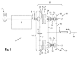
- a drive motor 3 for example a diesel engine, provides a drive power for a PTO transmission 12 via a transmission input shaft 5. Besides provides the drive motor 3 drive power for example, a traction drive 4 of the tractor 1 ready.
- the transmission input shaft 5 can be brought into drive connection via a form-fitting clutch, for example in the form of a shift sleeve 6 or a dog clutch, to the PTO gearbox 12, in particular to an input shaft 15 of the PTO gearbox 12.
- the input shaft 15 coincides with a first drive shaft 21 of a subtransmission 13, which is still to be explained.
- opening and closing the shift sleeve 6 can be a drive connection between the drive motor 3 and the PTO gear 12 interrupt or produce.
- the intermediate gear 13 essentially comprises a toothed wheel 22 which is arranged on a first drive shaft 21, a toothed wheel 32 which is arranged on a second drive shaft 31 spaced parallel thereto, and an intermediate wheel 7 which is connected to the drive shafts 21, 31 parallel axis of rotation 8 is rotatably mounted.
- the first drive shaft 21 of the intermediate gear 13 coincides in the illustrated embodiment with the input shaft 15 of the power take-off 12.
- the intermediate gear 7 meshes with the gear 22 of the first drive shaft 21 and with the gear 32 of the second drive shaft 31.
- the gears 22 and 32 and the associated drive shafts 21 and 31 of the intermediate gear 13 are due to the gear 22, idler gear 7 and gear 32 formed gear assembly drivingly coupled, ie between them there is a constant gear ratio i z .
- the drive shafts 22 and 32 have a same direction of rotation.
- the gear 22 has a larger diameter than the gear 32, with the result that the drive shaft 31 always rotates faster in a fixed speed ratio than the drive shaft 21st
- the first drive shaft 21 can be brought into drive connection via a first multi-plate clutch 23 with a first transmission shaft 27 coaxial therewith.
- the first gear shaft 27 is associated with a set consisting of two gears 24 and 26.
- the gears 24 and 26 are positively connected by means of an interposed sliding movable shift sleeve 25 with the first transmission shaft 27.
- the gears 24 and 26 mesh respectively with a gear 9 and 10, wherein the gears 9 and 10 are connected to the first transmission shaft 27 parallel to the PTO shaft 11.
- a gear pair formed from the gear 24 and the gear 9 has a different ratio than a formed from the gear 26 and the gear 10 gear pair. In this way, the gear pairs 24, 9 and the gear pairings 26, 10 different gear ratios G n within the PTO 12.
- the gear pair 34, 9 forms a second gear G 2
- the gear pair 36, 10 forms a fourth gear G 4 of the PTO 12.
- the transmission gear G 2 or G 4 can be produced by 35 by moving the shift sleeve a corresponding gear G 2 or G 4 inserted (preselection) and the second multi-plate clutch 33 is closed (engaging).
- a previously described by way of example with reference to the first transmission gear G 1 and the second gear G 2 shift can be performed accordingly between other gear ratios and in the reverse direction (from a higher to a lower gear). If it is desired to switch between two even (G 2 , G 4 ) or two odd (G 1 , G 3 ) gear stages under load, this can preferably be done automatically by briefly interposing an intermediate gear stage G 2 or G 3 .
- balers 2 have in their drive train on a high moment of inertia (and / or load torque). Accordingly, when starting, for example, a baler 2, a high torque must be applied.
- tractor 1 and baler 2 advantageously allows a start of the stationary baler 2 using a functionality of the PTO gear 12 described below. Accordingly, at a respective preselected gear ratio G n in each of the partial gear 20, 30 simultaneously both multi-plate clutches 23, 33 closed , During this closing operation, it is possible (with driven input shaft 15 of the power take-off 12), via the multi-plate clutch 23, a torque from the first drive shaft 21 to the first transmission shaft 27 and via the second multi-plate clutch 33 to transmit torque from the second drive shaft 31 to the second transmission shaft 37.
- the first gear shaft 27 and the second gear shaft 37 generate via their respective selected gear ratio G n at the PTO a rectified torque.
- both multi-disc clutches 23, 33 are available for this coupling process, so that due to the increased friction surface a respectively reduced stress on the multi-disc clutches 22, 23, and thus less wear occurs on these. Furthermore, using both multi-plate clutches 23, 33, if required, a particularly high torque at the PTO shaft 11 can be generated. It can thus also balers 2 - or general equipment - with high moment of inertia (and / or load torque) are started or can take place in a shorter time. The process of simultaneous closing of the multi-plate clutches 22, 33 is expediently carried out only as long as until at one of the multi-plate clutches 23, 33 a synchronization is achieved.
- Fig. 2 is shown a schematic view of a situation in which a tractor 1 drives a drawn from the tractor 1 baler 2 on the rear-side PTO 11.
- the in Fig. 2 shown tractor 1 has a PTO powertrain including power take-off 12 such as with reference to Fig. 1 explained on.
- the baler 2 has various working and delivery units, which must be supplied with drive power during harvesting, ie in particular during the processing of crop to pressed bales.
- the baler 2 has a main gear 17, from which, for example, an oscillating plunger (unspecified) can be driven.
- Other work and delivery units not to be explained in more detail here can be drivingly connected to the main transmission 17.
- the main gear 17 is on the drive shaft 14 which is in drive connection with the PTO 11 of the tractor 1, driven.
- a powertrain formed from the various tractor and equipment components generally has significant inertia, depending on the type and size of construction, so that merely disconnecting the drive connection from the drive motor 3 results in a long run-on of the components still in motion these come to a standstill due to friction.
- High follow-up times can represent an increased safety hazard if, for example, a machine operator or a third party are in the vicinity of moving machine parts.
- a long wait for the actual standstill leads to a mostly unwanted loss of time during harvesting or labor input.
- the simultaneous coupling leads to a reduction of Relative speeds in the closing multi-plate clutches 23, 33 and thus to decelerating the self-locking PTO 12.
- An active braking of the PTO 11 and also about the attachment (here: baler 2) takes place.
- the clutch surfaces of both multi-plate clutches 23 and 33 are available as an effective braking surface, so that a high braking effect can be achieved. Long follow-up times of implements can be avoided in this way and safety can be increased.
- the braking method thus performed has the advantage that - in the presence of a corresponding PTO gear 12 - no additional brake and no additional actuator are required, but that the existing already at the PTO 12 multi-plate clutches 23, 33 are used as brakes.
- the preferred prior to the initiation of the braking operation interruption of the drive connection relative to the drive motor 3 can be done in a relatively inexpensive manner by a compact, positive coupling in the form of a shift sleeve 6.
- the power take-off 12 or a tractor equipped with it 1 is also suitable for driving implements that do not have their own brake despite high inertia of the drive train.
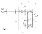
- the idler gear 40 meshes with the gear 34 of the second gear shaft 37 and the gear 9 of the PTO shaft 11, and meshes the idler 41 at the same time with the gear 36 of the second gear shaft 37 and the gear 10 of the PTO shaft 11.
- the PTO 12 according to the Fig. 3 shown second embodiment corresponds to basic functions, in particular with regard to the number of selectable gear ratios the first embodiment.
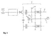
- Fig. 4 shows a power take-off 12 according to a third embodiment of the invention.
- the power take-off 12 according to the third embodiment corresponds in essential features to the basis of Fig. 1 explained first embodiment. To avoid repetition is therefore on the zu Fig. 1 Referenced remarks and is based on a designation of equivalent elements in Fig. 4 waived.
- an additional gear 28 is fixedly arranged on the first transmission shaft 27. This meshes with an additional PTO shaft 11 associated gear 16 which is fastened by means of a shift sleeve 18 relative to the PTO shaft 11 and detachable from it.
- this fifth transmission gear ratio G 5 could be designed for example as a fast economy PTO passage (1000e).
- An advantage of the structural design is that due to the arrangement of the shift sleeve 18 on the PTO 11, the axial length of the PTO 12 in spite of further transmission gear hardly increased and also the other structure is not changed.
- the drive connection of a transmission gear stage is not alone on exactly one of the transmission shafts (27 or 37) and the PTO 11 is made, but that this over both transmission shafts (27 and 37) and the PTO shaft 11 extends.
- one of the PTO 11 associated gear 9 and 10 is brought into a relation to the PTO 11 loose state to drive in meshing with gears 24, 34 and 26, 36 of both transmission shafts 27, 37 of one of the transmission shafts 27, 37th to transmit to each other 37, 27.
- the PTO transmission 12 according to the fourth embodiment thus achieved with the same number of gears - and thus compared to the first embodiment of unchanged size - an increased number of switchable gears.
Landscapes
- Engineering & Computer Science (AREA)
- Chemical & Material Sciences (AREA)
- Combustion & Propulsion (AREA)
- Transportation (AREA)
- Mechanical Engineering (AREA)
- Arrangement And Driving Of Transmission Devices (AREA)
Applications Claiming Priority (1)
| Application Number | Priority Date | Filing Date | Title |
|---|---|---|---|
| DE102013110316.2A DE102013110316A1 (de) | 2013-09-19 | 2013-09-19 | Zapfwellengetriebe für eine landwirtschaftliche Arbeitsmaschine |
Publications (3)
| Publication Number | Publication Date |
|---|---|
| EP2853431A2 true EP2853431A2 (fr) | 2015-04-01 |
| EP2853431A3 EP2853431A3 (fr) | 2015-07-01 |
| EP2853431B1 EP2853431B1 (fr) | 2018-11-14 |
Family
ID=51176161
Family Applications (1)
| Application Number | Title | Priority Date | Filing Date |
|---|---|---|---|
| EP14176257.5A Not-in-force EP2853431B1 (fr) | 2013-09-19 | 2014-07-09 | Transmission de prise de force pour machine agricole |
Country Status (2)
| Country | Link |
|---|---|
| EP (1) | EP2853431B1 (fr) |
| DE (1) | DE102013110316A1 (fr) |
Cited By (8)
| Publication number | Priority date | Publication date | Assignee | Title |
|---|---|---|---|---|
| EP3085567A3 (fr) * | 2015-04-20 | 2016-12-21 | ZF Friedrichshafen AG | Pignon prise de force et engin agricole |
| EP3138719A1 (fr) * | 2015-09-04 | 2017-03-08 | ZF Friedrichshafen AG | Dispositif d'entrainement d'une prise de force |
| CN112013086A (zh) * | 2019-05-29 | 2020-12-01 | 采埃孚股份公司 | 辅助动力输出变速器和农用作业机器 |
| WO2021146478A1 (fr) | 2020-01-17 | 2021-07-22 | Zimeno, Inc. Dba Monarch Tractor | Commande de prise de force |
| IT202000027543A1 (it) * | 2020-11-17 | 2022-05-17 | Cnh Ind Italia Spa | Assieme di presa di potenza stagionale migliorata per un veicolo da lavoro e relativo metodo di disinnesto |
| EP4073400A1 (fr) * | 2019-12-11 | 2022-10-19 | Punch Powertrain PSA e-transmissions NV | Système de transmission pour une véhicule |
| WO2024013078A1 (fr) * | 2022-07-11 | 2024-01-18 | Zf Friedrichshafen Ag | Transmission à changement de vitesses pour une transmission de véhicule à moteur du type à changement de gamme |
| CN119872211A (zh) * | 2025-03-27 | 2025-04-25 | 潍柴雷沃智慧农业科技股份有限公司 | 一种多功能电动拖拉机 |
Families Citing this family (7)
| Publication number | Priority date | Publication date | Assignee | Title |
|---|---|---|---|---|
| DE102015206877A1 (de) * | 2015-04-16 | 2016-10-20 | Zf Friedrichshafen Ag | Splittergetriebe, Gesamtgetriebe und landwirtschaftliche Arbeitsmaschine |
| CN109808790A (zh) * | 2019-02-15 | 2019-05-28 | 东北大学秦皇岛分校 | 一种用于电驱足式机器人的新型动力系统 |
| DE102021113560A1 (de) * | 2021-05-26 | 2022-12-01 | Deere & Company | Zapfwellengetriebe und landwirtschaftliches Nutzfahrzeug |
| DE102022004852A1 (de) * | 2022-12-21 | 2024-06-27 | Claas Saulgau Gmbh | Mulcheinrichtung und Erntemaschine oder Zugfahrzeug mit einer Mulcheinrichtung |
| DE102023206307B4 (de) * | 2023-07-04 | 2025-09-11 | Zf Friedrichshafen Ag | Lastschaltbares Getriebe und Verfahren zum Schalten eines lastschaltbaren Getriebes |
| DE102024204185B4 (de) * | 2024-05-06 | 2026-01-08 | Zf Friedrichshafen Ag | Doppelkupplungsgetriebegruppe, Gruppengetriebe und Arbeitsmaschine |
| US12365241B1 (en) | 2024-06-25 | 2025-07-22 | Deere & Company | Axial shifter assembly for a transmission |
Citations (1)
| Publication number | Priority date | Publication date | Assignee | Title |
|---|---|---|---|---|
| DE102011084623A1 (de) | 2011-10-17 | 2013-04-18 | Zf Friedrichshafen Ag | Zapfwellengetriebe |
Family Cites Families (5)
| Publication number | Priority date | Publication date | Assignee | Title |
|---|---|---|---|---|
| US5012909A (en) * | 1989-01-26 | 1991-05-07 | Kubota Ltd. | Change-speed control construction |
| US5058455A (en) * | 1989-08-31 | 1991-10-22 | Kanzaki Kokyukoki Mfg., Ltd. | Transmission assembly for tractor |
| US6851328B2 (en) * | 2002-04-18 | 2005-02-08 | Kubota Corporation | Control apparatus for transmission |
| WO2005088150A1 (fr) * | 2004-03-16 | 2005-09-22 | Yanmar Co., Ltd. | Dispositif de vannes hydrauliques pour véhicule de travail |
| GB2433299A (en) * | 2005-12-17 | 2007-06-20 | Agco Gmbh | Power take-off with dual integral multi-disc clutches engaged simultaneously |
-
2013
- 2013-09-19 DE DE102013110316.2A patent/DE102013110316A1/de not_active Withdrawn
-
2014
- 2014-07-09 EP EP14176257.5A patent/EP2853431B1/fr not_active Not-in-force
Patent Citations (1)
| Publication number | Priority date | Publication date | Assignee | Title |
|---|---|---|---|---|
| DE102011084623A1 (de) | 2011-10-17 | 2013-04-18 | Zf Friedrichshafen Ag | Zapfwellengetriebe |
Cited By (11)
| Publication number | Priority date | Publication date | Assignee | Title |
|---|---|---|---|---|
| EP3085567A3 (fr) * | 2015-04-20 | 2016-12-21 | ZF Friedrichshafen AG | Pignon prise de force et engin agricole |
| EP3138719A1 (fr) * | 2015-09-04 | 2017-03-08 | ZF Friedrichshafen AG | Dispositif d'entrainement d'une prise de force |
| CN112013086A (zh) * | 2019-05-29 | 2020-12-01 | 采埃孚股份公司 | 辅助动力输出变速器和农用作业机器 |
| EP4073400A1 (fr) * | 2019-12-11 | 2022-10-19 | Punch Powertrain PSA e-transmissions NV | Système de transmission pour une véhicule |
| US12158197B2 (en) | 2019-12-11 | 2024-12-03 | Punch Powertrain Psa E-Transmissions Nv | Transmission system for a vehicle |
| WO2021146478A1 (fr) | 2020-01-17 | 2021-07-22 | Zimeno, Inc. Dba Monarch Tractor | Commande de prise de force |
| EP4090146A4 (fr) * | 2020-01-17 | 2024-02-14 | Zimeno, Inc. DBA Monarch Tractor | Commande de prise de force |
| IT202000027543A1 (it) * | 2020-11-17 | 2022-05-17 | Cnh Ind Italia Spa | Assieme di presa di potenza stagionale migliorata per un veicolo da lavoro e relativo metodo di disinnesto |
| EP4000981A1 (fr) * | 2020-11-17 | 2022-05-25 | CNH Industrial Italia S.p.A. | Ensemble prise de force saisonnière améliorée pour un engin de chantierl et procédé de désolidarisation associé |
| WO2024013078A1 (fr) * | 2022-07-11 | 2024-01-18 | Zf Friedrichshafen Ag | Transmission à changement de vitesses pour une transmission de véhicule à moteur du type à changement de gamme |
| CN119872211A (zh) * | 2025-03-27 | 2025-04-25 | 潍柴雷沃智慧农业科技股份有限公司 | 一种多功能电动拖拉机 |
Also Published As
| Publication number | Publication date |
|---|---|
| EP2853431B1 (fr) | 2018-11-14 |
| EP2853431A3 (fr) | 2015-07-01 |
| DE102013110316A1 (de) | 2015-03-19 |
Similar Documents
| Publication | Publication Date | Title |
|---|---|---|
| EP2853431B1 (fr) | Transmission de prise de force pour machine agricole | |
| DE10317693B4 (de) | Steuervorrichtung für ein Getriebe | |
| AT519295A2 (de) | Drehmomentübertragungsvorrichtung für Hybridantriebe | |
| EP0716248A1 (fr) | Transmission de changement de vitesse sous charge avec transmission orbitale à cinq arbres | |
| EP3543058A1 (fr) | Transmission d'arbre de prise de force | |
| WO2016202515A1 (fr) | Système de boîte de vitesses, ensemble boîte de vitesses et engin agricole | |
| EP3754226B1 (fr) | Boîte de vitesses à commande sous charge | |
| DE102018204291A1 (de) | Antriebsvorrichtung für ein elektrisch betriebenes Fahrzeug | |
| DE102017222705B4 (de) | Getriebe für ein Kraftfahrzeug | |
| DE102007062457A1 (de) | Getriebeanordnung eines landwirtschaftlichen oder industriellen Nutzfahrzeugs | |
| EP2857246A2 (fr) | Machine agricole | |
| DE102020202008B4 (de) | Leistungsverzweigtes stufenloses Getriebe | |
| DE102019207925A1 (de) | Nebenabtriebsgetriebe und landwirtschaftliche Arbeitsmaschine | |
| DE102012208161A1 (de) | Getriebe, insbesondere automatisiertes Schaltgetriebe, sowie Verwendung einer Viergang-Schaltgruppe und Kraftfahrzeug | |
| EP4098908B1 (fr) | Engrenage prise de force et véhicule utilitaire agricole | |
| EP3085567A2 (fr) | Pignon prise de force et engin agricole | |
| DE102013220919B4 (de) | Verfahren zur Steuerung eines stufenloses Getriebes | |
| DE102018217870A1 (de) | Getriebe für ein Kraftfahrzeug | |
| DE1085045B (de) | Getriebe, insbesondere fuer landwirtschaftlich genutzte Motorfahrzeuge | |
| DE102015212047A1 (de) | Nebenabtriebsgetriebe und landwirtschaftliche Arbeitsmaschine | |
| DE102015223249A1 (de) | Verfahren zur Steuerung eines stufenlosen Getriebes | |
| DE102021211663B3 (de) | Landmaschinengetriebe, insbesondere für einen Ackerschlepper | |
| EP3034348A1 (fr) | Boîte de transfert destinée à répartir un couple sur au moins un premier et un second arbre primaire d'un véhicule automobile | |
| DE102020201692B3 (de) | Leistungsverzweigtes stufenloses Getriebe | |
| DE102020202417B3 (de) | Leistungsverzweigtes stufenloses Getriebe |
Legal Events
| Date | Code | Title | Description |
|---|---|---|---|
| PUAI | Public reference made under article 153(3) epc to a published international application that has entered the european phase |
Free format text: ORIGINAL CODE: 0009012 |
|
| 17P | Request for examination filed |
Effective date: 20140709 |
|
| AK | Designated contracting states |
Kind code of ref document: A2 Designated state(s): AL AT BE BG CH CY CZ DE DK EE ES FI FR GB GR HR HU IE IS IT LI LT LU LV MC MK MT NL NO PL PT RO RS SE SI SK SM TR |
|
| AX | Request for extension of the european patent |
Extension state: BA ME |
|
| PUAL | Search report despatched |
Free format text: ORIGINAL CODE: 0009013 |
|
| AK | Designated contracting states |
Kind code of ref document: A3 Designated state(s): AL AT BE BG CH CY CZ DE DK EE ES FI FR GB GR HR HU IE IS IT LI LT LU LV MC MK MT NL NO PL PT RO RS SE SI SK SM TR |
|
| AX | Request for extension of the european patent |
Extension state: BA ME |
|
| RIC1 | Information provided on ipc code assigned before grant |
Ipc: B60K 17/28 20060101ALI20150528BHEP Ipc: F16H 3/08 20060101ALI20150528BHEP Ipc: B60K 17/02 20060101AFI20150528BHEP Ipc: F16H 3/00 20060101ALI20150528BHEP |
|
| R17P | Request for examination filed (corrected) |
Effective date: 20160104 |
|
| RBV | Designated contracting states (corrected) |
Designated state(s): AL AT BE BG CH CY CZ DE DK EE ES FI FR GB GR HR HU IE IS IT LI LT LU LV MC MK MT NL NO PL PT RO RS SE SI SK SM TR |
|
| 18D | Application deemed to be withdrawn |
Effective date: 20160119 |
|
| STAA | Information on the status of an ep patent application or granted ep patent |
Free format text: STATUS: REQUEST FOR EXAMINATION WAS MADE |
|
| D18D | Application deemed to be withdrawn (deleted) | ||
| STAA | Information on the status of an ep patent application or granted ep patent |
Free format text: STATUS: EXAMINATION IS IN PROGRESS |
|
| 17Q | First examination report despatched |
Effective date: 20170921 |
|
| GRAP | Despatch of communication of intention to grant a patent |
Free format text: ORIGINAL CODE: EPIDOSNIGR1 |
|
| STAA | Information on the status of an ep patent application or granted ep patent |
Free format text: STATUS: GRANT OF PATENT IS INTENDED |
|
| INTG | Intention to grant announced |
Effective date: 20180717 |
|
| GRAS | Grant fee paid |
Free format text: ORIGINAL CODE: EPIDOSNIGR3 |
|
| GRAA | (expected) grant |
Free format text: ORIGINAL CODE: 0009210 |
|
| STAA | Information on the status of an ep patent application or granted ep patent |
Free format text: STATUS: THE PATENT HAS BEEN GRANTED |
|
| AK | Designated contracting states |
Kind code of ref document: B1 Designated state(s): AL AT BE BG CH CY CZ DE DK EE ES FI FR GB GR HR HU IE IS IT LI LT LU LV MC MK MT NL NO PL PT RO RS SE SI SK SM TR |
|
| REG | Reference to a national code |
Ref country code: CH Ref legal event code: EP Ref country code: AT Ref legal event code: REF Ref document number: 1064383 Country of ref document: AT Kind code of ref document: T Effective date: 20181115 |
|
| REG | Reference to a national code |
Ref country code: DE Ref legal event code: R096 Ref document number: 502014010039 Country of ref document: DE |
|
| REG | Reference to a national code |
Ref country code: IE Ref legal event code: FG4D Free format text: LANGUAGE OF EP DOCUMENT: GERMAN |
|
| REG | Reference to a national code |
Ref country code: NL Ref legal event code: MP Effective date: 20181114 |
|
| REG | Reference to a national code |
Ref country code: LT Ref legal event code: MG4D |
|
| PG25 | Lapsed in a contracting state [announced via postgrant information from national office to epo] |
Ref country code: ES Free format text: LAPSE BECAUSE OF FAILURE TO SUBMIT A TRANSLATION OF THE DESCRIPTION OR TO PAY THE FEE WITHIN THE PRESCRIBED TIME-LIMIT Effective date: 20181114 Ref country code: LV Free format text: LAPSE BECAUSE OF FAILURE TO SUBMIT A TRANSLATION OF THE DESCRIPTION OR TO PAY THE FEE WITHIN THE PRESCRIBED TIME-LIMIT Effective date: 20181114 Ref country code: HR Free format text: LAPSE BECAUSE OF FAILURE TO SUBMIT A TRANSLATION OF THE DESCRIPTION OR TO PAY THE FEE WITHIN THE PRESCRIBED TIME-LIMIT Effective date: 20181114 Ref country code: NO Free format text: LAPSE BECAUSE OF FAILURE TO SUBMIT A TRANSLATION OF THE DESCRIPTION OR TO PAY THE FEE WITHIN THE PRESCRIBED TIME-LIMIT Effective date: 20190214 Ref country code: BG Free format text: LAPSE BECAUSE OF FAILURE TO SUBMIT A TRANSLATION OF THE DESCRIPTION OR TO PAY THE FEE WITHIN THE PRESCRIBED TIME-LIMIT Effective date: 20190214 Ref country code: FI Free format text: LAPSE BECAUSE OF FAILURE TO SUBMIT A TRANSLATION OF THE DESCRIPTION OR TO PAY THE FEE WITHIN THE PRESCRIBED TIME-LIMIT Effective date: 20181114 Ref country code: LT Free format text: LAPSE BECAUSE OF FAILURE TO SUBMIT A TRANSLATION OF THE DESCRIPTION OR TO PAY THE FEE WITHIN THE PRESCRIBED TIME-LIMIT Effective date: 20181114 Ref country code: IS Free format text: LAPSE BECAUSE OF FAILURE TO SUBMIT A TRANSLATION OF THE DESCRIPTION OR TO PAY THE FEE WITHIN THE PRESCRIBED TIME-LIMIT Effective date: 20190314 |
|
| PG25 | Lapsed in a contracting state [announced via postgrant information from national office to epo] |
Ref country code: SE Free format text: LAPSE BECAUSE OF FAILURE TO SUBMIT A TRANSLATION OF THE DESCRIPTION OR TO PAY THE FEE WITHIN THE PRESCRIBED TIME-LIMIT Effective date: 20181114 Ref country code: RS Free format text: LAPSE BECAUSE OF FAILURE TO SUBMIT A TRANSLATION OF THE DESCRIPTION OR TO PAY THE FEE WITHIN THE PRESCRIBED TIME-LIMIT Effective date: 20181114 Ref country code: NL Free format text: LAPSE BECAUSE OF FAILURE TO SUBMIT A TRANSLATION OF THE DESCRIPTION OR TO PAY THE FEE WITHIN THE PRESCRIBED TIME-LIMIT Effective date: 20181114 Ref country code: PT Free format text: LAPSE BECAUSE OF FAILURE TO SUBMIT A TRANSLATION OF THE DESCRIPTION OR TO PAY THE FEE WITHIN THE PRESCRIBED TIME-LIMIT Effective date: 20190314 Ref country code: GR Free format text: LAPSE BECAUSE OF FAILURE TO SUBMIT A TRANSLATION OF THE DESCRIPTION OR TO PAY THE FEE WITHIN THE PRESCRIBED TIME-LIMIT Effective date: 20190215 Ref country code: AL Free format text: LAPSE BECAUSE OF FAILURE TO SUBMIT A TRANSLATION OF THE DESCRIPTION OR TO PAY THE FEE WITHIN THE PRESCRIBED TIME-LIMIT Effective date: 20181114 |
|
| PG25 | Lapsed in a contracting state [announced via postgrant information from national office to epo] |
Ref country code: DK Free format text: LAPSE BECAUSE OF FAILURE TO SUBMIT A TRANSLATION OF THE DESCRIPTION OR TO PAY THE FEE WITHIN THE PRESCRIBED TIME-LIMIT Effective date: 20181114 Ref country code: CZ Free format text: LAPSE BECAUSE OF FAILURE TO SUBMIT A TRANSLATION OF THE DESCRIPTION OR TO PAY THE FEE WITHIN THE PRESCRIBED TIME-LIMIT Effective date: 20181114 Ref country code: IT Free format text: LAPSE BECAUSE OF FAILURE TO SUBMIT A TRANSLATION OF THE DESCRIPTION OR TO PAY THE FEE WITHIN THE PRESCRIBED TIME-LIMIT Effective date: 20181114 Ref country code: PL Free format text: LAPSE BECAUSE OF FAILURE TO SUBMIT A TRANSLATION OF THE DESCRIPTION OR TO PAY THE FEE WITHIN THE PRESCRIBED TIME-LIMIT Effective date: 20181114 |
|
| REG | Reference to a national code |
Ref country code: DE Ref legal event code: R097 Ref document number: 502014010039 Country of ref document: DE |
|
| PG25 | Lapsed in a contracting state [announced via postgrant information from national office to epo] |
Ref country code: SM Free format text: LAPSE BECAUSE OF FAILURE TO SUBMIT A TRANSLATION OF THE DESCRIPTION OR TO PAY THE FEE WITHIN THE PRESCRIBED TIME-LIMIT Effective date: 20181114 Ref country code: SK Free format text: LAPSE BECAUSE OF FAILURE TO SUBMIT A TRANSLATION OF THE DESCRIPTION OR TO PAY THE FEE WITHIN THE PRESCRIBED TIME-LIMIT Effective date: 20181114 Ref country code: EE Free format text: LAPSE BECAUSE OF FAILURE TO SUBMIT A TRANSLATION OF THE DESCRIPTION OR TO PAY THE FEE WITHIN THE PRESCRIBED TIME-LIMIT Effective date: 20181114 |
|
| PLBE | No opposition filed within time limit |
Free format text: ORIGINAL CODE: 0009261 |
|
| STAA | Information on the status of an ep patent application or granted ep patent |
Free format text: STATUS: NO OPPOSITION FILED WITHIN TIME LIMIT |
|
| 26N | No opposition filed |
Effective date: 20190815 |
|
| PG25 | Lapsed in a contracting state [announced via postgrant information from national office to epo] |
Ref country code: SI Free format text: LAPSE BECAUSE OF FAILURE TO SUBMIT A TRANSLATION OF THE DESCRIPTION OR TO PAY THE FEE WITHIN THE PRESCRIBED TIME-LIMIT Effective date: 20181114 |
|
| PG25 | Lapsed in a contracting state [announced via postgrant information from national office to epo] |
Ref country code: MC Free format text: LAPSE BECAUSE OF FAILURE TO SUBMIT A TRANSLATION OF THE DESCRIPTION OR TO PAY THE FEE WITHIN THE PRESCRIBED TIME-LIMIT Effective date: 20181114 |
|
| REG | Reference to a national code |
Ref country code: CH Ref legal event code: PL |
|
| GBPC | Gb: european patent ceased through non-payment of renewal fee |
Effective date: 20190731 |
|
| PG25 | Lapsed in a contracting state [announced via postgrant information from national office to epo] |
Ref country code: TR Free format text: LAPSE BECAUSE OF FAILURE TO SUBMIT A TRANSLATION OF THE DESCRIPTION OR TO PAY THE FEE WITHIN THE PRESCRIBED TIME-LIMIT Effective date: 20181114 |
|
| PG25 | Lapsed in a contracting state [announced via postgrant information from national office to epo] |
Ref country code: GB Free format text: LAPSE BECAUSE OF NON-PAYMENT OF DUE FEES Effective date: 20190731 |
|
| PG25 | Lapsed in a contracting state [announced via postgrant information from national office to epo] |
Ref country code: LI Free format text: LAPSE BECAUSE OF NON-PAYMENT OF DUE FEES Effective date: 20190731 Ref country code: LU Free format text: LAPSE BECAUSE OF NON-PAYMENT OF DUE FEES Effective date: 20190709 Ref country code: CH Free format text: LAPSE BECAUSE OF NON-PAYMENT OF DUE FEES Effective date: 20190731 |
|
| PG25 | Lapsed in a contracting state [announced via postgrant information from national office to epo] |
Ref country code: IE Free format text: LAPSE BECAUSE OF NON-PAYMENT OF DUE FEES Effective date: 20190709 |
|
| REG | Reference to a national code |
Ref country code: AT Ref legal event code: MM01 Ref document number: 1064383 Country of ref document: AT Kind code of ref document: T Effective date: 20190709 |
|
| PG25 | Lapsed in a contracting state [announced via postgrant information from national office to epo] |
Ref country code: AT Free format text: LAPSE BECAUSE OF NON-PAYMENT OF DUE FEES Effective date: 20190709 |
|
| PG25 | Lapsed in a contracting state [announced via postgrant information from national office to epo] |
Ref country code: RO Free format text: LAPSE BECAUSE OF FAILURE TO SUBMIT A TRANSLATION OF THE DESCRIPTION OR TO PAY THE FEE WITHIN THE PRESCRIBED TIME-LIMIT Effective date: 20181114 |
|
| PG25 | Lapsed in a contracting state [announced via postgrant information from national office to epo] |
Ref country code: CY Free format text: LAPSE BECAUSE OF FAILURE TO SUBMIT A TRANSLATION OF THE DESCRIPTION OR TO PAY THE FEE WITHIN THE PRESCRIBED TIME-LIMIT Effective date: 20181114 |
|
| PG25 | Lapsed in a contracting state [announced via postgrant information from national office to epo] |
Ref country code: MT Free format text: LAPSE BECAUSE OF FAILURE TO SUBMIT A TRANSLATION OF THE DESCRIPTION OR TO PAY THE FEE WITHIN THE PRESCRIBED TIME-LIMIT Effective date: 20181114 Ref country code: HU Free format text: LAPSE BECAUSE OF FAILURE TO SUBMIT A TRANSLATION OF THE DESCRIPTION OR TO PAY THE FEE WITHIN THE PRESCRIBED TIME-LIMIT; INVALID AB INITIO Effective date: 20140709 |
|
| PG25 | Lapsed in a contracting state [announced via postgrant information from national office to epo] |
Ref country code: MK Free format text: LAPSE BECAUSE OF FAILURE TO SUBMIT A TRANSLATION OF THE DESCRIPTION OR TO PAY THE FEE WITHIN THE PRESCRIBED TIME-LIMIT Effective date: 20181114 |
|
| P01 | Opt-out of the competence of the unified patent court (upc) registered |
Effective date: 20230515 |
|
| PGFP | Annual fee paid to national office [announced via postgrant information from national office to epo] |
Ref country code: DE Payment date: 20240719 Year of fee payment: 11 |
|
| PGFP | Annual fee paid to national office [announced via postgrant information from national office to epo] |
Ref country code: BE Payment date: 20240719 Year of fee payment: 11 |
|
| PGFP | Annual fee paid to national office [announced via postgrant information from national office to epo] |
Ref country code: FR Payment date: 20240730 Year of fee payment: 11 |
|
| REG | Reference to a national code |
Ref country code: DE Ref legal event code: R119 Ref document number: 502014010039 Country of ref document: DE |
|
| REG | Reference to a national code |
Ref country code: BE Ref legal event code: MM Effective date: 20250731 |
|
| PG25 | Lapsed in a contracting state [announced via postgrant information from national office to epo] |
Ref country code: DE Free format text: LAPSE BECAUSE OF NON-PAYMENT OF DUE FEES Effective date: 20260203 |
|
| PG25 | Lapsed in a contracting state [announced via postgrant information from national office to epo] |
Ref country code: BE Free format text: LAPSE BECAUSE OF NON-PAYMENT OF DUE FEES Effective date: 20250731 |
|
| PG25 | Lapsed in a contracting state [announced via postgrant information from national office to epo] |
Ref country code: FR Free format text: LAPSE BECAUSE OF NON-PAYMENT OF DUE FEES Effective date: 20250731 |