EP2853455A2 - Elektrische Bremsvorrichtung für ein Fahrzeug - Google Patents
Elektrische Bremsvorrichtung für ein Fahrzeug Download PDFInfo
- Publication number
- EP2853455A2 EP2853455A2 EP20140186749 EP14186749A EP2853455A2 EP 2853455 A2 EP2853455 A2 EP 2853455A2 EP 20140186749 EP20140186749 EP 20140186749 EP 14186749 A EP14186749 A EP 14186749A EP 2853455 A2 EP2853455 A2 EP 2853455A2
- Authority
- EP
- European Patent Office
- Prior art keywords
- connector
- terminal
- electric
- electric power
- electric motor
- Prior art date
- Legal status (The legal status is an assumption and is not a legal conclusion. Google has not performed a legal analysis and makes no representation as to the accuracy of the status listed.)
- Granted
Links
Images




Classifications
-
- F—MECHANICAL ENGINEERING; LIGHTING; HEATING; WEAPONS; BLASTING
- F16—ENGINEERING ELEMENTS AND UNITS; GENERAL MEASURES FOR PRODUCING AND MAINTAINING EFFECTIVE FUNCTIONING OF MACHINES OR INSTALLATIONS; THERMAL INSULATION IN GENERAL
- F16D—COUPLINGS FOR TRANSMITTING ROTATION; CLUTCHES; BRAKES
- F16D65/00—Parts or details
- F16D65/14—Actuating mechanisms for brakes; Means for initiating operation at a predetermined position
- F16D65/16—Actuating mechanisms for brakes; Means for initiating operation at a predetermined position arranged in or on the brake
- F16D65/18—Actuating mechanisms for brakes; Means for initiating operation at a predetermined position arranged in or on the brake adapted for drawing members together, e.g. for disc brakes
-
- B—PERFORMING OPERATIONS; TRANSPORTING
- B60—VEHICLES IN GENERAL
- B60T—VEHICLE BRAKE CONTROL SYSTEMS OR PARTS THEREOF; BRAKE CONTROL SYSTEMS OR PARTS THEREOF, IN GENERAL; ARRANGEMENT OF BRAKING ELEMENTS ON VEHICLES IN GENERAL; PORTABLE DEVICES FOR PREVENTING UNWANTED MOVEMENT OF VEHICLES; VEHICLE MODIFICATIONS TO FACILITATE COOLING OF BRAKES
- B60T13/00—Transmitting braking action from initiating means to ultimate brake actuator with power assistance or drive; Brake systems incorporating such transmitting means, e.g. air-pressure brake systems
- B60T13/74—Transmitting braking action from initiating means to ultimate brake actuator with power assistance or drive; Brake systems incorporating such transmitting means, e.g. air-pressure brake systems with electrical assistance or drive
- B60T13/741—Transmitting braking action from initiating means to ultimate brake actuator with power assistance or drive; Brake systems incorporating such transmitting means, e.g. air-pressure brake systems with electrical assistance or drive acting on an ultimate actuator
-
- F—MECHANICAL ENGINEERING; LIGHTING; HEATING; WEAPONS; BLASTING
- F16—ENGINEERING ELEMENTS AND UNITS; GENERAL MEASURES FOR PRODUCING AND MAINTAINING EFFECTIVE FUNCTIONING OF MACHINES OR INSTALLATIONS; THERMAL INSULATION IN GENERAL
- F16D—COUPLINGS FOR TRANSMITTING ROTATION; CLUTCHES; BRAKES
- F16D2121/00—Type of actuator operation force
- F16D2121/18—Electric or magnetic
- F16D2121/24—Electric or magnetic using motors
-
- F—MECHANICAL ENGINEERING; LIGHTING; HEATING; WEAPONS; BLASTING
- F16—ENGINEERING ELEMENTS AND UNITS; GENERAL MEASURES FOR PRODUCING AND MAINTAINING EFFECTIVE FUNCTIONING OF MACHINES OR INSTALLATIONS; THERMAL INSULATION IN GENERAL
- F16D—COUPLINGS FOR TRANSMITTING ROTATION; CLUTCHES; BRAKES
- F16D2125/00—Components of actuators
- F16D2125/18—Mechanical mechanisms
- F16D2125/20—Mechanical mechanisms converting rotation to linear movement or vice versa
- F16D2125/34—Mechanical mechanisms converting rotation to linear movement or vice versa acting in the direction of the axis of rotation
- F16D2125/40—Screw-and-nut
-
- F—MECHANICAL ENGINEERING; LIGHTING; HEATING; WEAPONS; BLASTING
- F16—ENGINEERING ELEMENTS AND UNITS; GENERAL MEASURES FOR PRODUCING AND MAINTAINING EFFECTIVE FUNCTIONING OF MACHINES OR INSTALLATIONS; THERMAL INSULATION IN GENERAL
- F16D—COUPLINGS FOR TRANSMITTING ROTATION; CLUTCHES; BRAKES
- F16D2125/00—Components of actuators
- F16D2125/18—Mechanical mechanisms
- F16D2125/44—Mechanical mechanisms transmitting rotation
- F16D2125/46—Rotating members in mutual engagement
- F16D2125/48—Rotating members in mutual engagement with parallel stationary axes, e.g. spur gears
Definitions
- the present invention relates to an electric braking device mounted on a vehicle.
- JP-A-2007-232045 discloses a brake control device having an integrated structure in which an electric circuit unit is provided to a brake force generation unit of a brake device, and for the purpose of improving vibration resistance and heat resistance, an opening is provided in a case on a circuit side and a connection portion is arranged in a space inside the opening.
- JP-A-2007-232045 also discloses that a harness provided with an electric power line and a first signal line, and the electric circuit unit are connected by a connector (refer to Fig. 8) and the connector and a cover are integrally formed (refer to Fig. 9).
- an electric braking device in which an electric motor and a drive circuit are provided to a wheel and braking torque is generated by supplying electric power from a vehicle body side, there has been desired for not only improvement of vibration resistance and heat resistance but also consideration on flying stones and the like and improvement of water resistance.
- vibration resistance and heat resistance for example, when a vehicle travels on an unpaved road, small stones are kicked up due to rotations of wheels, thereby colliding with each member inside a wheel house. Further, when each member is wet, water remains in a concave portion or a corner portion for a long period and gradually intrudes into the device.
- the present invention has been made in view of the above circumstances, and an object of the present invention is to provide a technique which is effective to improve reliability of an electric braking device for a vehicle to which electric power and/or a signal is supplied via a connector, with respect to flying stones and the like.
- an electric braking device for a vehicle which includes a brake caliper (CPR), a pressing member (PSN), an electric motor (MTR), an electric power line (PWL), and a connector (CNC).
- the brake caliper (CPR) is provided to a wheel (WHL).
- the pressing member (PSN) is provided to the brake caliper (CPR).
- the pressing member (PSN) is driven to press a friction member (MSB) to a rotary member (KTB) which is fixed to the wheel (WHL) and rotates together with the wheel (WHL).
- the electric motor (MTR) is a power source to drive the pressing member (PSN).
- the electric power line (PWL) supplies electric power to the electric motor (MTR) from electric power sources (BAT and ALT) which are fixed to a vehicle body (BDY) of the vehicle.
- the connector (CNC) relays the electric power line (PWL).
- the connector (CNC) includes a terminal joining portion (Sgp) which joins one terminal (TP1) and another terminal (TP2) to each other.
- the one terminal (TP1) and the another terminal (TP2) are made of metal.
- the terminal joining portion (Sgp) is positioned inside the brake caliper (CPR).
- an electric braking device for a vehicle which includes a brake caliper (CPR), a pressing member (PSN), an electric motor (MTR), a signal line (SGL), and a connector (CNC).
- the signal line (SGL) allows a first electric circuit (ECU and ECV) provided in a vehicle body (BDY) of the vehicle to communicate with a second electric circuit (DRV, DFB, and DMK) provided in the brake caliper (CPR).
- the connector (CNC) relays the signal line (SGL).
- the connector (CNC) includes a terminal joining portion (Sgs) which joins one terminal (TS1) and another terminal (TP2) to each other.
- the one terminal (TS1) and the another terminal (TP2) are made of metal.
- the terminal joining portion (Sgs) is positioned inside the brake caliper (CPR).
- a male side connector and a female side connector in a combination configuring the connector (CNC) are joined (are fit) to each other inside the brake caliper (CPR). Therefore, there is no need to individually provide a protection cover (a protector) to cope with flying stones and the like.
- the brake caliper (CPR) itself becomes a protective member for the connector (CNC).
- the size of a portion of the connector (CNC) exposed outside the brake caliper (CPR) may be suppressed to be minimum necessary, and thus, probability of damage to the connector (CNC), particularly to the terminal joining portions (Sgp and Sgs) may be decreased.
- the terminal joining portions (Sgp and Sgs) are arranged inside the brake caliper (CPR), it is possible to extend the length of a water-intrusion path through which water intrudes from the surface of the brake caliper (CPR) to the terminal joining portions (Sgp and Sgs). As a result, water resistance of the terminal joining portions (Sgp and Sgs) may be improved.
- the brake caliper (CPR) include a case member (CAS) having a space to accommodate the terminal joining portions (Sgp and Sgs), and the terminal joining portions (Sgp and Sgs) be formed in the connector (CNC) by joining the another terminal (TP2 and TS2) which is introduced to the space of the case member (CAS) through an opening portion (Kkb) provided to penetrate the case member (CAS), to the one terminal (TP1 and TS1) which is arranged in the space of the case member (CAS).
- the case member (CAS) is a portion of the brake caliper (CPR), and can be configured as a member having a box-type structure including a storing space therein.
- the case member (CAS) itself which is a portion of the brake caliper (CPR) becomes the protective member of the connector (CNC). Moreover, it may be possible to extend the length of the water-intrusion path through which water intrudes from the surface of the brake caliper (CPR) to the terminal joining portions (Sgp and Sgs) through the opening portion (Kkb) of the case member (CAS).
- a vehicle including an electric braking device is provided with a braking operation member BP, a braking operation amount acquisition unit BPA, an electronic control unit ECU, electric power sources BAT and ALT, and a braking unit (a brake actuator) BRK.
- the electric braking device is a device which is configured to generate braking torque on a wheel WHL of the vehicle.
- the braking operation member BP is a member operated by a driver to reduce the speed of the vehicle.
- the braking torque of the wheel WHL is adjusted by the braking unit BRK.
- a braking force is generated in the wheel WHL, thereby reducing the speed of the traveling vehicle.
- a brake pedal which is operated by a brake pedal stepping force of the driver corresponds to the braking operation member BP.
- the braking operation amount acquisition unit BPA is provided to the braking operation member BP.
- the braking operation amount acquisition unit BPA acquires (detects) an operation amount (a braking operation amount) Bpa of the braking operation member BP operated by the driver.
- a sensor configured to detect a pressure of a master cylinder (a pressure sensor), a sensor configured to detect an operation force of the braking operation member BP (a brake pedal stepping force sensor), and a sensor configured to detect a displacement amount of the braking operation member BP (a brake pedal stroke sensor) is employed.
- the braking operation amount Bpa is calculated based on at least one of the pressure of the master cylinder, the brake pedal stepping force, and a brake pedal stroke.
- the calculated braking operation amount Bpa is input to the electronic control unit ECU (specifically, a processor CPUb which is provided in the electronic control unit ECU).
- the electronic control unit ECU has an electric circuit (a printed wiring board) including the processor CPUb and is fixed to a vehicle body BDY.
- the processor is an electronic circuit, that is, “a central processing unit (CPU)” configured to execute calculation processing.
- the printed wiring board is a plate-like component configuring the electronic circuit by fixing electronic components such as an integrated circuit, a resistor, and a capacitor to the surface thereof and connecting the electronic components through wiring.
- the electronic control unit ECU is an example of a first electric circuit of the present invention.
- a target signal calculation unit FBT is programmed.
- the target signal calculation unit FBT calculates a target pressing force (a target value) Fbt.
- the target value (a drive signal) Fbt to drive an electric motor MTR of the braking unit BRK is output to an drive circuit DRV from the electronic control unit ECU.
- the target pressing force Fbt is transmitted to the drive circuit DRV via a signal line SGL.
- Electric power to drive the electric motor MTR is supplied to the drive circuit DRV from a storage battery (a battery) BAT and the like via the electronic control unit ECU.
- the storage battery BAT and an alternator (an electric dynamo) ALT configure an electric power source to supply electric power to the electronic control unit ECU, the drive circuit DRV, and the electric motor MTR.
- the electric power sources BAT and ALT are fixed to the vehicle body BDY.
- the alternator ALT charges the storage battery BAT. Electric power (electric current) from the electric power sources BAT and ALT is supplied to the drive circuit DRV (eventually, to the electric motor MTR) via an electric power line PWL.
- a target pressing force calculation block (the target signal calculation unit) FBT calculates the target pressing force (the target signal) Fbt of a force (a pressing force) of a friction member (a brake friction pad) MSB pressing a rotary member (a brake disk) KTB.
- the target pressing force calculation block FBT is a control algorithm and is programmed in the processor CPUb in the electronic control unit ECU.
- the target signal Fbt is calculated based on the braking operation amount Bpa and a preset calculation map CHfb.
- the target signal Fbt is transmitted to the drive circuit DRV fixed to the wheel WHL via the signal line SGL.
- the braking unit (the brake actuator) BRK is provided to the wheel WHL so as to apply braking torque to the wheel WHL, thereby generating a braking force.
- the braking unit BRK reduces the speed of the traveling vehicle.
- the braking unit BRK includes a brake caliper CPR, a pressing member PSN, the electric motor MTR, a position acquisition unit MKA, a reduction gear GSK, a shaft member SFT, a screw member NJB, a pressing force acquisition unit FBA, the drive circuit DRV, and a connector CNC.
- the brake caliper (simply referred to as "caliper") CPR is provided (allocated) to the wheel WHL.
- the caliper CPR is an example of a brake caliper of the present invention.
- a float-type caliper may be employed as the caliper CPR.
- the caliper CPR is configured so as to pinch the rotary member (the brake disk) KTB via two of the friction members (the brake friction pads) MSB.
- the caliper CPR is configured to have a box-type structure. Specifically, the caliper CPR has a space in its inside, and various members (the drive circuit DRV and the like) are stored in the space.
- a portion of the caliper CPR having the box-type structure is called a case member CAS.
- the case member CAS is a portion of the caliper CPR and has a cavity in its inside. Incidentally, the caliper CPR and the case member CAS may be integrally formed or may be individually formed.
- the pressing member PSN (a brake piston) is driven (advances or retreats) so as to cause the friction member MSB to be pressed against the rotary member KTB which is fixed to the wheel WHL and rotates together with the wheel WHL.
- the friction member MSB is pressed against the rotary member KTB by driving the pressing member PSN, thereby generating a friction force.
- the pressing member PSN is an example of a pressing member of the present invention.
- the pressing member PSN has a cylindrical shape and has a center axis Jps. Therefore, the pressing member PSN is driven in a direction of the center axis Jps.
- the center axis Jps is also called a drive shaft.
- the pressing member PSN is driven by power of the electric motor MTR (a power source). Specifically, an output (rotary power around a motor shaft) of the electric motor MTR is transmitted to the shaft member SFT via the reduction gear GSK. Then, rotary power (torque around the shaft) of the shaft member SFT is converted into linear power (thrust of the pressing member in an axial direction) by a power conversion member NJB and is transmitted to the pressing member PSN. As a result, the pressing member PSN moves (advances or retreats) with respect to the rotary member KTB.
- the center axis (the drive shaft) Jps of the pressing member PSN matches a rotary axis of the shaft member SFT.
- a force (a pressing force) of the friction member MSB pressing the rotary member KTB is adjusted. Since the rotary member KTB is fixed to the wheel WHL, a friction force is generated between the friction member MSB and the rotary member KTB, thereby adjusting a braking force of the wheel WHL.
- the electric motor MTR is a power source to drive the pressing member PSN.
- the electric motor MTR is an example of an electric motor" of the present invention.
- a motor with a brush or a brushless motor can be employed as the electric motor MTR.
- a normal direction of rotation corresponds to a direction in which the friction member MSB approaches the rotary member KTB (a direction in which a pressing force increases and braking torque increases)
- a reverse direction of rotation corresponds to a direction in which the friction member MSB is separated away from the rotary member KTB (a direction in which a pressing force decreases and braking torque decreases).
- Electric power is supplied from the electric power sources BAT and ALT to the electric motor MTR via the electric power line PWL and the connector CNC.
- the position acquisition unit MKA acquires (detects) a rotor position (a rotational angle) Mka of the electric motor MTR.
- a rotational angle sensor configures the position acquisition unit MKA.
- an electric circuit DMK (corresponds to a second electric circuit of the present invention) is included so as to convert a detected position Mka into an electrical signal, thereby transmitting the electrical signal.
- the position acquisition unit MKA is provided in the electric motor MTR to be coaxial with the rotor and a commutator. That is, the position acquisition unit MKA is provided on a rotary axis of the electric motor MTR.
- the detected actual position (for example, the rotational angle) Mka is input to the drive circuit DRV (specifically, a processor CPUw in the drive circuit DRV).
- the reduction gear GSK, the shaft member SFT, and the screw member NJB configure a power transmission mechanism to transmit power of the electric motor MTR to the pressing member PSN. From power of the electric motor MTR, the reduction gear GSK decreases a rotational speed and outputs it to the shaft member SFT. A rotational output (torque) of the electric motor MTR increases in accordance with a speed reduction ratio of the reduction gear GSK so that a rotational force (torque) of the shaft member SFT can be obtained.
- the reduction gear GSK is a gear transmission mechanism and is configured to have a small diameter gear SKH and a large diameter gear DKH.
- the shaft member SFT is a rotary axis member and transmits rotational power which is transmitted from the reduction gear GSK, to the screw member NJB.
- the screw member NJB is the power conversion member (a rotational-linear power conversion mechanism) which converts the rotational power of the shaft member SFT into linear power.
- a sliding screw a trapezoid-threaded screw and the like
- a rolling screw a ball screw and the like
- the pressing force acquisition unit (an axial force sensor) FBA acquires (detects) a force (a pressing force) Fba of the pressing member PSN pressing the friction member MSB.
- the electric circuit DFB (corresponds to a second electric circuit of the present invention) is included so that the pressing force acquisition unit FBA converts a detected pressing force Fba into an electrical signal, thereby transmitting the electrical signal.
- the detected actual pressing force Fba is input to the drive circuit DRV (specifically, the processor CPUw in the drive circuit DRV).
- the pressing force acquisition unit FBA is provided between the shaft member SFT and the caliper CPR. That is, the pressing force acquisition unit FBA is provided on the rotary axis of the shaft member SFT and is fixed to the caliper CPR.
- the drive circuit DRV is the electric circuit (the printed wiring board) which drives the electric motor MTR and corresponds to a second electric circuit of the present invention.
- the processor a central processing unit
- a bridge circuit HBR are provided in the drive circuit DRV.
- a control unit CTL a control algorithm
- the drive circuit DRV drives the electric motor MTR and controls the output thereof based on the target pressing force (the target signal) Fbt.
- the target signal Fbt is transmitted to the drive circuit DRV (the processor CPUw) from the electronic control unit ECU (the processor CPUb) via the signal line SGL and the connector CNC.
- a transmission path of the target signal Fbt is that the electronic control unit ECU (the target pressing force calculation block FBT) ⁇ the signal line SGL ⁇ the connector CNC ⁇ the signal line SGL ⁇ the drive circuit DRV (the processor CPUw).
- the drive circuit DRV is arranged inside (fixed to) the case member CAS (a portion of the caliper CPR). In an electrical path (an electric power system path), the drive circuit DRV is provided in the middle between the connector CNC and the electric motor MTR.
- an electric power supplying path is that the electric power sources BAT and ALT ⁇ the electronic control unit ECU ⁇ the electric power line PWL (a first electric power line PWLa) ⁇ the connector CNC ⁇ the electric power line PWL (a second electric power line PWLb) ⁇ the drive circuit DRV (the bridge circuit HBR) ⁇ the electric power line PWL (a third electric power line PWLc) ⁇ the electric motor MTR".
- the connector CNC is formed by fixing a metallic terminal by using an insulation member such as a resin.
- the connector CNC connects components to each other or connects wiring (a cable and a harness) and a component to each other, thereby transmitting and receiving electric power and/or a signal therebetween.
- the connector CNC is provided in the case member CAS (a portion of the caliper CPR) on the wheel WHL side so as to relay at least one of the electric power line PWL and the signal line SGL.
- the connector CNC corresponds to a connector of the present invention.
- the connector CNC can be fixed thereto on the drive circuit DRV. In order to minimize the number of the components, the connector CNC can serve for both supplying electric power (relaying the electric power line PWL) and transmitting a signal (relaying the signal line SGL).
- the electric power line PWL is a series of electrical paths to supply electric power to the electric motor MTR from the electric power sources BAT and ALT.
- the electric power line PWL is relayed by the connector CNC provided to the case member CAS.
- the electric power line PWL is configured to have an electric power line (the first electric power line) PWLa which is an electrical path from the electric power sources BAT and ALT to the connector CNC via the electronic control unit ECU, an electric power line (the second electric power line) PWLb which is an electrical path from the connector CNC to the drive circuit DRV, and an electric power line (the third electric power line) PWLc which is an electrical path in the drive circuit DRV as well as an electrical path from the drive circuit DRV to the electric motor MTR.
- the first electric power line PWLa a twisted-pair cable which is formed by twisting two electrical wires can be employed.
- the twisted-pair cable since emission of electromagnetic waves from the cable is minimized compared to a simple parallel cable, an influence of the electromagnetic waves on an electronic control system can be suppressed.
- a bus bar a metallic bar which functions as an electric conductor
- the bus bar has a small wiring resistance, a voltage drop is small, and thus, the electric motor MTR can be efficiently driven.
- the bus bar since there is no need of insulation coating, the bus bar exhibits high heat dissipation, thereby making it possible to easily cope with a high current.
- the signal line SGL is a series of signal transmission paths to transmit the target signal (a target pressing force) Fbt from the electronic control unit ECU (the first electric circuit) to the drive circuit DRV (the second electric circuit) to control the electric motor MTR. That is, the signal line SGL performs communication between the electronic control unit ECU (the first electric circuit) and the drive circuit DRV (the second electric circuit).
- the signal line SGL corresponds to a signal line of the present invention.
- the signal line SGL is relayed by the connector CNC provided to the case member CAS.
- a serial communication bus can be employed as the signal line SGL.
- the serial communication bus employs a communication method in which data is transmitted by one bit in series within one communication path.
- the serial communication bus a controller area network (CAN) bus can be employed.
- the signal line SGL is configured to have a communication line (a first signal line) SGLa which is a communication path from the processor CPUb (specifically, the target pressing force calculation block FBT programmed in the processor CPUb) of the electronic control unit ECU to the connector CNC, and a communication line (a second signal line) SGLb which is a communication path from the connector CNC to the processor CPUw (specifically, an instructed energizing amount calculation block IST and the like programmed in the processor CPUw) of the drive circuit DRV.
- a bus bar can be employed as the communication line SGLb.
- the electric power line PWL and the signal line SGL are collectively called wiring (a cable and a harness).
- the connector CNC is configured to have a combination of a first connector CN1 and a second connector CN2.
- the connector CNC relays both the electric power line PWL which supplies electric power and the signal line SGL which transmits a signal.
- the connector which relays the electric power line PWL and the connector which relays the signal line SGL can be individually provided. Therefore, the connector CNC relays at least one of the electric power line PWL and the signal line SGL.
- the connector CNC is provided on the surface of the case member CAS which is a portion of the caliper CPR.
- the drive circuit DRV is the electric circuit (the printed wiring board) to drive the electric motor MTR and controls an energizing state to the electric motor MTR based on the target pressing force Fbt, thereby adjusting the output and the rotation direction of the electric motor MTR.
- the drive circuit DRV is configured to have the bridge circuit HBR, an energizing amount acquisition unit IMA, and the control unit CTL.
- Fig. 2 shows an example of the drive circuit DRV when the motor with a brush (simply referred to as "brush motor”) is employed as the electric motor MTR.
- the drive circuit DRV is configured to have the control unit CTL, the bridge circuit HBR, and the energizing amount acquisition unit IMA.
- the drive circuit DRV is stored inside the case member CAS which is a portion of the caliper CPR and is fixed thereto.
- the connector CNC is fixed to the drive circuit DRV and is electrically connected thereto via a bus bar (corresponding to the electric power line PWLb).
- the drive circuit DRV and the electric motor MTR are electrically connected to each other via a bus bar (corresponding to the electric power line PWLc).
- the bridge circuit HBR is configured to have switching elements S1 to S4.
- the switching elements S1 to S4 are elements which can turn ON (energized) and turn OFF (non-energized) a portion of the electric circuit.
- MOS-FET or IGBT is used as the switching element.
- the bridge circuit HBR is a circuit requiring no bidirectional electric power source so that the energizing direction thereof to the electric motor is changed with a unidirectional electric power source, thereby making it possible to control the rotation direction (the normal direction of rotation or the reverse direction of rotation) of the electric motor.
- the switching elements S1 to S4 are driven by the control unit CTL (a signal from a switching control block SWT), and a state of being energized/non-energized of each switching element is switched, thereby adjusting the rotation direction and output torque of the electric motor MTR.
- the bridge circuit HBR is configured to have six switching elements.
- the energized state/non-energized state of the switching element is controlled.
- the position acquisition unit MKA acquires the rotor position (the rotational angle) Mka of the electric motor MTR.
- the six switching elements configuring a three-phase bridge circuit are controlled.
- directions of coil energizing amount that is, a magnetic excitation direction
- a U-phase, a V-phase, and a W-phase of the bridge circuit are sequentially switched, thereby driving the electric motor MTR.
- the rotation direction (the normal or reverse direction of rotation) of the brushless motor is determined by a relationship between a rotor and a position of magnetic excitation.
- the energizing amount acquisition unit (for example, a current sensor) IMA is provided in the drive circuit DRV.
- the energizing amount acquisition unit IMA acquires (detects) the actual energizing amount (for example, a current actually flowing through the electric motor MTR) Ima to the electric motor MTR.
- the control unit CTL controls the energizing state (eventually, the amount and the direction of a current) to the electric motor MTR based on the target pressing force (the target value) Fbt.
- the control unit CTL is the control algorithm and is programmed in the processor CPUw in the drive circuit DRV.
- the control unit CTL is configured to have the instructed energizing amount calculation block IST, a pressing force feedback control block IPT, an energizing amount adjustment calculation block IMT, a pulse width modulation block PWM, and the switching control block SWT.
- the instructed energizing amount calculation block IST calculates an instructed energizing amount Ist based on the target pressing force Fbt and preset calculation characteristics (calculation maps) CHs1 and CHs2.
- the instructed energizing amount Ist is a target value for the energizing amount to the electric motor MTR in order to achieve the target pressing force Fbt.
- the calculation map of the instructed energizing amount Ist is configured to have two characteristics CHs1 and CHs2 in consideration of hysteresis of the braking unit BRK.
- the energizing amount is an amount of state (a variable) to control output torque of the electric motor MTR.
- a current target value of the electric motor MTR can be used as the target value of the energizing amount.
- a supplied voltage value can be used as the target energizing amount.
- the supplied voltage value can be adjusted by a duty ratio of pulse width modulation, the duty ratio can be used as the energizing amount.
- the pressing force feedback control block IPT calculates a pressing force feedback energizing amount Ipt based on the target pressing force (the target value) Fbt and an actual pressing force (actual value) Fba.
- the pressing force feedback energizing amount Ipt is calculated based on a deviation (a pressing force deviation) ⁇ Fb between the target pressing force Fbt and the actual pressing force Fba, and the preset calculation characteristics (calculation maps) CHp.
- the instructed energizing amount Ist is calculated as a value corresponding to the target pressing force Fbt, but an error may occur between the target pressing force Fbt and the actual pressing force Fba due to efficiency fluctuation of the braking unit BRK.
- the instructed energizing amount Ist is determined so as to reduce the above-described error.
- the rotor position Mka is utilized so as to be able to determine the final actual pressing force Fba. Specifically, displacement calculated based on the rotor position Mka is multiplied by a rigidity value Gcp (a value corresponding to rigidity of the caliper CPR and the friction member MSB), thereby calculating an estimated pressing force Fbe. Then, based on a detection value of the pressing force acquisition unit FBA and the estimated pressing force Fbe, the final actual pressing force Fba is calculated.
- the pressing force feedback control block IPT based on only the rotor position Mka, a pressing force feedback control can be executed. Specifically, the estimated pressing force Fbe is calculated based on the rotor position Mka and the rigidity value Gcp (a spring constant of the caliper CPR and the like). Then, based on a deviation between the target pressing force Fbt and the estimated pressing force Fbe, the pressing force feedback energizing amount Ipt is calculated. In this case, the pressing force acquisition unit FBA can be omitted.
- the energizing amount adjustment calculation block IMT calculates a target energizing amount Imt which is a final target value to the electric motor MTR.
- the instructed energizing amount Ist is adjusted by the pressing force feedback energizing amount Ipt, thereby calculating the target energizing amount Imt.
- the pressing force feedback energizing amount Ipt is added so as to calculate as the final target energizing amount Imt.
- the rotation direction of the electric motor MTR is determined based on a sign (positive and negative of a value) of the target energizing amount Imt, and the output (the rotary power) of the electric motor MTR is controlled based on magnitude of the target energizing amount Imt.
- the sign of the target energizing amount Imt is a positive sign (the target energizing amount Imt > 0)
- the electric motor MTR is driven in the normal direction of rotation (an increase direction of a pressing force)
- the sign of the target energizing amount Imt is a negative sign
- the electric motor MTR is driven in the reverse direction of rotation (a decrease direction of a pressing force).
- the electric motor MTR is controlled so as to have increased output torque as the absolute value of the target energizing amount Imt is increased, and is controlled so as to have decreased output torque as the absolute value of the target energizing amount Imt is decreased.
- the pulse width modulation block PWM calculates an instruction value (target value) to perform the pulse width modulation (PWM) based on the target energizing amount Imt. Specifically, the pulse width modulation block PWM determines the duty ratio Dut (a time ratio of ON/OFF) of a pulse width based on the target energizing amount Imt and the preset characteristics (the calculation map). Additionally, the pulse width modulation block PWM determines the rotation direction of the electric motor MTR based on a sign (a positive sign or a negative sign) of the target energizing amount Imt. For example, the rotation direction of the electric motor MTR is set to have a positive (plus) value in the normal direction of rotation and a negative (minus) value in the reverse direction of rotation.
- the rotation direction of the electric motor MTR and the energizing amount (that is, the output of the electric motor MTR) to the electric motor MTR are determined in the pulse width modulation block PWM.
- a so-called "current feedback control” can be executed.
- the detection value (for example, the actual current value) Ima of the energizing amount acquisition unit IMA is input to the pulse width modulation block PWM.
- the duty ratio Dut is corrected (finely adjusted). According to the current feedback control, a highly precise motor control can be achieved.
- the switching control block SWT outputs drive signals to the switching elements (S1 to S4) configuring the bridge circuit HBR, based on the duty ratio (target value) Dut.
- the drive signal makes an instruction whether each switching element is to be in an energized state or a non-energized state. Specifically, when the electric motor MTR is driven in the normal direction of rotation based on the duty ratio Dut, the switching elements S1 and S4 are in the energized states (ON state) and the switching elements S2 and S3 are in the non-energized states (OFF state).
- the states of energizing/non-energizing of the switching elements S1 and S4 are switched by energizing time (an energizing cycle) corresponding to the duty ratio Dut.
- the switching elements S1 and S4 are controlled to be in the non-energized states (OFF state), and the switching elements S2 and S3 are controlled to be in the energized states (ON state).
- the energizing states (switching cycles of the ON/OFF state) of the switching elements S2 and S3 are adjusted based on the duty ratio Dut. Then, as the duty ratio Dut increases, the energizing time per unit time is lengthened, and thus, a larger current flows through the electric motor MTR.
- the motor with a brush can be employed.
- a current flowing through an armature (a wire wound electromagnet) is switched in accordance with the rotary phase by a mechanical commutator CMT and a brush BLC.
- the stator side has a permanent magnet and the rotor side has the wire wound circuit (the electromagnet).
- the brush BLC abuts on the commutator CMT so as to supply electric power to the wire wound circuit (the rotor).
- the brush BLC is pressed against the commutator CMT by a spring (an elastic member), and thus, a current is commutated by rotating the commutator CMT.
- the brushless motor in addition to the motor with a brush, the brushless motor can be employed.
- the brushless motor in addition to the mechanical commutator CMT of the motor with a brush, a current is commutated by the electronic circuit.
- the brushless motor having a structure in which the rotor has a permanent magnet and the stator has a wire wound circuit (an electromagnet), the rotor position Mka is detected, and a supplying current is commutated by switching the switching element in accordance with the rotor position Mka.
- the connector CNC is configured by combining the first connector CN1 having a first terminal TP1 [TS1] and the second connector CN2 having a second terminal TP2 [TS2].
- the first connector CN1 is configured to have the first terminal TP1 [TS1] and a first housing HS1.
- the second connector CN2 is configured to have a second terminal TP2 [TS2] and a second housing HS2.
- a male terminal of which the joining portion has a convex shape, and which is also referred to as pin insertion terminal
- a female terminal of which the joining portion has a concave shape, and which is also referred to as socket insertion terminal
- the first terminals TP1 (the electric power supplying metallic terminal) and TS1 (the communication metallic terminal) are the female terminals
- the second terminals TP2 (the electric power supplying metallic terminal) and TS2 (the communication metallic terminal) are the male terminals.
- a connector including the male terminal is referred to as a "male side connector”
- a connector including the female terminal is referred to as a "female side connector”.
- the first (electric power supplying) terminal TP1 is formed in an end portion of the electric power line PWL (specifically, the second electric power line PWLb).
- the second (electric power supplying) terminal TP2 is formed in an end portion of the electric power line PWL (specifically, the first electric power line PWLa).
- the first terminal TP1 and the second terminal TP2 both of which are made of metal are fit (are joined) to each other inside the case member CAS.
- a contact portion (joining portion) in which the first terminal TP1 and the second terminal TP2 come into contact with each other is a terminal joining portion Sgp. That is, the terminal joining portion Sgp is arranged inside the case member CAS.
- the first (communication) terminal TS1 is formed in an end portion of the signal line SGL (specifically, the second communication line SGLb).
- the second (communication) terminal TS2 is formed in an end portion of the signal line SGL (specifically, the first communication line SGLa). Then, the first terminal TS1 and the second terminal TS2 both of which are made of metal are fit (are joined) to each other inside the case member CAS.
- a contact portion (joining portion) in which the first terminal TS1 and the second terminal TS2 come into contact with each other is terminal joining portion Sgs. That is, the terminal joining portion Sgs is arranged inside the case member CAS.
- the first connector CN1 (specifically, the first housing HS1) can be fixed to the drive circuit DRV.
- a bus bar can be employed as the wiring PWLb [SGLb] connecting the first terminal TP1 [TS1] of the first connector CN1, and the drive circuit DRV.
- the second connector CN2 (specifically, the second housing HS2) is inserted (is introduced) into a space inside the case member CAS through an opening portion Kkb which is provided to penetrate the case member CAS, thereby fitting to the first connector CN1.
- the first terminal TP1 [TS1] of the first connector CN1 is plugged into the second terminal TP2 [TS2] of the second connector CN2.
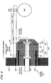
- the connector CNC is fit inside the case member CAS of the caliper CPR. That is, the terminal joining portions (the fit portions of the terminals) Sgp (the electric power supplying terminal) and Sgs (the signal transmission terminal) of the connector CNC are arranged inside the case member CAS.
- the case member CAS is a portion of the caliper CPR and is a casing which has the box-type structure including a storing space therein.
- the caliper CPR itself (the case member CAS itself) becomes a protective member for the connector CNC.
- the terminal joining portions Sgp and Sgs are arranged inside the case member CAS instead of being arranged outside the caliper CPR, the size of a portion of the connector CNC exposed outside the caliper CPR can be suppressed to be minimum necessary, and thus, probability of damage to the connector CNC, particularly to the terminal joining portions Sgp and Sgs can remarkably be decreased.
- the terminal joining portions Sgp and Sgs are arranged inside the case member CAS, the terminal joining portions Sgp and Sgs can be apart from the surface of the caliper CPR which is a water-intrusion path. That is, it is possible to extend the length of the water-intrusion path through which water intrudes from the surface of caliper CPR to the terminal joining portions Sgp and Sgs through the opening portion Kkb of the case member CAS. As a result, water resistance of the terminal joining portions Sgp and Sgs can be improved.
- a water-resistant member BSB can be provided between an inner peripheral portion of the opening portion Kkb of the case member CAS and an outer peripheral portion of the connector CNC.
- an elastomer for example, rubber
- flying stones and the like collide with the elastomer a partial cut may occur.
- the waterproofing is not performed outside the case member CAS and the sealing is performed by using the water-resistant member BSB provided between at least the inner peripheral portion of the opening portion Kkb of the case member CAS and the outer peripheral portion of the connector CNC, and thus, damage to the water-resistant member BSB due to flying stones and the like can be suppressed.
- the connector CNC (specifically, an end surface of the second connector CN2) is provided to have no step with respect to the surface of the case member CAS. That is, an end surface of the connector CNC (specifically, the second housing HS2) and the surface of the case member CAS are configured to have no step to each other in a flat state. Water is easily accumulated in a recess and the like on the surface of the case member CAS. However, the end surface of the connector CNC and the surface of the caliper form a stepless or flash surface so as to be easily dried without accumulating water even when the case member CAS is wet.
- the connector CNC (particularly, the second housing HS2) and the wiring PWL and SGL are sealed (tightly closed) by a water-resistant member BSC.
- the electric motor MTR is connected to the drive circuit DRV via the electric power line PWLc (for example, a bus bar).
- the drive circuit DRV and the electric motor MTR are fixed inside the case member CAS and stored therein.
- the terminal joining portion Sgp [Sgs] indicates the terminal joining portion Sgp between the first terminal TP1 and the second terminal TP2 for electric power lines, and the terminal joining portion Sgs between the first terminal TS1 and the second terminalTS2 for communication lines, respectively.
- the relationship between the connector CNC and the case member CAS differs from that in the first illustrative embodiment.
- the first connector CN1 is fixed to the drive circuit DRV, and the first connector CN1 is inserted into the opening portion Kkb of the case member CAS.
- the water-resistant member BSB is provided between the outer peripheral portion of the first connector CN1 and the inner peripheral portion of the opening portion Kkb.
- the second connector CN2 is fit to the first connector CN1.
- a water-resistant member BSD is provided between the inner peripheral portion of the first connector CN1 and the outer peripheral portion of the second connector CN2.
- both end surfaces of the first connector CN1 and the second connector CN2 can be caused to have no step so as to be flat with respect to the surface of the case member CAS.
- the modified illustrative embodiment exhibits the same effect as that in the first illustrative embodiment as well. That is, the case member CAS protects the terminal joining portions Sgp and Sgs for water-sealing, and protects the connector CNC and the water-resistant member BSB.
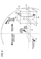
- FIG. 5 shows a partial cross section of a rotary axis Jkt (the same as the rotary axis of the wheel WHL) of the rotary member KTB when viewed being apart therefrom in a direction of the rotary axis Jkt.
- the center axis (the drive shaft) Jps of the pressing member PSN having the electric motor MTR as a power source and moving linearly moves (slides) with respect to the rotary member KTB is parallel to the rotary axis Jkt of the rotary member KTB.
- a plane Mrf formed by the center axis (the drive shaft) Jps and the rotary axis Jkt is defined as a reference plane.
- the connector CNC is positioned on the exit side with respect to the reference plane Mrf, and provided on a certain plane (also referred to as "exit plane Mex") Mex which is present in a region hidden on the reference plane Mrf when viewed in a direction perpendicular (indicated by the arrow Drf) to the reference plane Mrf from the entrance side.
- the connector CNC is arranged on the exit plane Mex positioned at the rear of the reference plane Mrf.
- the connector CNC can be installed on the certain plane Mex on the exit side which does not intersect with the reference plane Mrf.
- the caliper CPR and the case member CAS are integrally formed.
- the caliper CPR and the case member CAS are in separate bodies so as to be individually combined with each other.
- the case member CAS has a space therein (has a cavity inside thereof), and members are arranged in the space. That is, the case member CAS has the box-type structure.
- the length of an axis (for example, the length in a direction along the reference plane Mrf) of the caliper CPR (the case member CAS) can be suppressed from extending.
- the drive circuit DRV has an axially symmetrical shape, and the connector CNC is fixed thereto on a symmetrical axis Jdr.
- the drive circuit DRV is a printed wiring board which is a plate-like component configuring an electronic circuit by fixing electronic components such as an integrated circuit, a resistor, and a capacitor to the surface thereof and connecting the electronic components through wiring.
- the drive circuit DRV has the axially symmetrical shape (for example, rectangular), and the connector CNC is fixed thereto on the symmetrical axis Jdr of the drive circuit DRV. Therefore, the drive circuit DRV can be commonly used for the right and left wheels thereby making it possible to cope with the calipers CPR of the right and left wheels without increasing the number of components.
- the "axially symmetrical” refers to symmetry in which a figure overlaps itself when inverted about a certain straight line as the axis. In this case, "a certain line” is the symmetrical axis.
- the caliper CPR is configured to pinch the rotary member KTB.
- the case member CAS which is a portion of the caliper CPR is simplified so as to be indicated as a rectangular parallelepiped A-B-C-D-E-F-G-H.
- the case member CAS is divided into half.
- a side where the rotary member KTB enters the caliper CPR is referred to as an "entrance side”
- a side where the rotary member KTB escapes from the caliper CPR is referred to as an "exit side”.
- the connector CNC is provided on a certain plane (which is a plane A-B-C-D and is the exit plane Mex) of the case member CAS which is present on the escape side (a rectangular parallelepiped A-B-C-D-K-L-M-N) and does not intersect (has no intersection line) the reference plane Mrf (a plane K-L-M-N). That is, the connector CNC does not intersect the reference plane Mrf formed by the rotary axis Jkt of the rotary member KTB and the center axis Jps of the pressing member PSN.
- the connector CNC is arranged on the certain plane (the exit plane) Mex of the case member CAS which is positioned on the side (the exit side) where the rotary member KTB escapes from the caliper CPR in the rotation direction Dkt of the rotary member KTB when a vehicle moves forward.
- the certain plane (the exit plane) Mex is a region hidden on a rear side of the reference plane Mrf when viewed in a direction perpendicular (indicated by the arrow Drf) to the reference plane Mrf from the entrance side, out of the surfaces of the caliper CPR, specifically the surfaces of the case member CAS.
- the surfaces of the case member CAS correspond to six surfaces of the rectangular parallelepiped A-B-C-D-K-L-M-N (a plane A-B-C-D, a plane B-C-G-F, a plane A-B-F-E, a plane A-D-H-E, a plane D-C-G-H, and a plane E-F-G-H).
- planes intersecting the reference plane Mrf are the plane B-C-G-F, the plane A-B-F-E, the plane A-D-H-E, and the plane D-C-G-H.
- the connector CNC is not arranged on those planes.
- the surfaces of the case member CAS which do not intersecting the reference plane Mrf are the plane A-B-C-D and the plane E-F-G-H.
- the connector CNC is installed on the plane A-B-C-D, but is not installed on the plane E-F-G-H. That is, the connector CNC does not intersect the reference plane Mrf (a plane configured by the rotary axis Jkt of the rotary member KTB and the center axis Jps of the pressing member PSN).
- the connector CNC is positioned on the side where the rotary member KTB escapes from the caliper CPR in the rotation direction of the rotary member KTB when a vehicle moves forward.
- the connector CNC is arranged on the certain plane Mex (the plane A-B-C-D) of the case member CAS which is a hidden region when viewed in a normal direction of the reference plane Mrf from the side where the rotary member KTB enters the caliper CPR in the rotation direction Dkt of the rotary member KTB when a vehicle moves forward.
- the wiring PWL and SGL are drawn out from the plane A-B-F-E, there is a need to consider interference between the wiring PWL and SGL, and the suspension member. Moreover, when the wiring PWL and SGL are drawn out from the plane B-C-G-F, the wiring PWL and SGL interfere with an inner side of the wheel WHL. Since the connector CNC is arranged on the certain plane (the exit plane) Mex (the plane A-B-C-D) and the sets of the wiring PWL and SGL are drawn out from the certain plane Mex, the size of the braking unit BRK in the rotary axis Jkt direction can be minimized.
- the center axis Jps of the pressing member PSN can be arranged on the same horizontal plane as the rotary axis Jkt, or slightly upper than the rotary axis Jkt.
- the caliper CPR (the case member CAS) can be arranged farther rear than the rotary axis Jkt (that is, a rear wheel shaft).
- the caliper CPR is positioned at the rear with respect to the forward direction of a vehicle.
- the exit plane Mex is present above the entrance plane Min (that is, positioned at a higher place). Therefore, even when a vehicle enters a deep puddle, it is possible to suppress a probability that a portion of the connector CNC is soaked, and to ensure water resistance of the connector CNC.
- the main difference in the second illustrative embodiment with respect to the first illustrative embodiment is a functional arrangement of the drive circuit DRV.
- the drive circuit DRV is provided inside the caliper CPR.
- functions of the drive circuit DRV are arranged inside an electronic control unit ECV provided on the vehicle body side. Therefore, signals and the like transmitted via the connector CNC are different.
- at least one of the actual pressing force Fba and the actual position (the rotational angle) Mka is transmitted from the wheel side to the electronic control unit ECV (specifically, a processor CPUc inside the electronic control unit ECV) via the signal line SGL and the connector CNC.
- the electronic control unit ECV corresponds to a first electric circuit of the present invention.
- the pressing force acquisition unit FBA is provided with the electric circuit DFB which converts an output of the pressing force acquisition unit FBA into a signal (for example, an electrical signal, an optical signal, and the like).
- the electric circuit DFB corresponds to a second electric circuit of the present invention.
- the position acquisition unit MKA is also provided with the electric circuit DMK (corresponding to a second electric circuit of the present invention) which converts an output of the position acquisition unit MKA into a signal.
- the second electric circuits DFB and DMK are fixed inside the caliper CPR.
- the signals Fba and Mka converted by the second electric circuits DFB and DMK are transmitted to the electronic control unit ECV through the signal line SGL.
- the terminal joining portions Sgp and Sgs of the connector CNC are arranged inside the case member CAS. As a result, the same effect as that in the first illustrative embodiment is exhibited.
- the present invention can employ the following configurations.
- the electric braking device includes a water-resistant member (BSB) between an inner peripheral portion of the opening portion (Kkb) of the case member (CAS) and an outer peripheral portion of the connector (CNC).
- BBB water-resistant member
- an elastomer for example, rubber
- an elastomer has elasticity, a partial cut may occur when flying stones and the like collide with the elastomer.
- the water-resistant member (BSB) is used to seal the inner peripheral portion of the opening portion (Kkb) of the case member (CAS), and thus, it is possible to suppress damage due to collision of flying stones and the like.
- the connector CNC specifically a rear surface of the second housing (HS2) and the surface of the case member (CAS) are configured to form a stepless (or flash) surface (stepless (or flash), that is, a state having no step difference between two surfaces so as to be flat).
- stepless (or flash) surface stepless (or flash)
- the rear surface of the connector and the surface of the caliper are in the stepless (or flash) state after the connector (CNC) is fit thereto, even though water is splashed, it is easily dried without accumulating water. As a result, water resistance of the electric braking device can be improved.
- the electric braking device includes the drive circuit (DRV) which adjusts an output of the electric motor (MTR), the connector (CNC) is configured to have one connector member (CN1) and the other connector member (CN2), the one connector member (CN1) is fixed to the drive circuit (DRV), and the electric power line (PWLb) which is an electrical path from the one connector member (CN1) to the drive circuit (DRV), out of the electric power lines (PWL) is a bus bar.
- the drive circuit (DRV) of the electric motor (MTR) is provided inside the case member (CAS), and the one connector member (CN1) is fixed thereto on the drive circuit (DRV).
- the bus bar a metallic bar which functions as an electric conductor
- the bus bar is compact and has a large energizing volume, it is possible to efficiently control the electric motor (MTR).
- an electric braking device for a vehicle which includes a brake caliper which is provided to a wheel, a pressing member which is provided to the brake caliper and is driven to press a friction member to a rotary member fixed to the wheel, an electric motor which is a power source to drive the pressing member, an electric power/signal line which supplies electric power to the electric motor or allows a first electric circuit provided in a vehicle body to communicate with a second electric circuit provided in the brake caliper, and a connector which relays the electric power line.
- the connector includes a terminal joining portion which joins one terminal and another terminal to each other, and the one terminal and the another terminal are made of metal. The terminal joining portion is positioned inside the brake caliper.
Landscapes
- Engineering & Computer Science (AREA)
- General Engineering & Computer Science (AREA)
- Mechanical Engineering (AREA)
- Transportation (AREA)
- Braking Arrangements (AREA)
- Braking Systems And Boosters (AREA)
Applications Claiming Priority (1)
| Application Number | Priority Date | Filing Date | Title |
|---|---|---|---|
| JP2013204696A JP6198549B2 (ja) | 2013-09-30 | 2013-09-30 | 車両の電動制動装置 |
Publications (3)
| Publication Number | Publication Date |
|---|---|
| EP2853455A2 true EP2853455A2 (de) | 2015-04-01 |
| EP2853455A3 EP2853455A3 (de) | 2016-05-11 |
| EP2853455B1 EP2853455B1 (de) | 2019-04-10 |
Family
ID=51663009
Family Applications (1)
| Application Number | Title | Priority Date | Filing Date |
|---|---|---|---|
| EP14186749.9A Active EP2853455B1 (de) | 2013-09-30 | 2014-09-29 | Elektrische Bremsvorrichtung für ein Fahrzeug |
Country Status (3)
| Country | Link |
|---|---|
| US (1) | US9382959B2 (de) |
| EP (1) | EP2853455B1 (de) |
| JP (1) | JP6198549B2 (de) |
Cited By (1)
| Publication number | Priority date | Publication date | Assignee | Title |
|---|---|---|---|---|
| WO2021204833A1 (fr) * | 2020-04-09 | 2021-10-14 | Foundation Brakes France | Procede et dispositif de commande d'un frein de vehicule automobile |
Families Citing this family (3)
| Publication number | Priority date | Publication date | Assignee | Title |
|---|---|---|---|---|
| JP2017128283A (ja) * | 2016-01-22 | 2017-07-27 | 株式会社アドヴィックス | 車両の電動制動装置 |
| JP6443354B2 (ja) | 2016-01-22 | 2018-12-26 | 株式会社アドヴィックス | 車両の電動制動装置 |
| JP2019203518A (ja) * | 2018-05-21 | 2019-11-28 | Ntn株式会社 | 電動パーキングブレーキ用アクチュエータ |
Citations (1)
| Publication number | Priority date | Publication date | Assignee | Title |
|---|---|---|---|---|
| JP2007232045A (ja) | 2006-02-28 | 2007-09-13 | Hitachi Ltd | 電動ブレーキ装置 |
Family Cites Families (14)
| Publication number | Priority date | Publication date | Assignee | Title |
|---|---|---|---|---|
| JPH0828248B2 (ja) * | 1992-12-22 | 1996-03-21 | 東洋エンジニアリング株式会社 | 自動差し込み接続装置 |
| JP4154883B2 (ja) | 2001-11-01 | 2008-09-24 | 株式会社日立製作所 | ブレーキ装置 |
| WO2004016965A1 (de) * | 2002-08-13 | 2004-02-26 | Continental Teves Ag & Co. Ohg | Elektromechanisch betätigbare scheibenbremse für kraftfahrzeuge |
| AU2003295503A1 (en) | 2002-11-13 | 2004-06-03 | Stoneridge Control Devices, Inc. | Electro-mechanical actuator for an electrically actuated parking brake |
| DE102004012355A1 (de) | 2003-03-18 | 2004-09-30 | Continental Teves Ag & Co. Ohg | Betätigungseinheit für eine elektromechanisch betätigbare Scheibenbremse |
| JP4577605B2 (ja) * | 2004-07-30 | 2010-11-10 | 日立オートモティブシステムズ株式会社 | 電動ディスクブレーキ |
| JP4389745B2 (ja) * | 2004-10-07 | 2009-12-24 | 株式会社日立製作所 | ブレーキ制御装置の構造 |
| JP4608386B2 (ja) | 2005-08-04 | 2011-01-12 | 日信工業株式会社 | 車両用電動ディスクブレーキ |
| JP4754390B2 (ja) * | 2006-04-03 | 2011-08-24 | 日立オートモティブシステムズ株式会社 | 電動ブレーキ装置 |
| JP2007278486A (ja) * | 2006-04-12 | 2007-10-25 | Hitachi Ltd | 電動ブレーキ装置 |
| JP2008095909A (ja) * | 2006-10-16 | 2008-04-24 | Hitachi Ltd | 電動ブレーキ装置 |
| JP4474432B2 (ja) * | 2007-03-27 | 2010-06-02 | 日信工業株式会社 | 車両用ディスクブレーキ |
| DE102007036070A1 (de) * | 2007-08-01 | 2009-02-12 | Lucas Automotive Gmbh | Aktuatoranordnung für eine Bremseinheit einer Fahrzeugbremsanlage mit integrierter Ansteuerungselektronik und Bremseinheit |
| JP5159697B2 (ja) * | 2009-05-13 | 2013-03-06 | 曙ブレーキ工業株式会社 | 電動式ディスクブレーキ装置 |
-
2013
- 2013-09-30 JP JP2013204696A patent/JP6198549B2/ja active Active
-
2014
- 2014-09-29 EP EP14186749.9A patent/EP2853455B1/de active Active
- 2014-09-29 US US14/499,793 patent/US9382959B2/en active Active
Patent Citations (1)
| Publication number | Priority date | Publication date | Assignee | Title |
|---|---|---|---|---|
| JP2007232045A (ja) | 2006-02-28 | 2007-09-13 | Hitachi Ltd | 電動ブレーキ装置 |
Cited By (2)
| Publication number | Priority date | Publication date | Assignee | Title |
|---|---|---|---|---|
| WO2021204833A1 (fr) * | 2020-04-09 | 2021-10-14 | Foundation Brakes France | Procede et dispositif de commande d'un frein de vehicule automobile |
| FR3109250A1 (fr) * | 2020-04-09 | 2021-10-15 | Foundation Brakes France | Procédé de commande d’un frein de véhicule automobile |
Also Published As
| Publication number | Publication date |
|---|---|
| EP2853455A3 (de) | 2016-05-11 |
| US9382959B2 (en) | 2016-07-05 |
| EP2853455B1 (de) | 2019-04-10 |
| JP2015068445A (ja) | 2015-04-13 |
| JP6198549B2 (ja) | 2017-09-20 |
| US20150090540A1 (en) | 2015-04-02 |
Similar Documents
| Publication | Publication Date | Title |
|---|---|---|
| JP7781208B2 (ja) | 液圧式の操作システム用の操作装置 | |
| JP4521369B2 (ja) | 電動ブレーキ装置 | |
| EP2853455B1 (de) | Elektrische Bremsvorrichtung für ein Fahrzeug | |
| JP6867245B2 (ja) | 電動駆動装置及び電動パワーステアリング装置 | |
| CN105827068B (zh) | 旋转电机 | |
| US20080091326A1 (en) | Electro Mechanical Brake | |
| US8070238B2 (en) | Electro mechanical brake, control device | |
| CN105827048A (zh) | 旋转电机 | |
| CN105827069A (zh) | 旋转电机 | |
| JPH08258730A (ja) | 電動式パワーステアリング装置 | |
| US9663089B2 (en) | Vehicle electric braking device | |
| CN108604848B (zh) | 用于电机的壳体盖 | |
| CN109983674A (zh) | 电动驱动装置以及电动动力转向装置 | |
| JP2014043119A (ja) | 電動ブレーキ制御装置 | |
| EP3358720B1 (de) | Motor und bremsvorrichtung damit | |
| JP6793205B2 (ja) | 車両のためのアクチュエータ装置、ブレーキシステム | |
| WO2015114842A1 (ja) | ブレーキ制御装置 | |
| US20030234588A1 (en) | Motor | |
| JP7194574B2 (ja) | 電動駆動装置及び電動パワーステアリング装置 | |
| JP6252077B2 (ja) | 車両の電動制動装置 | |
| JP2017128283A (ja) | 車両の電動制動装置 | |
| JP3772986B2 (ja) | 電動式パワーステアリング装置 | |
| CN110249504A (zh) | 电动助力转向装置以及齿条辅助式操舵装置 | |
| CN110650876A (zh) | 车辆制动设备的滑转调节机构的、具有电动马达的液压总成 | |
| JP7157584B2 (ja) | ブレーキ制御装置 |
Legal Events
| Date | Code | Title | Description |
|---|---|---|---|
| PUAI | Public reference made under article 153(3) epc to a published international application that has entered the european phase |
Free format text: ORIGINAL CODE: 0009012 |
|
| 17P | Request for examination filed |
Effective date: 20140929 |
|
| AK | Designated contracting states |
Kind code of ref document: A2 Designated state(s): AL AT BE BG CH CY CZ DE DK EE ES FI FR GB GR HR HU IE IS IT LI LT LU LV MC MK MT NL NO PL PT RO RS SE SI SK SM TR |
|
| AX | Request for extension of the european patent |
Extension state: BA ME |
|
| PUAL | Search report despatched |
Free format text: ORIGINAL CODE: 0009013 |
|
| AK | Designated contracting states |
Kind code of ref document: A3 Designated state(s): AL AT BE BG CH CY CZ DE DK EE ES FI FR GB GR HR HU IE IS IT LI LT LU LV MC MK MT NL NO PL PT RO RS SE SI SK SM TR |
|
| AX | Request for extension of the european patent |
Extension state: BA ME |
|
| RIC1 | Information provided on ipc code assigned before grant |
Ipc: B60T 13/74 20060101AFI20160405BHEP |
|
| R17P | Request for examination filed (corrected) |
Effective date: 20160916 |
|
| RBV | Designated contracting states (corrected) |
Designated state(s): AL AT BE BG CH CY CZ DE DK EE ES FI FR GB GR HR HU IE IS IT LI LT LU LV MC MK MT NL NO PL PT RO RS SE SI SK SM TR |
|
| GRAP | Despatch of communication of intention to grant a patent |
Free format text: ORIGINAL CODE: EPIDOSNIGR1 |
|
| STAA | Information on the status of an ep patent application or granted ep patent |
Free format text: STATUS: GRANT OF PATENT IS INTENDED |
|
| INTG | Intention to grant announced |
Effective date: 20181030 |
|
| GRAS | Grant fee paid |
Free format text: ORIGINAL CODE: EPIDOSNIGR3 |
|
| GRAA | (expected) grant |
Free format text: ORIGINAL CODE: 0009210 |
|
| STAA | Information on the status of an ep patent application or granted ep patent |
Free format text: STATUS: THE PATENT HAS BEEN GRANTED |
|
| AK | Designated contracting states |
Kind code of ref document: B1 Designated state(s): AL AT BE BG CH CY CZ DE DK EE ES FI FR GB GR HR HU IE IS IT LI LT LU LV MC MK MT NL NO PL PT RO RS SE SI SK SM TR |
|
| REG | Reference to a national code |
Ref country code: GB Ref legal event code: FG4D |
|
| REG | Reference to a national code |
Ref country code: CH Ref legal event code: EP Ref country code: AT Ref legal event code: REF Ref document number: 1118254 Country of ref document: AT Kind code of ref document: T Effective date: 20190415 |
|
| REG | Reference to a national code |
Ref country code: IE Ref legal event code: FG4D |
|
| REG | Reference to a national code |
Ref country code: DE Ref legal event code: R096 Ref document number: 602014044337 Country of ref document: DE |
|
| REG | Reference to a national code |
Ref country code: NL Ref legal event code: MP Effective date: 20190410 |
|
| REG | Reference to a national code |
Ref country code: LT Ref legal event code: MG4D |
|
| REG | Reference to a national code |
Ref country code: AT Ref legal event code: MK05 Ref document number: 1118254 Country of ref document: AT Kind code of ref document: T Effective date: 20190410 |
|
| PG25 | Lapsed in a contracting state [announced via postgrant information from national office to epo] |
Ref country code: NL Free format text: LAPSE BECAUSE OF FAILURE TO SUBMIT A TRANSLATION OF THE DESCRIPTION OR TO PAY THE FEE WITHIN THE PRESCRIBED TIME-LIMIT Effective date: 20190410 |
|
| PG25 | Lapsed in a contracting state [announced via postgrant information from national office to epo] |
Ref country code: AL Free format text: LAPSE BECAUSE OF FAILURE TO SUBMIT A TRANSLATION OF THE DESCRIPTION OR TO PAY THE FEE WITHIN THE PRESCRIBED TIME-LIMIT Effective date: 20190410 Ref country code: ES Free format text: LAPSE BECAUSE OF FAILURE TO SUBMIT A TRANSLATION OF THE DESCRIPTION OR TO PAY THE FEE WITHIN THE PRESCRIBED TIME-LIMIT Effective date: 20190410 Ref country code: PT Free format text: LAPSE BECAUSE OF FAILURE TO SUBMIT A TRANSLATION OF THE DESCRIPTION OR TO PAY THE FEE WITHIN THE PRESCRIBED TIME-LIMIT Effective date: 20190910 Ref country code: LT Free format text: LAPSE BECAUSE OF FAILURE TO SUBMIT A TRANSLATION OF THE DESCRIPTION OR TO PAY THE FEE WITHIN THE PRESCRIBED TIME-LIMIT Effective date: 20190410 Ref country code: FI Free format text: LAPSE BECAUSE OF FAILURE TO SUBMIT A TRANSLATION OF THE DESCRIPTION OR TO PAY THE FEE WITHIN THE PRESCRIBED TIME-LIMIT Effective date: 20190410 Ref country code: SE Free format text: LAPSE BECAUSE OF FAILURE TO SUBMIT A TRANSLATION OF THE DESCRIPTION OR TO PAY THE FEE WITHIN THE PRESCRIBED TIME-LIMIT Effective date: 20190410 Ref country code: NO Free format text: LAPSE BECAUSE OF FAILURE TO SUBMIT A TRANSLATION OF THE DESCRIPTION OR TO PAY THE FEE WITHIN THE PRESCRIBED TIME-LIMIT Effective date: 20190710 Ref country code: HR Free format text: LAPSE BECAUSE OF FAILURE TO SUBMIT A TRANSLATION OF THE DESCRIPTION OR TO PAY THE FEE WITHIN THE PRESCRIBED TIME-LIMIT Effective date: 20190410 |
|
| PG25 | Lapsed in a contracting state [announced via postgrant information from national office to epo] |
Ref country code: LV Free format text: LAPSE BECAUSE OF FAILURE TO SUBMIT A TRANSLATION OF THE DESCRIPTION OR TO PAY THE FEE WITHIN THE PRESCRIBED TIME-LIMIT Effective date: 20190410 Ref country code: PL Free format text: LAPSE BECAUSE OF FAILURE TO SUBMIT A TRANSLATION OF THE DESCRIPTION OR TO PAY THE FEE WITHIN THE PRESCRIBED TIME-LIMIT Effective date: 20190410 Ref country code: GR Free format text: LAPSE BECAUSE OF FAILURE TO SUBMIT A TRANSLATION OF THE DESCRIPTION OR TO PAY THE FEE WITHIN THE PRESCRIBED TIME-LIMIT Effective date: 20190711 Ref country code: RS Free format text: LAPSE BECAUSE OF FAILURE TO SUBMIT A TRANSLATION OF THE DESCRIPTION OR TO PAY THE FEE WITHIN THE PRESCRIBED TIME-LIMIT Effective date: 20190410 Ref country code: BG Free format text: LAPSE BECAUSE OF FAILURE TO SUBMIT A TRANSLATION OF THE DESCRIPTION OR TO PAY THE FEE WITHIN THE PRESCRIBED TIME-LIMIT Effective date: 20190710 |
|
| PG25 | Lapsed in a contracting state [announced via postgrant information from national office to epo] |
Ref country code: IS Free format text: LAPSE BECAUSE OF FAILURE TO SUBMIT A TRANSLATION OF THE DESCRIPTION OR TO PAY THE FEE WITHIN THE PRESCRIBED TIME-LIMIT Effective date: 20190810 Ref country code: AT Free format text: LAPSE BECAUSE OF FAILURE TO SUBMIT A TRANSLATION OF THE DESCRIPTION OR TO PAY THE FEE WITHIN THE PRESCRIBED TIME-LIMIT Effective date: 20190410 |
|
| REG | Reference to a national code |
Ref country code: DE Ref legal event code: R097 Ref document number: 602014044337 Country of ref document: DE |
|
| PG25 | Lapsed in a contracting state [announced via postgrant information from national office to epo] |
Ref country code: CZ Free format text: LAPSE BECAUSE OF FAILURE TO SUBMIT A TRANSLATION OF THE DESCRIPTION OR TO PAY THE FEE WITHIN THE PRESCRIBED TIME-LIMIT Effective date: 20190410 Ref country code: RO Free format text: LAPSE BECAUSE OF FAILURE TO SUBMIT A TRANSLATION OF THE DESCRIPTION OR TO PAY THE FEE WITHIN THE PRESCRIBED TIME-LIMIT Effective date: 20190410 Ref country code: EE Free format text: LAPSE BECAUSE OF FAILURE TO SUBMIT A TRANSLATION OF THE DESCRIPTION OR TO PAY THE FEE WITHIN THE PRESCRIBED TIME-LIMIT Effective date: 20190410 Ref country code: DK Free format text: LAPSE BECAUSE OF FAILURE TO SUBMIT A TRANSLATION OF THE DESCRIPTION OR TO PAY THE FEE WITHIN THE PRESCRIBED TIME-LIMIT Effective date: 20190410 Ref country code: SK Free format text: LAPSE BECAUSE OF FAILURE TO SUBMIT A TRANSLATION OF THE DESCRIPTION OR TO PAY THE FEE WITHIN THE PRESCRIBED TIME-LIMIT Effective date: 20190410 |
|
| PLBE | No opposition filed within time limit |
Free format text: ORIGINAL CODE: 0009261 |
|
| STAA | Information on the status of an ep patent application or granted ep patent |
Free format text: STATUS: NO OPPOSITION FILED WITHIN TIME LIMIT |
|
| PG25 | Lapsed in a contracting state [announced via postgrant information from national office to epo] |
Ref country code: IT Free format text: LAPSE BECAUSE OF FAILURE TO SUBMIT A TRANSLATION OF THE DESCRIPTION OR TO PAY THE FEE WITHIN THE PRESCRIBED TIME-LIMIT Effective date: 20190410 Ref country code: SM Free format text: LAPSE BECAUSE OF FAILURE TO SUBMIT A TRANSLATION OF THE DESCRIPTION OR TO PAY THE FEE WITHIN THE PRESCRIBED TIME-LIMIT Effective date: 20190410 |
|
| 26N | No opposition filed |
Effective date: 20200113 |
|
| PG25 | Lapsed in a contracting state [announced via postgrant information from national office to epo] |
Ref country code: TR Free format text: LAPSE BECAUSE OF FAILURE TO SUBMIT A TRANSLATION OF THE DESCRIPTION OR TO PAY THE FEE WITHIN THE PRESCRIBED TIME-LIMIT Effective date: 20190410 |
|
| PG25 | Lapsed in a contracting state [announced via postgrant information from national office to epo] |
Ref country code: MC Free format text: LAPSE BECAUSE OF FAILURE TO SUBMIT A TRANSLATION OF THE DESCRIPTION OR TO PAY THE FEE WITHIN THE PRESCRIBED TIME-LIMIT Effective date: 20190410 Ref country code: SI Free format text: LAPSE BECAUSE OF FAILURE TO SUBMIT A TRANSLATION OF THE DESCRIPTION OR TO PAY THE FEE WITHIN THE PRESCRIBED TIME-LIMIT Effective date: 20190410 |
|
| REG | Reference to a national code |
Ref country code: CH Ref legal event code: PL |
|
| PG25 | Lapsed in a contracting state [announced via postgrant information from national office to epo] |
Ref country code: LI Free format text: LAPSE BECAUSE OF NON-PAYMENT OF DUE FEES Effective date: 20190930 Ref country code: LU Free format text: LAPSE BECAUSE OF NON-PAYMENT OF DUE FEES Effective date: 20190929 Ref country code: IE Free format text: LAPSE BECAUSE OF NON-PAYMENT OF DUE FEES Effective date: 20190929 Ref country code: CH Free format text: LAPSE BECAUSE OF NON-PAYMENT OF DUE FEES Effective date: 20190930 |
|
| REG | Reference to a national code |
Ref country code: BE Ref legal event code: MM Effective date: 20190930 |
|
| PG25 | Lapsed in a contracting state [announced via postgrant information from national office to epo] |
Ref country code: BE Free format text: LAPSE BECAUSE OF NON-PAYMENT OF DUE FEES Effective date: 20190930 |
|
| GBPC | Gb: european patent ceased through non-payment of renewal fee |
Effective date: 20190929 |
|
| PG25 | Lapsed in a contracting state [announced via postgrant information from national office to epo] |
Ref country code: GB Free format text: LAPSE BECAUSE OF NON-PAYMENT OF DUE FEES Effective date: 20190929 Ref country code: FR Free format text: LAPSE BECAUSE OF NON-PAYMENT OF DUE FEES Effective date: 20190930 |
|
| PG25 | Lapsed in a contracting state [announced via postgrant information from national office to epo] |
Ref country code: CY Free format text: LAPSE BECAUSE OF FAILURE TO SUBMIT A TRANSLATION OF THE DESCRIPTION OR TO PAY THE FEE WITHIN THE PRESCRIBED TIME-LIMIT Effective date: 20190410 |
|
| PG25 | Lapsed in a contracting state [announced via postgrant information from national office to epo] |
Ref country code: MT Free format text: LAPSE BECAUSE OF FAILURE TO SUBMIT A TRANSLATION OF THE DESCRIPTION OR TO PAY THE FEE WITHIN THE PRESCRIBED TIME-LIMIT Effective date: 20190410 Ref country code: HU Free format text: LAPSE BECAUSE OF FAILURE TO SUBMIT A TRANSLATION OF THE DESCRIPTION OR TO PAY THE FEE WITHIN THE PRESCRIBED TIME-LIMIT; INVALID AB INITIO Effective date: 20140929 |
|
| PG25 | Lapsed in a contracting state [announced via postgrant information from national office to epo] |
Ref country code: MK Free format text: LAPSE BECAUSE OF FAILURE TO SUBMIT A TRANSLATION OF THE DESCRIPTION OR TO PAY THE FEE WITHIN THE PRESCRIBED TIME-LIMIT Effective date: 20190410 |
|
| REG | Reference to a national code |
Ref country code: DE Ref legal event code: R084 Ref document number: 602014044337 Country of ref document: DE |
|
| PGFP | Annual fee paid to national office [announced via postgrant information from national office to epo] |
Ref country code: DE Payment date: 20250805 Year of fee payment: 12 |