EP2853457A1 - Procédé et appareil permettant de mettre en oeuvre une aide à la conduite - Google Patents
Procédé et appareil permettant de mettre en oeuvre une aide à la conduite Download PDFInfo
- Publication number
- EP2853457A1 EP2853457A1 EP13186774.9A EP13186774A EP2853457A1 EP 2853457 A1 EP2853457 A1 EP 2853457A1 EP 13186774 A EP13186774 A EP 13186774A EP 2853457 A1 EP2853457 A1 EP 2853457A1
- Authority
- EP
- European Patent Office
- Prior art keywords
- longitudinal acceleration
- vehicle
- target value
- controlled vehicle
- pgvc
- Prior art date
- Legal status (The legal status is an assumption and is not a legal conclusion. Google has not performed a legal analysis and makes no representation as to the accuracy of the status listed.)
- Granted
Links
Images








Classifications
-
- B—PERFORMING OPERATIONS; TRANSPORTING
- B60—VEHICLES IN GENERAL
- B60W—CONJOINT CONTROL OF VEHICLE SUB-UNITS OF DIFFERENT TYPE OR DIFFERENT FUNCTION; CONTROL SYSTEMS SPECIALLY ADAPTED FOR HYBRID VEHICLES; ROAD VEHICLE DRIVE CONTROL SYSTEMS FOR PURPOSES NOT RELATED TO THE CONTROL OF A PARTICULAR SUB-UNIT
- B60W30/00—Purposes of road vehicle drive control systems not related to the control of a particular sub-unit, e.g. of systems using conjoint control of vehicle sub-units
- B60W30/14—Adaptive cruise control
-
- B—PERFORMING OPERATIONS; TRANSPORTING
- B60—VEHICLES IN GENERAL
- B60W—CONJOINT CONTROL OF VEHICLE SUB-UNITS OF DIFFERENT TYPE OR DIFFERENT FUNCTION; CONTROL SYSTEMS SPECIALLY ADAPTED FOR HYBRID VEHICLES; ROAD VEHICLE DRIVE CONTROL SYSTEMS FOR PURPOSES NOT RELATED TO THE CONTROL OF A PARTICULAR SUB-UNIT
- B60W30/00—Purposes of road vehicle drive control systems not related to the control of a particular sub-unit, e.g. of systems using conjoint control of vehicle sub-units
- B60W30/14—Adaptive cruise control
- B60W30/143—Speed control
-
- B—PERFORMING OPERATIONS; TRANSPORTING
- B60—VEHICLES IN GENERAL
- B60W—CONJOINT CONTROL OF VEHICLE SUB-UNITS OF DIFFERENT TYPE OR DIFFERENT FUNCTION; CONTROL SYSTEMS SPECIALLY ADAPTED FOR HYBRID VEHICLES; ROAD VEHICLE DRIVE CONTROL SYSTEMS FOR PURPOSES NOT RELATED TO THE CONTROL OF A PARTICULAR SUB-UNIT
- B60W30/00—Purposes of road vehicle drive control systems not related to the control of a particular sub-unit, e.g. of systems using conjoint control of vehicle sub-units
- B60W30/02—Control of vehicle driving stability
- B60W30/025—Control of vehicle driving stability related to comfort of drivers or passengers
-
- B—PERFORMING OPERATIONS; TRANSPORTING
- B60—VEHICLES IN GENERAL
- B60W—CONJOINT CONTROL OF VEHICLE SUB-UNITS OF DIFFERENT TYPE OR DIFFERENT FUNCTION; CONTROL SYSTEMS SPECIALLY ADAPTED FOR HYBRID VEHICLES; ROAD VEHICLE DRIVE CONTROL SYSTEMS FOR PURPOSES NOT RELATED TO THE CONTROL OF A PARTICULAR SUB-UNIT
- B60W30/00—Purposes of road vehicle drive control systems not related to the control of a particular sub-unit, e.g. of systems using conjoint control of vehicle sub-units
- B60W30/02—Control of vehicle driving stability
- B60W30/045—Improving turning performance
-
- B—PERFORMING OPERATIONS; TRANSPORTING
- B60—VEHICLES IN GENERAL
- B60W—CONJOINT CONTROL OF VEHICLE SUB-UNITS OF DIFFERENT TYPE OR DIFFERENT FUNCTION; CONTROL SYSTEMS SPECIALLY ADAPTED FOR HYBRID VEHICLES; ROAD VEHICLE DRIVE CONTROL SYSTEMS FOR PURPOSES NOT RELATED TO THE CONTROL OF A PARTICULAR SUB-UNIT
- B60W30/00—Purposes of road vehicle drive control systems not related to the control of a particular sub-unit, e.g. of systems using conjoint control of vehicle sub-units
- B60W30/14—Adaptive cruise control
- B60W30/16—Control of distance between vehicles, e.g. keeping a distance to preceding vehicle
-
- B—PERFORMING OPERATIONS; TRANSPORTING
- B60—VEHICLES IN GENERAL
- B60W—CONJOINT CONTROL OF VEHICLE SUB-UNITS OF DIFFERENT TYPE OR DIFFERENT FUNCTION; CONTROL SYSTEMS SPECIALLY ADAPTED FOR HYBRID VEHICLES; ROAD VEHICLE DRIVE CONTROL SYSTEMS FOR PURPOSES NOT RELATED TO THE CONTROL OF A PARTICULAR SUB-UNIT
- B60W30/00—Purposes of road vehicle drive control systems not related to the control of a particular sub-unit, e.g. of systems using conjoint control of vehicle sub-units
- B60W30/18—Propelling the vehicle
- B60W30/18009—Propelling the vehicle related to particular drive situations
- B60W30/18145—Cornering
-
- G—PHYSICS
- G05—CONTROLLING; REGULATING
- G05D—SYSTEMS FOR CONTROLLING OR REGULATING NON-ELECTRIC VARIABLES
- G05D13/00—Control of linear speed; Control of angular speed; Control of acceleration or deceleration, e.g. of a prime mover
- G05D13/02—Details
-
- B—PERFORMING OPERATIONS; TRANSPORTING
- B60—VEHICLES IN GENERAL
- B60W—CONJOINT CONTROL OF VEHICLE SUB-UNITS OF DIFFERENT TYPE OR DIFFERENT FUNCTION; CONTROL SYSTEMS SPECIALLY ADAPTED FOR HYBRID VEHICLES; ROAD VEHICLE DRIVE CONTROL SYSTEMS FOR PURPOSES NOT RELATED TO THE CONTROL OF A PARTICULAR SUB-UNIT
- B60W50/00—Details of control systems for road vehicle drive control not related to the control of a particular sub-unit, e.g. process diagnostic or vehicle driver interfaces
- B60W2050/0001—Details of the control system
- B60W2050/0019—Control system elements or transfer functions
- B60W2050/0022—Gains, weighting coefficients or weighting functions
- B60W2050/0025—Transfer function weighting factor
-
- B—PERFORMING OPERATIONS; TRANSPORTING
- B60—VEHICLES IN GENERAL
- B60W—CONJOINT CONTROL OF VEHICLE SUB-UNITS OF DIFFERENT TYPE OR DIFFERENT FUNCTION; CONTROL SYSTEMS SPECIALLY ADAPTED FOR HYBRID VEHICLES; ROAD VEHICLE DRIVE CONTROL SYSTEMS FOR PURPOSES NOT RELATED TO THE CONTROL OF A PARTICULAR SUB-UNIT
- B60W50/00—Details of control systems for road vehicle drive control not related to the control of a particular sub-unit, e.g. process diagnostic or vehicle driver interfaces
- B60W2050/0001—Details of the control system
- B60W2050/0019—Control system elements or transfer functions
- B60W2050/0027—Minimum/maximum value selectors
-
- B—PERFORMING OPERATIONS; TRANSPORTING
- B60—VEHICLES IN GENERAL
- B60W—CONJOINT CONTROL OF VEHICLE SUB-UNITS OF DIFFERENT TYPE OR DIFFERENT FUNCTION; CONTROL SYSTEMS SPECIALLY ADAPTED FOR HYBRID VEHICLES; ROAD VEHICLE DRIVE CONTROL SYSTEMS FOR PURPOSES NOT RELATED TO THE CONTROL OF A PARTICULAR SUB-UNIT
- B60W2520/00—Input parameters relating to overall vehicle dynamics
- B60W2520/10—Longitudinal speed
-
- B—PERFORMING OPERATIONS; TRANSPORTING
- B60—VEHICLES IN GENERAL
- B60W—CONJOINT CONTROL OF VEHICLE SUB-UNITS OF DIFFERENT TYPE OR DIFFERENT FUNCTION; CONTROL SYSTEMS SPECIALLY ADAPTED FOR HYBRID VEHICLES; ROAD VEHICLE DRIVE CONTROL SYSTEMS FOR PURPOSES NOT RELATED TO THE CONTROL OF A PARTICULAR SUB-UNIT
- B60W2520/00—Input parameters relating to overall vehicle dynamics
- B60W2520/12—Lateral speed
- B60W2520/125—Lateral acceleration
-
- B—PERFORMING OPERATIONS; TRANSPORTING
- B60—VEHICLES IN GENERAL
- B60W—CONJOINT CONTROL OF VEHICLE SUB-UNITS OF DIFFERENT TYPE OR DIFFERENT FUNCTION; CONTROL SYSTEMS SPECIALLY ADAPTED FOR HYBRID VEHICLES; ROAD VEHICLE DRIVE CONTROL SYSTEMS FOR PURPOSES NOT RELATED TO THE CONTROL OF A PARTICULAR SUB-UNIT
- B60W2552/00—Input parameters relating to infrastructure
- B60W2552/30—Road curve radius
-
- B—PERFORMING OPERATIONS; TRANSPORTING
- B60—VEHICLES IN GENERAL
- B60W—CONJOINT CONTROL OF VEHICLE SUB-UNITS OF DIFFERENT TYPE OR DIFFERENT FUNCTION; CONTROL SYSTEMS SPECIALLY ADAPTED FOR HYBRID VEHICLES; ROAD VEHICLE DRIVE CONTROL SYSTEMS FOR PURPOSES NOT RELATED TO THE CONTROL OF A PARTICULAR SUB-UNIT
- B60W2554/00—Input parameters relating to objects
- B60W2554/80—Spatial relation or speed relative to objects
- B60W2554/801—Lateral distance
-
- B—PERFORMING OPERATIONS; TRANSPORTING
- B60—VEHICLES IN GENERAL
- B60W—CONJOINT CONTROL OF VEHICLE SUB-UNITS OF DIFFERENT TYPE OR DIFFERENT FUNCTION; CONTROL SYSTEMS SPECIALLY ADAPTED FOR HYBRID VEHICLES; ROAD VEHICLE DRIVE CONTROL SYSTEMS FOR PURPOSES NOT RELATED TO THE CONTROL OF A PARTICULAR SUB-UNIT
- B60W2554/00—Input parameters relating to objects
- B60W2554/80—Spatial relation or speed relative to objects
- B60W2554/804—Relative longitudinal speed
-
- B—PERFORMING OPERATIONS; TRANSPORTING
- B60—VEHICLES IN GENERAL
- B60W—CONJOINT CONTROL OF VEHICLE SUB-UNITS OF DIFFERENT TYPE OR DIFFERENT FUNCTION; CONTROL SYSTEMS SPECIALLY ADAPTED FOR HYBRID VEHICLES; ROAD VEHICLE DRIVE CONTROL SYSTEMS FOR PURPOSES NOT RELATED TO THE CONTROL OF A PARTICULAR SUB-UNIT
- B60W2720/00—Output or target parameters relating to overall vehicle dynamics
- B60W2720/10—Longitudinal speed
- B60W2720/106—Longitudinal acceleration
-
- B—PERFORMING OPERATIONS; TRANSPORTING
- B60—VEHICLES IN GENERAL
- B60W—CONJOINT CONTROL OF VEHICLE SUB-UNITS OF DIFFERENT TYPE OR DIFFERENT FUNCTION; CONTROL SYSTEMS SPECIALLY ADAPTED FOR HYBRID VEHICLES; ROAD VEHICLE DRIVE CONTROL SYSTEMS FOR PURPOSES NOT RELATED TO THE CONTROL OF A PARTICULAR SUB-UNIT
- B60W2720/00—Output or target parameters relating to overall vehicle dynamics
- B60W2720/12—Lateral speed
- B60W2720/125—Lateral acceleration
-
- B—PERFORMING OPERATIONS; TRANSPORTING
- B60—VEHICLES IN GENERAL
- B60W—CONJOINT CONTROL OF VEHICLE SUB-UNITS OF DIFFERENT TYPE OR DIFFERENT FUNCTION; CONTROL SYSTEMS SPECIALLY ADAPTED FOR HYBRID VEHICLES; ROAD VEHICLE DRIVE CONTROL SYSTEMS FOR PURPOSES NOT RELATED TO THE CONTROL OF A PARTICULAR SUB-UNIT
- B60W50/00—Details of control systems for road vehicle drive control not related to the control of a particular sub-unit, e.g. process diagnostic or vehicle driver interfaces
- B60W50/0097—Predicting future conditions
Definitions
- the present invention relates to a method and an apparatus for performing driving assistance for a vehicle.
- ESC Electronic Stability Control
- ESP Electronic Stability Program
- DSC Dynamic Stability Control
- cruise control the longitudinal acceleration of a controlled vehicle is controlled based on a comparison of a user-set target speed and a current speed of the controlled vehicle. If the current speed is lower than the user-set target speed, the controlled vehicle will be positively accelerated until the current speed matches the user-set target speed, and if the current speed is larger than the user-set target speed, the controlled vehicle will be decelerated until the current speed matches the user-set target speed.
- the vehicle will be controlled similar to the above-described cruise control (CC) but, in addition, as soon as and as long as it is determined that a distance to a proceeding vehicle is equal or lower than a user-set or pre-set target distance, the longitudinal acceleration of the controlled vehicle will be controlled such as to keep the target distance to the proceeding vehicle at least as long as the proceeding vehicle is traveling at a speed equal to or lower than the target speed.
- CC cruise control
- GVC G-Vectoring Control
- ESC Electronic Stability Control
- the control target is the longitudinal acceleration of the vehicle and the control is based on a lateral acceleration and lateral jerk of the vehicle.
- the longitudinal control concept of GVC may be extended as Preview G-Vectoring Control (PGVC) by using a predicted lateral acceleration and lateral jerk of the vehicle.
- a lateral acceleration of the vehicle which is an acceleration of the vehicle in a lateral direction perpendicular to a longitudinal direction of the vehicle corresponding to a moving direction of the vehicle
- a lateral jerk of the vehicle which is a jerk of the vehicle in the lateral direction
- a method or apparatus for performing driving assistance for a vehicle in which a lateral acceleration and a lateral jerk of the moving vehicle or at least parameters indicative of the lateral acceleration and the lateral jerk of the moving vehicle are determined, in particular regularly determined or even continuously monitored, and a longitudinal acceleration of the moving vehicle may then be controlled either on the basis of the determined lateral acceleration and lateral jerk or according to cruise control or adaptive cruise control.
- a method or apparatus for performing driving assistance for a vehicle in which a lateral acceleration and a lateral jerk of the moving vehicle or at least parameters indicative of the lateral acceleration and the lateral jerk of the moving vehicle are predicted (estimated) in advance based on a vehicle speed of the controlled vehicle and on the basis of curvature information such as a curvature of a curve of the road ahead of the controlled vehicle, e.g. at a preview point, in particular regularly predicted (estimated) or even continuously predicted (estimated), and a longitudinal acceleration of the moving vehicle may then be controlled on the basis of the predicted (estimated) lateral acceleration and lateral jerk, e.g. on the basis of a time derivative of the curvature of a curve of the road ahead of the controlled vehicle and the vehicle speed of the controlled vehicle, or according to cruise control or adaptive cruise control.
- a decision whether the longitudinal direction of the controlled vehicle is controlled according to a target longitudinal acceleration control value of cruise control/adaptive cruise control or on the basis of another target longitudinal acceleration control value determined based on determined or predicted (estimated) lateral acceleration and/or lateral jerk may be made based on a comparison of the independently determined target longitudinal acceleration control values, in particular by taking the minimum value of the compared target longitudinal acceleration control values.
- both target longitudinal acceleration control values are positive
- the smaller target longitudinal acceleration control value is used, thereby leading to a smaller positive longitudinal acceleration of the vehicle, i.e. to a less strong acceleration.
- both target longitudinal acceleration control values are negative
- the smaller target longitudinal acceleration control value i.e. the larger negative value
- the negative target longitudinal acceleration control value will be used, thereby prioritizing the command to decelerate over the concurring command to accelerate. Accordingly, high safety of the driving performance according to the control algorithm can be maintained.
- a method for performing driving assistance for a controlled vehicle moving in a longitudinal direction on a road comprising determining a first longitudinal acceleration target value on the basis of a lateral acceleration of the controlled vehicle (e.g.
- an actual current lateral acceleration of the vehicle such as in GVC, or a predicted/estimated lateral acceleration of the controlled vehicle which will act on the controlled vehicle at a preview point ahead of the current position of the controlled vehicle
- determining a second longitudinal acceleration target value on the basis of a target speed of the controlled vehicle
- determining a third longitudinal acceleration target value based on a minimum value of the first longitudinal acceleration target value and the second longitudinal acceleration target value
- controlling a longitudinal acceleration of the controlled vehicle on the basis of the determined third longitudinal acceleration target value.
- the second longitudinal acceleration target value may be determined according to cruise control on the basis of the target speed of the controlled vehicle, or the second longitudinal acceleration target value may be determined according to adaptive cruise control on the basis of the target speed of the controlled vehicle and on the basis of a target distance from the controlled vehicle to a proceeding vehicle.
- the step of determining the first longitudinal acceleration target value may comprise a step of determining a fourth longitudinal acceleration target value on the basis of a lateral acceleration of the controlled vehicle and a step of adjusting the fourth longitudinal acceleration target value.
- the step of adjusting the fourth longitudinal acceleration target value may be performed on the basis of at least one of a difference between an actual speed of the controlled vehicle and the target speed of the controlled vehicle, a difference between an actual distance from the controlled vehicle to a proceeding vehicle and a target distance from the controlled vehicle to the proceeding vehicle, a difference between a speed of the controlled vehicle and a speed of the proceeding vehicle, and an estimated lateral acceleration of the controlled vehicle at a preview point of the road ahead of the controlled vehicle, the estimated lateral acceleration being calculated on the basis of an estimation (prediction) of curvature of the road at the preview point and/or a curvature of the road at controlled vehicle, and the current speed of the controlled vehicle.
- a difference between an actual speed of the controlled vehicle and the target speed of the controlled vehicle a difference between an actual distance from the controlled vehicle to a proceeding vehicle and a target distance from the controlled vehicle to the proceeding vehicle, a difference between a speed of the controlled vehicle and a speed of the proceeding vehicle, and an estimated lateral acceleration of the controlled vehicle at a preview point
- the control of the longitudinal acceleration on the basis of a lateral acceleration of the controlled vehicle is prioritized over the longitudinal acceleration control on the basis of a target speed of the controlled vehicle and/or the target distance to a proceeding vehicle.
- Such scenarios may be determined according to different conditions such as conditions on the difference between an actual speed of the controlled vehicle and the target speed of the controlled vehicle, a difference between an actual distance from the controlled vehicle to a proceeding vehicle and a target distance from the controlled vehicle to the proceeding vehicle, a difference between a speed of the controlled vehicle and a speed of the proceeding vehicle, and/or an estimated lateral acceleration of the controlled vehicle at a preview point of the road ahead of the controlled vehicle.
- the above aspect has the advantage that the underlying longitudinal acceleration target value can be appropriately adjusted prior to the comparison to the other longitudinal acceleration target value in order to be able to prioritize the longitudinal acceleration on the basis of a lateral acceleration of the controlled vehicle depending on the conditions.
- the step of adjusting the fourth longitudinal acceleration target value may be performed based on a first weighting factor being determined from a weighting function depending on at least one of the difference between the actual speed of the controlled vehicle and the target speed of the controlled vehicle, the difference between the actual distance from the controlled vehicle to the proceeding vehicle and the target distance from the controlled vehicle to the proceeding vehicle, the difference between the speed of the controlled vehicle and the speed of the proceeding vehicle, and the estimated lateral acceleration of the controlled vehicle at the preview point of the road ahead of the controlled vehicle.
- the step of adjusting the fourth longitudinal acceleration target value may be performed based on a first weighting factor being determined from at least one of a first weighting function depending on the difference between the actual speed of the controlled vehicle and the target speed of the controlled vehicle, a second weighting function depending on the difference between the actual distance from the controlled vehicle to the proceeding vehicle and the target distance from the controlled vehicle to the proceeding vehicle, a third weighting function depending on the difference between the speed of the controlled vehicle and the speed of the proceeding vehicle, and a fourth weighting function depending on the estimated lateral acceleration of the controlled vehicle at the preview point of the road ahead of the controlled vehicle.
- the step of determining the second longitudinal acceleration target value may comprise a step of determining a fifth longitudinal acceleration target value on the basis of the target speed of the controlled vehicle and a step of adjusting the fifth longitudinal acceleration target value.
- the step of adjusting the fifth longitudinal acceleration target value may be performed on the basis of at least one of a difference between an actual speed of the controlled vehicle and the target speed of the controlled vehicle, a difference between an actual distance from the controlled vehicle to a proceeding vehicle and a target distance from the controlled vehicle to the proceeding vehicle, a difference between a speed of the controlled vehicle and a speed of the proceeding vehicle, and an estimated lateral acceleration of the controlled vehicle at a preview point of the road ahead of the controlled vehicle, the estimated lateral acceleration being calculated on the basis of an estimation of curvature of the road at the preview point and the current speed of the controlled vehicle.
- the control of the longitudinal acceleration on the basis of a target speed of the controlled vehicle and/or a target distance to a proceeding vehicle is prioritized over the longitudinal acceleration control on the basis of a lateral acceleration of the controlled vehicle.
- Such scenarios may also be determined according to different conditions such as conditions on the difference between an actual speed of the controlled vehicle and the target speed of the controlled vehicle, a difference between an actual distance from the controlled vehicle to a proceeding vehicle and a target distance from the controlled vehicle to the proceeding vehicle, a difference between a speed of the controlled vehicle and a speed of the proceeding vehicle, and/or an estimated lateral acceleration of the controlled vehicle at a preview point of the road ahead of the controlled vehicle.
- the above aspect has the advantage that the underlying longitudinal acceleration target value can be appropriately adjusted prior to the comparison to the other longitudinal acceleration target value in order to be able to prioritize the longitudinal acceleration on the basis of a target speed of the controlled vehicle and/or a target distance to a proceeding vehicle depending on the conditions.
- the step of adjusting the fifth longitudinal acceleration target value may be performed based on a second weighting factor being determined from a weighting function depending on at least one of the difference between the actual speed of the controlled vehicle and the target speed of the controlled vehicle, the difference between the actual distance from the controlled vehicle to the proceeding vehicle and the target distance from the controlled vehicle to the proceeding vehicle, the difference between the speed of the controlled vehicle and the speed of the proceeding vehicle, and the estimated lateral acceleration of the controlled vehicle at the preview point of the road ahead of the controlled vehicle.
- the step of adjusting the fifth longitudinal acceleration target value may be performed based on a second weighting factor being determined from at least one of a first weighting function depending on the difference between the actual speed of the controlled vehicle and the target speed of the controlled vehicle, a second weighting function depending on the difference between the actual distance from the controlled vehicle to the proceeding vehicle and the target distance from the controlled vehicle to the proceeding vehicle, a third weighting function depending on the difference between the speed of the controlled vehicle and the speed of the proceeding vehicle, and a fourth weighting function depending on the estimated lateral acceleration of the controlled vehicle at the preview point of the road ahead of the controlled vehicle.
- the first and second weighting factors mentioned above may be determined from the same weighting functions such that the sum of the first and second weighting factors amounts to 1.
- the step of adjusting the fourth longitudinal acceleration target value may be performed such that the first longitudinal acceleration target value may be determined as the fourth longitudinal acceleration target value, if the fourth longitudinal acceleration target value is smaller than zero, and the first longitudinal acceleration target value may be determined by subtracting, from the fourth longitudinal acceleration target value, the product of the first weighting factor and the difference between the fourth longitudinal acceleration target value and the fifth longitudinal acceleration target value, if the fourth longitudinal acceleration target value is equal to or larger than zero.
- the step of adjusting the fifth longitudinal acceleration target value may be performed such that the second longitudinal acceleration target value is determined as the fifth longitudinal acceleration target value, if the fifth longitudinal acceleration target value is larger than the fourth longitudinal acceleration target value, and the second longitudinal acceleration target value may be determined by adding, to the fifth longitudinal acceleration target value, the product of the second weighting factor and the difference between the fourth longitudinal acceleration target value and the fifth longitudinal acceleration target value, if the fifth longitudinal acceleration target value is equal to or smaller than the fourth longitudinal acceleration target value.
- the step of determining the first longitudinal acceleration target value may further comprise a step of determining a sixth longitudinal acceleration target value being calculated on the basis of a determined lateral acceleration and a corresponding lateral jerk of the vehicle during cornering.
- the step of determining the first longitudinal acceleration target value may further comprise a step of determining a seventh longitudinal acceleration target value being calculated on the basis of an estimated lateral acceleration of the vehicle at a preview point, which is located ahead of the controlled vehicle at a predetermined preview distance or at a preview distance which is calculated on the basis of a predetermined preview time and the current speed of the vehicle, the estimated lateral acceleration at a preview point being calculated on the basis of an estimation of curvature of the road at the preview point and the current speed of the controlled vehicle.
- the first longitudinal acceleration target value is preferably determined based on the sixth longitudinal acceleration target value and the seventh longitudinal acceleration target value.
- an apparatus for performing driving assistance for a controlled vehicle moving in a longitudinal direction on a road according to a method as described in any one of the above first aspect and preferred aspects thereof.
- the apparatus may comprise first longitudinal acceleration target value determining means for determining a first longitudinal acceleration target value on the basis of a lateral acceleration of the controlled vehicle, second longitudinal acceleration target value determining means for determining a second longitudinal acceleration target value on the basis of a target speed of the controlled vehicle, third longitudinal acceleration target value determining means for determining a third longitudinal acceleration target value based on a minimum value of the first longitudinal acceleration target value and the second longitudinal acceleration target value, and longitudinal acceleration control means for controlling a longitudinal acceleration of the controlled vehicle on the basis of the determined third longitudinal acceleration target value.
- program product comprising computer program means for causing a vehicle control apparatus to execute the steps of a method as described in any one of the above first aspect and preferred aspects thereof.
- acceleration may refer to a derivative of speed (or velocity) with respect to time and the term jerk refers to a derivative of acceleration with respect to time, or to a second derivative of speed (or velocity) with respect to time.
- jerk refers to a derivative of acceleration with respect to time, or to a second derivative of speed (or velocity) with respect to time.
- acceleration as used in the present disclosure may include positive acceleration (i.e. increasing speed) as well as negative acceleration (i.e. deceleration or reducing speed).
- a lateral direction of the vehicle can also be referred to as a direction of the pitch axis of the vehicle and a longitudinal direction of the vehicle can be referred to as a direction of the roll axis of the vehicle.
- velocity, acceleration and jerk are in general vector quantities, terms such as lateral acceleration, longitudinal acceleration, and lateral jerk are typically referring to scalar quantities.
- a lateral acceleration refers to the pitch axis coordinate of the acceleration vector and a longitudinal acceleration refers to the roll axis coordinate of the acceleration vector.
- a lateral jerk refers to the pitch axis coordinate of the jerk vector.
- the longitudinal acceleration may preferably need to discriminate between positive acceleration (acceleration of the vehicle in the sense of increasing speed) and negative acceleration (deceleration) of the vehicle in the sense of decreasing speed and/or braking
- the lateral acceleration does not necessarily need to discriminate between positive lateral acceleration (i.e. acceleration towards the left/right) and negative lateral acceleration (i.e. acceleration towards the right/left) since driving control should preferably be performed similar for left turn and right turn driving.
- a lateral acceleration may similarly refer to the absolute value of the pitch axis coordinate of the acceleration vector, however, then a lateral jerk may preferably refer to the derivative of the absolute value of the lateral acceleration with respect to time.
- a lateral jerk preferably again may preferably need to discriminate between positive jerk (i.e. increasing lateral acceleration) and negative jerk (i.e. decreasing lateral acceleration).
- PGVC Preview G-Vectoring Control
- ACC Adaptive Cruise Control
- CC Cruise Control
- CC Cruise Control
- CC is the one of the functions to reduce the driver's pedal works during driving. CC is useful to keep the constant speed. However, it is difficult to use CC on a winding road driving because, normally, CC does not work well to accelerate/decelerate during cornering.
- the independent longitudinal-acceleration control for cornering can be combined with CC by using a combination block (as a longitudinal acceleration target value determining means in a controller) based on a select-minimum method and optionally also one or more weighting functions so as to conveniently give a priority to PGVC acceleration control during cornering.
- a combination block as a longitudinal acceleration target value determining means in a controller
- weighting functions so as to conveniently give a priority to PGVC acceleration control during cornering.
- this structure makes easy to replace/add/remove the functions (e.g. CC to Adaptive Cruise Control: ACC) and the select-minimum method and weighting function in the combination block makes it simple with safety and comfort.
- Fig.1 exemplarily shows the change of a longitudinal-acceleration G x of the controlled vehicle (solid line) and lateral-acceleration G y of the controlled vehicle (dotted line) during driving on a winding road.
- Longitudinal-acceleration G x shown in Fig. 1 (a) is controlled by a skilled driver (without any automatic control) and in Fig. 1 (b) the a longitudinal-acceleration G x of the controlled vehicle is controlled by ACC.
- GVC G-Vectoring Control
- G xt_GVC - sgn G y ⁇ G ⁇ y ⁇ C xy 1 + Ts G ⁇ y
- G xt_GVC longitudinal-acceleration command (longitudinal acceleration target value)
- C xy is a gain factor
- G y is the lateral acceleration of the controlled vehicle
- ⁇ Y is the lateral jerk of the controlled vehicle derived as a time derivative of the lateral acceleration of the controlled vehicle.
- Equation (1) is a basic equation for controlling longitudinal-acceleration in coordination with lateral motion; in other words, it is a very simple control rule: G xt_GVC is basically determined by the product of C xy and G y with a time lag of the first order ( Ts ). According to the results of vehicle tests, it was confirmed that Equation (1) can imitate part of the coordinate-control strategy of an expert driver.
- a longitudinal acceleration control target value G xt_GVC is determined, and output to one or more actuators B for vehicle acceleration/deceleration according to the longitudinal acceleration control target value G xt_GVC output from the control unit.
- the sensor A or sensor system may comprise acceleration sensitive sensors such as e.g. motion sensors, accelerometers and/or yaw-rate, pitch-rate and/or roll-rate sensitive gyro-sensors.
- the sensor A may comprise a steering wheel (or driving wheel) angular sensor sensitive to a steering wheel angle (or driving wheel angle) and a lateral acceleration may be calculated on the basis of vehicle speed and the determined steering wheel angle (or driving wheel angle), and/or it may be estimated on the basis of pitch, roll and/or yaw rates determined by a gyro-sensor.
- lateral acceleration target control value G xt_GVC is calculated according to the equation (1) above.
- C xy and T are auxiliary control parameters that can be pre-defined and stored in a memory unit of the control unit 1.
- C xy is referred to as a "gain factor” (a dimensionless parameter)
- the longitudinal acceleration target control value G xt_GVC is directly proportional to the gain factor C xy and the absolute value of the lateral jerk ⁇ Y .
- the longitudinal acceleration target control value G xt_GVC increases with increased gain factor C xy and decreases with decreased gain factor C xy .
- Another control parameter may be included such as T which is referred to as a "time constant” or "time factor” (a dimensionless parameter).
- the longitudinal acceleration target control value G xt_GVC increases with decreased time factor T and decreases with increased time factor T.
- the sign of the longitudinal acceleration target control value G xt_GVC is opposite to the sign of the product of the lateral acceleration G Y and the lateral jerk ⁇ Y .
- the lateral acceleration G Y may discriminate between left and right lateral direction by being negative for left (or right) sided lateral acceleration and correspondingly being positive for right (or left) sided lateral acceleration.
- lateral acceleration G Y may also only refer to an absolute value of lateral acceleration, however, then the lateral jerk ⁇ Y needs to refer to the derivative of the absolute value of lateral acceleration with respect to time.
- Fig. 2 exemplarily illustrates a relation between lateral acceleration G Y , lateral jerk ⁇ Y and longitudinal acceleration G X controlled based on lateral acceleration G Y and jerk ⁇ Y as a function of time, when the longitudinal acceleration G X is controlled according to the longitudinal acceleration target control value G xt_GVC as described above.
- Fig. 2 exemplarily shows the relation between lateral acceleration ( G y ), lateral jerk ( ⁇ Y ) and longitudinal acceleration command of G-Vectoring Control (GVC) ( G xt_GVC ).
- GVC G-Vectoring Control
- lateral acceleration G Y (which is zero on a straight road independent of whether the vehicle is accelerating, decelerating or moving at a constant speed) will start to increase from zero, see period between times t 1 and t 2 in Fig. 2 .
- lateral acceleration will G Y reach a maximum value and may stay approximately constant until it decreases again down to zero in a last cornering period between times t 3 and t 4 in Fig. 2 when leaving the curve at the curve exit.
- the time period between times t 2 and t 3 may be very short or not even exist.
- the lateral acceleration G Y may increase from zero to a maximum value and thereafter directly decrease again down to zero when leaving the curve.
- the lateral jerk ⁇ Y will increase to a maximum value during this cornering scenario and decrease again down to zero between times t 1 and t 2 .
- the intermediate time period between times t 2 and t 3 where the lateral acceleration G Y does not vary significantly, the lateral jerk ⁇ Y remains zero, and in the last time period between times t 3 and t 4 , lateral jerk ⁇ Y will decrease from zero to a minimum during this cornering scenario value and increase again up to zero.
- the longitudinal acceleration target control value G xt_GVC as described above will behave similarly to the absolute value of the lateral jerk ⁇ Y because being directly proportional to the absolute value of the lateral jerk ⁇ Y but the sign is the opposite sign of the product of lateral acceleration and jerk.
- the longitudinal acceleration target control value G xt_GVC will decrease down from zero to a minimum value during this cornering scenario and increase again to zero.
- the longitudinal acceleration target control value G xt_GVC is negative and thus corresponds to a negative acceleration or deceleration (braking) of the vehicle in the first phase of cornering. Accordingly, during the whole period between times t 1 and t 2 , vehicle speed will be decreased (deceleration or braking control).
- the longitudinal acceleration target control value G xt_GVC will remain approximately zero as long as the lateral jerk ⁇ Y remains approximately zero, i.e. the vehicle will move by an approximately constant speed through the curve during the cornering during the period between times t 2 and t 3 .
- the longitudinal acceleration target control value G xt_GVC will increase up from zero to a maximum value during this cornering scenario and decrease again to zero.
- the longitudinal acceleration target control value G xt_GVC is positive and thus corresponds to a positive acceleration of the vehicle in the final phase of cornering. Accordingly, during the whole period between times t 3 and t 4 , vehicle speed will be increased (acceleration control).
- Fig. 3 exemplarily shows a g-g-diagram for the lateral and longitudinal accelerations G Y and G X during cornering of the vehicle under control of longitudinal acceleration G X based on lateral acceleration G Y and jerk ⁇ Y according to the longitudinal acceleration target control value G xt_GVC .
- the horizontal axis denotes the longitudinal acceleration G X (negative values on the left and positive values on the right), and the vertical axis denotes positive values of the lateral acceleration G Y .
- the lateral acceleration G Y will increase, resulting in a negative longitudinal acceleration G X until the lateral acceleration G Y reaches a maximum value, resulting in the longitudinal acceleration G X being zero, whereafter the lateral acceleration G Y will decrease again down to zero in the final stage of cornering, resulting in a positive longitudinal acceleration G X until the lateral acceleration G Y reaches zero again at the exit of the curve.
- the vehicle when the vehicle starts entering a corner, the vehicle will automatically brake (or decelerate) simultaneously as the lateral jerk ⁇ Y increases (see the period between times t 1 and t 2 in Fig. 2 , left side of Fig. 3 ), and thereafter the vehicle may remain in a steady-state cornering in which no longitudinal acceleration or deceleration is performed (i.e. the vehicle stops braking without accelerating again) in the period between times t 2 and t 3 in Fig. 2 because the lateral jerk ⁇ Y becomes zero. Finally, the vehicle begins to accelerate again in the final stage of cornering when the vehicle begins to return to straight-ahead driving (see the period between times t 3 and t 4 in Fig. 2 , right side of Fig. 3 ).
- PGVC Preview G-Vectoring Control
- Fig. 4 shows the longitudinal-acceleration model based on a general look-ahead concept using a preview point (e.g. a point on the course ahead of the controlled vehicle by distance Lpv): the speed of the controlled vehicle at this point (Vpv), vehicle speed (V), and road-curvature at the preview point ( ⁇ pv).
- Vpv the speed of the controlled vehicle at this point
- V vehicle speed
- ⁇ pv road-curvature at the preview point
- Gxt_pv is given by Equation (3) from Equations (1), (2) using gain (Cxy_pv) and time constant (Tpv).
- G xt_pv - C xy_pv 1 + T pv ⁇ s ⁇ ⁇ ⁇ pv ⁇ V 2
- Gxt_PGVC The longitudinal control of PGVC (Gxt_PGVC) is calculated based on the G-Vectoring Control command (Gxt_GVC) described by Equation (1) and longitudinal-acceleration for cornering (Gxt_pv) described by Equation (3).
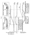
- Fig. 5 and Fig. 6 show the typical cornering scenario with deceleration/acceleration control by PGVC.
- Fig. 5 exemplarily shows the first stage of cornering: from closing to the curve to the steady state of cornering.
- the curvature of preview point ( ⁇ pv) increases before the vehicle starts turning ( Fig. 5 , section A).
- ⁇ pv increases and Pre-cornering deceleration command (Gxt_pv) is calculated based on ⁇ p (dash line).
- Gxt_GVC G-Vectoring deceleration command
- the deceleration command by PGVC is calculated by combining Gxt_pv and Gxt_GVC as shown in Fig. 5 (solid line).
- PGVC can decelerate the vehicle during the first stage of cornering.
- Fig. 6 exemplarily shows the last stage of cornering: from the steady state to the end of the curve. While the curvature of preview point ( ⁇ pv) is constant, PGVC gives no acceleration/ deceleration (keep the constant speed) ( Fig. 6 C ). When ⁇ pv starts decreasing and ⁇ pv becomes minus, cornering acceleration command (Gxt_pv) is calculated based on ⁇ p (dash line) ( Fig. 6 , section D). At the end of cornering, lateral-acceleration (Gy) starts decreasing, and G-Vectoring acceleration command (Gxt_GVC) is calculated based on lateral jerk information (dash-dot line) ( Fig. 6 , section E). The acceleration command by PGVC can be calculated by combining Gxt_pv and Gxt_GVC as shown in Fig. 6 (solid line). As the result, PGVC can accelerate the vehicle with the decreasing distance from the end of the curve.
- Fig. 7 exemplarily shows the two-cornering course to compare Gxt_PGVC with the driver's acceleration/deceleration behavior.
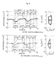
- Fig. 8 shows the comparison of longitudinal-acceleration caused by skilled driver ( Fig. 8 (a) ) and calculation result of PGVC command (Gxt_PGVC) ( Fig. 8 (b) ) at 80 km/h as initial speed (V0): left side shows the change of longitudinal- and lateral- acceleration (Gx, Gy), and right side shows "g-g" diagram.
- PGVC command (Gxt_PGVC) is calculated based on Equations (1) and (3) above using the curvature data calculated from target line shown in Fig. 7 , measured data of vehicle speed and lateral-acceleration by driving tests.
- lateral-acceleration (Gy)
- changes to plus for curve A and minus for curve B, and each lateral-acceleration change has three phases: increasing phase (phase (1)), steady state phase (phase (2)) and decreasing phase (phase (3)).
- the driver controls acceleration/deceleration depends on the lateral-acceleration changes; starts decelerating the vehicle ( Fig. 8 "decel.") before the phase (1) starts and finishes it when the phase (1) finishes.
- Fig. 9 exemplarily shows the block diagram of longitudinal-acceleration control system.
- ACC and PGVC are dealt as an independent function to replace/add/remove the functions easily.
- the combination block 130 is set combine the longitudinal-acceleration command of ACC (Gxt_ACC) and PGVC (Gxt_PGVC).
- the combination block 130 calculates the longitudinal-acceleration command (Gxt) and send it to the controller(s) 200 which controls the actuators for acceleration/deceleration of the vehicle (or it may send the longitudinal-acceleration command (Gxt) directly to actuators in other embodiments).
- the control system according to Fig. 9 comprises a longitudinal acceleration controller 100 (embodying a longitudinal acceleration control means) comprising an ACC block 110 (embodying a second longitudinal acceleration target value determining means), a PGVC block 120 (embodying a first longitudinal acceleration target value determining means), and a combination block 130 (embodying a third longitudinal acceleration target value determining means).
- a longitudinal acceleration controller 100 embodying a longitudinal acceleration control means
- ACC block 110 embodying a second longitudinal acceleration target value determining means
- PGVC block 120 embodying a first longitudinal acceleration target value determining means
- a combination block 130 embodying a third longitudinal acceleration target value determining means
- the combination block 130 receives the respective control commands (target values) Gxt_ACC and Gxt_PGVC from the ACC block 110 and the PGVC block 120, respectively, and determines based on Gxt_ACC and Gxt_PGVC the final command target value Gxt to be output to the actuator controller(s) 200 (or directly to actuators) for control of the longitudinal acceleration of the controlled vehicle based on the calculated target value Gxt.
- the system further comprises vehicle dynamics information detection devices 210, curvature detection devices 220, a driver input switch 230 and an obstacle detection device 240.
- a driver input switch 230 may be adapted to allow a user to select parameter settings of the PGVC parameters which can be input as driver input information to the PGVC block 120.
- vehicle dynamics information detection devices 210 such as sensors including speed sensor, accelerometer, gyro-senor, steering wheel angle sensor etc.
- vehicle dynamics information such as sensors including speed sensor, accelerometer, gyro-senor, steering wheel angle sensor etc.
- vehicle dynamics information vehicle dynamics information
- vehicle dynamics information such as vehicle speed, steering wheel angle, lateral and/or longitudinal acceleration acting on the controlled vehicle etc.
- the vehicle dynamics information is provided to the PGVC block 120.
- curvature information (such as map data and/or a curvature at a preview point determined based on map data) is provided from a curvature detection device 220 to the PGVC block 120 embodying the longitudinal acceleration target value determining means.
- the obstacle detection device 240 may receive data from the proceeding vehicle indicating a position, speed, lateral acceleration, and/or longitudinal acceleration acting on the proceeding vehicle, e.g. via a communication protocol.
- the obstacle detection device 240 may comprise sensors (such as camera, radar, sonar etc.) for determining a relative position and/or speed of the proceeding vehicle.
- information from the vehicle dynamics information detection devices 210, the curvature detection devices 220, the driver input switch 230 and/or the obstacle detection device 240 may also be provided to the combination block 130 for calculation weighting factors as described below.
- Gxt_ACC and Gxt_PGVC As a finally output target value Gxt, it would be possible to make Gxt by switching Gxt_ACC and Gxt_PGVC depending on the driving scene (following the proceeding vehicle, driving on the straight road, cornering etc.).
- all driving pattern and scene should be considered including complex scene and it would make the combination block complicated.
- Gxt may change discontinuously from one to the other by switching which would provide discomfort to the driver and may reduce safety.
- Gxt_ACC and Gxt_PGVC are selected as Gxt; deceleration command of Gxt_ACC or Gxt_PGVC, which is important value to keep the safe driving condition, has a priority to be a Gxt. Therefore, select-minimum method is highly useful from the aspects of safety.
- this method may not always work optimally, because the acceleration command of Gxt_ACC/Gxt_PGVC is not activated in some scenarios.
- This limited acceleration control might give the discomfort to the driver.
- Gxt_ACC can be set to a small value to avoid the unexpected acceleration during cornering until lateral-acceleration or steering angle becomes enough small. This function of ACC is necessary to keep safety when no curvature information is available.
- this deceleration control of ACC will be always selected during cornering and the acceleration command of Gxt_PGVC will not be activated, even though it is expected acceleration by drivers.
- Fig. 10 shows exemplary weighting functions based on ⁇ V tgt , ⁇ D, ⁇ V vpv and Gy_est.
- the weighting functions are set to increase the priority of Gxt_PGVC with increasing each values ( ⁇ V tgt , ⁇ D, ⁇ V vpv and Gy_est):
- Gxt_ACC is activated on a priority basis in the case vehicle speed close to/bigger than target speed, or the distance from the proceeding vehicle becomes smaller;
- Gxt_PGVC is activated on a priority basis in the case the estimated lateral-acceleration becomes bigger.
- the values of weighting factors can be determined as kW( ⁇ V tgt ), kW( ⁇ D), kW( ⁇ V vpv ), and kW(Gy_est) based on the weighting functions.
- the final combined longitudinal acceleration control target value G xt can be output to actuators as a command value for the actual longitudinal acceleration control of the controlled vehicle.
- Fig. 11 exemplarily shows the combination block with select-minimum method and weighting functions.
- the present invention is not limited to the use of all four weighting functions, and only one or more of the weighting functions functions kW( ⁇ V tgt ), kW( ⁇ D), kW( ⁇ V vpv ), and kW(Gy_est) can be used.
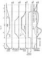
- Fig. 12 exemplarily shows the typical cornering scenario without any proceeding vehicle.
- ACC calculates the acceleration command (Gxt_ACC) to achieve the target speed (See Fig. 12 , sections A, B, D).
- Gxt_ACC (dash line in longitudinal-acceleration graph) is given high priority and selected as Gxt (solid line in longitudinal-acceleration graph), even though Gxt_PGVC (dot line in longitudinal-acceleration graph) is smaller than Gxt_ACC (See Fig. 12 , sections A, D).
- Gxt_PGVC With increasing of Gy_est, the priority of Gxt_PGVC increases and deceleration control of PGVC is selected by select-minimum method (See Fig. 12 , section B). After that, acceleration command Gxt_PGVC is selected as Gxt during cornering, because the increase of ⁇ Vtgt and Gy_est gives higher priority to Gxt_PGVC than Gxt_ACC (even though Gxt_ACC is smaller than Gxt_PGVC) (See Fig. 12 , section C). If only select-minimum method is used to make Gxt (dot line in longitudinal-acceleration graph), acceleration command of Gxt_ACC in Fig. 12 , section A, D and Gxt_PGVC in Fig.
- section C would not be selected as Gxt and the vehicle would not be accelerated.
- ⁇ D is used to change the priority of Gxt_ACC in addition to ⁇ V and Gy_est shown in Fig. 12 ; the decrease of ⁇ D increases the priority of Gxt_ACC.
- Fig. 13 exemplarily shows the cornering scenario with a proceeding vehicle.
- ⁇ D decreases, it increases the priority of Gxt_ACC and deceleration control of ACC to control the distance from the proceeding vehicle is selected (See Fig. 13 , section E).
- Fig. 14 exemplarily shows the system outline to control the longitudinal acceleration by ACC combined with PGVC.
- the control system comprises a longitudinal acceleration control unit 1 (e.g. realized as shown in Fig. 9 or Fig. 15 below), an accelerometer 2, a gyro-sensor 3, a steering wheel 4, a steering wheel angle sensor 5, an obstacle detect device 6, a tire 7, a vehicle 8, a curve-detect device 9, a brake control unit 10, a brake actuator 11, a drive-torque control unit 12, a drive-torque actuator 13 and a communication bus line 14.
- a longitudinal acceleration control unit 1 e.g. realized as shown in Fig. 9 or Fig. 15 below
- an accelerometer 2 e.g. realized as shown in Fig. 9 or Fig. 15 below
- a gyro-sensor 3 e.g. realized as shown in Fig. 9 or Fig. 15 below
- an accelerometer 2 e.g. realized as shown in Fig. 9 or Fig. 15 below
- Fig. 15 exemplarily shows another structure of longitudinal acceleration control system according to another embodiment of the present invention.
- an ACC control unit/block 300, a PGVC control unit/block 400 and the combination block 130 are implemented in different controllers 300, 400 and 100.
- other combination patterns are also available (e.g. distance sensor and ACC are implemented in the same controller, PGVC and combination block are implemented in the same controller, etc.).
- the control system according to Fig. 15 comprises a longitudinal acceleration controller 100 (embodying a longitudinal acceleration control means) comprising the combination block 130 (embodying a third longitudinal acceleration target value determining means).
- a longitudinal acceleration controller 100 embodying a longitudinal acceleration control means
- the combination block 130 embodying a third longitudinal acceleration target value determining means.
- Separate controllers exemplarily respectively include the PGVC block (PGVC controller 400, e.g. embodying a first longitudinal acceleration target value determining means), and the ACC block (ACC controller 300, e.g. embodying a second longitudinal acceleration target value determining means).
- the combination block 130 receives the respective control commands (target values) Gxt_ACC and Gxt_PGVC from the ACC controller 300 and the PGVC controller 400, respectively, and determines based on Gxt_ACC and Gxt_PGVC the final command target value Gxt to be output to the actuator controller(s) 200 (or directly to actuators) for control of the longitudinal acceleration of the controlled vehicle based on the calculated target value Gxt.
- weighting factors may be considered for adjusting the target values Gxt_ACC and Gxt_PGVC. This adjustment may be performed in the ACC controller 300 and the PGVC controller 400, or, more preferably, in the combination block 130.
Landscapes
- Engineering & Computer Science (AREA)
- Automation & Control Theory (AREA)
- Transportation (AREA)
- Mechanical Engineering (AREA)
- Physics & Mathematics (AREA)
- General Physics & Mathematics (AREA)
- Control Of Driving Devices And Active Controlling Of Vehicle (AREA)
- Controls For Constant Speed Travelling (AREA)
Priority Applications (4)
| Application Number | Priority Date | Filing Date | Title |
|---|---|---|---|
| EP13186774.9A EP2853457B1 (fr) | 2013-09-30 | 2013-09-30 | Procédé et appareil permettant de mettre en oeuvre une aide à la conduite |
| US14/166,966 US9043116B2 (en) | 2013-09-30 | 2014-01-29 | Method and apparatus for performing driving assistance |
| CN201410049903.9A CN104512405B (zh) | 2013-09-30 | 2014-02-13 | 用于执行驾驶辅助的方法和装置 |
| JP2014152742A JP6333655B2 (ja) | 2013-09-30 | 2014-07-28 | 車両の運転補助を行うための方法及び装置 |
Applications Claiming Priority (1)
| Application Number | Priority Date | Filing Date | Title |
|---|---|---|---|
| EP13186774.9A EP2853457B1 (fr) | 2013-09-30 | 2013-09-30 | Procédé et appareil permettant de mettre en oeuvre une aide à la conduite |
Publications (2)
| Publication Number | Publication Date |
|---|---|
| EP2853457A1 true EP2853457A1 (fr) | 2015-04-01 |
| EP2853457B1 EP2853457B1 (fr) | 2019-11-27 |
Family
ID=49253214
Family Applications (1)
| Application Number | Title | Priority Date | Filing Date |
|---|---|---|---|
| EP13186774.9A Active EP2853457B1 (fr) | 2013-09-30 | 2013-09-30 | Procédé et appareil permettant de mettre en oeuvre une aide à la conduite |
Country Status (4)
| Country | Link |
|---|---|
| US (1) | US9043116B2 (fr) |
| EP (1) | EP2853457B1 (fr) |
| JP (1) | JP6333655B2 (fr) |
| CN (1) | CN104512405B (fr) |
Cited By (5)
| Publication number | Priority date | Publication date | Assignee | Title |
|---|---|---|---|---|
| WO2020093357A1 (fr) * | 2018-11-07 | 2020-05-14 | Beijing Didi Infinity Technology And Development Co., Ltd. | Systèmes et procédés de prédiction de vitesse |
| WO2020104738A1 (fr) * | 2018-11-23 | 2020-05-28 | Psa Automobiles Sa | Régulation de la vitesse d'un véhicule en virage en fonction de la consigne de vitesse |
| EP4039556A1 (fr) * | 2021-02-09 | 2022-08-10 | Aptiv Technologies Limited | Commande d'accélération latérale pour conduite autonome |
| US11794776B2 (en) | 2021-02-09 | 2023-10-24 | Aptiv Technologies Limited | Trajectory validation for autonomous driving |
| US12263840B2 (en) | 2021-03-26 | 2025-04-01 | Aptiv Technologies AG | Longitudinal acceleration control for autonomous driving |
Families Citing this family (45)
| Publication number | Priority date | Publication date | Assignee | Title |
|---|---|---|---|---|
| GB2511867B (en) * | 2013-03-15 | 2016-07-13 | Jaguar Land Rover Ltd | Vehicle speed control system and method |
| EP2848488B2 (fr) * | 2013-09-12 | 2022-04-13 | Volvo Car Corporation | Procédé et agencement pour avertissement de transfert de commande dans un véhicule possédant des capacités de conduite autonome |
| US11348053B2 (en) * | 2015-05-20 | 2022-05-31 | Continental Automotive Systems, Inc. | Generating predictive information associated with vehicle products/services |
| JP6207553B2 (ja) * | 2015-07-16 | 2017-10-04 | 本田技研工業株式会社 | 運転支援装置、運転支援方法 |
| JP6408971B2 (ja) * | 2015-09-29 | 2018-10-17 | 本田技研工業株式会社 | 運転者の特性及び技量に応じた支援を行う運転支援装置 |
| CN105182342B (zh) * | 2015-09-29 | 2018-11-09 | 长安大学 | 一种颠簸路面车辆雷达目标位置的追踪装置及追踪方法 |
| JP6252992B2 (ja) | 2015-11-06 | 2017-12-27 | マツダ株式会社 | 車両用挙動制御装置 |
| JP6198181B2 (ja) | 2015-11-06 | 2017-09-20 | マツダ株式会社 | 車両用挙動制御装置 |
| JP6194940B2 (ja) | 2015-11-06 | 2017-09-13 | マツダ株式会社 | 車両用挙動制御装置 |
| JP6252993B2 (ja) | 2015-11-06 | 2017-12-27 | マツダ株式会社 | 車両用挙動制御装置 |
| JP6252994B2 (ja) | 2015-12-22 | 2017-12-27 | マツダ株式会社 | 車両用挙動制御装置 |
| JP6327244B2 (ja) * | 2015-12-25 | 2018-05-23 | トヨタ自動車株式会社 | 車両制御装置 |
| DE102016204136B4 (de) * | 2016-03-14 | 2018-07-12 | Ford Global Technologies, Llc | Verfahren und Vorrichtung zur automatisierten Längsbewegungssteuerung eines Kraftfahrzeugs |
| JP6604894B2 (ja) * | 2016-04-12 | 2019-11-13 | 日立オートモティブシステムズ株式会社 | 車両制御装置及び方法 |
| CN105946565A (zh) * | 2016-05-27 | 2016-09-21 | 北京理工大学 | 一种智能汽车底层纵向控制系统 |
| JP6213904B1 (ja) | 2016-06-30 | 2017-10-18 | マツダ株式会社 | 車両用挙動制御装置 |
| CN106114491B (zh) * | 2016-08-03 | 2019-01-01 | 奇瑞汽车股份有限公司 | 一种辅助驾驶方法、辅助驾驶系统及汽车 |
| JP6764312B2 (ja) * | 2016-10-19 | 2020-09-30 | 日立オートモティブシステムズ株式会社 | 車両運動制御装置、車両運動制御方法、車両運動制御プログラム |
| CN106740868B (zh) * | 2016-12-30 | 2019-03-29 | 东软集团股份有限公司 | 一种车速规划的方法、装置和设备 |
| US10703359B2 (en) * | 2017-01-27 | 2020-07-07 | Ford Global Technologies, Llc | Controlling vehicle orientation |
| DE102017212355B4 (de) * | 2017-07-19 | 2019-12-24 | Volkswagen Aktiengesellschaft | Verfahren zur Erkennung und zur Charakterisierung eines Fahrverhaltens eines Fahrers oder eines Autopiloten in einem Kraftfahrzeug, Steuereinheit und Kraftfahrzeug |
| JP6814710B2 (ja) * | 2017-08-10 | 2021-01-20 | 日立オートモティブシステムズ株式会社 | 車両運動制御装置及びその方法、並びに、目標軌道生成装置及びその方法 |
| CN107804322B (zh) * | 2017-09-18 | 2019-12-13 | 众泰新能源汽车有限公司 | 一种纯电动汽车整车控制器的自适应巡航控制方法 |
| CN109923489B (zh) * | 2017-10-12 | 2022-04-05 | 北京航迹科技有限公司 | 用于制动控制的系统和方法 |
| CN107856669A (zh) * | 2017-11-01 | 2018-03-30 | 合肥创宇新能源科技有限公司 | 基于跟随工况适应策略的acc控制方法 |
| JP6976142B2 (ja) * | 2017-11-09 | 2021-12-08 | 日立Astemo株式会社 | 車両運動制御装置、その方法、そのプログラム、及びそのシステム、並びに、目標軌道生成装置、その方法、そのプログラム、及びそのシステム |
| JP6521491B1 (ja) * | 2017-12-01 | 2019-05-29 | マツダ株式会社 | 車両の制御装置 |
| CN108466615A (zh) * | 2018-03-16 | 2018-08-31 | 中国农业大学 | 一种车辆主动极限态稳定性控制系统 |
| JP7011961B2 (ja) * | 2018-03-22 | 2022-02-10 | 日立Astemo株式会社 | 車両運動制御装置、車両運動制御方法、及び車両運動制御システム |
| CN109050531B (zh) * | 2018-07-27 | 2020-11-03 | 吉利汽车研究院(宁波)有限公司 | 一种巡航车速控制装置及方法 |
| JP7124561B2 (ja) * | 2018-08-28 | 2022-08-24 | 株式会社デンソー | 旋回制御装置 |
| JP7052677B2 (ja) * | 2018-11-01 | 2022-04-12 | トヨタ自動車株式会社 | 車両制御装置 |
| CN111267853B (zh) * | 2018-12-03 | 2021-06-18 | 广州汽车集团股份有限公司 | 一种自适应车辆弯道辅助控制方法、装置、计算机设备和存储介质 |
| WO2021039457A1 (fr) * | 2019-08-29 | 2021-03-04 | ソニー株式会社 | Corps mobile, dispositif de traitement d'informations, et procédé de traitement d'informations |
| CN110543193B (zh) * | 2019-08-30 | 2022-04-15 | 中国人民解放军国防科技大学 | 一种用于指向机构的在线加减速控制方法、系统及介质 |
| DE102020204082A1 (de) * | 2019-10-11 | 2021-04-15 | Robert Bosch Gesellschaft mit beschränkter Haftung | Verfahren zum Betreiben eines Fahrerassistenzsystems eines Fahrzeugs in einem Unterstützungsmodus und Fahrerassistenzsystem |
| JP7230795B2 (ja) | 2019-12-25 | 2023-03-01 | トヨタ自動車株式会社 | 車両制御装置 |
| JP7200976B2 (ja) * | 2020-05-12 | 2023-01-10 | 株式会社デンソー | ステアリング制御装置 |
| US12344248B2 (en) | 2020-08-20 | 2025-07-01 | Nissan Motor Co., Ltd. | Method and device for controlling vehicle acceleration on a curved road using curve information |
| JP7649122B2 (ja) * | 2020-09-30 | 2025-03-19 | 株式会社Subaru | 走行制御装置 |
| KR20220091076A (ko) * | 2020-12-23 | 2022-06-30 | 현대자동차주식회사 | 차량 및 그 제어방법 |
| US12252127B2 (en) * | 2022-04-19 | 2025-03-18 | Aptiv Technologies AG | Dynamically calculating lane change trajectories |
| GB202219846D0 (en) * | 2022-12-30 | 2023-02-15 | Five Ai Ltd | Controlling speed of an autonomous vehicle |
| CN115892005B (zh) * | 2023-01-28 | 2025-08-08 | 宁波路特斯机器人有限公司 | 自动驾驶车辆的纵向轨迹跟踪方法、控制器及存储介质 |
| US20260109358A1 (en) * | 2024-10-21 | 2026-04-23 | GM Global Technology Operations LLC | Motion control system determining a longitudinal acceleration command for a vehicle |
Citations (6)
| Publication number | Priority date | Publication date | Assignee | Title |
|---|---|---|---|---|
| EP0813987A2 (fr) * | 1996-06-20 | 1997-12-29 | Volkswagen Aktiengesellschaft | Procédé de commande de distance entre un véhicule et d'autres objets |
| US20070106445A1 (en) * | 2005-11-07 | 2007-05-10 | Nissan Motor Co., Ltd. | Deceleration controller for vehicle |
| EP1834855A1 (fr) * | 2005-03-23 | 2007-09-19 | Toyota Jidosha Kabushiki Kaisha | Dispositif de commande de course pour vehicule |
| EP1992537A2 (fr) | 2007-05-18 | 2008-11-19 | Hitachi, Ltd. | Unité de commande de mouvement pour un véhicule en fonction d'information sur la variation d'accélération |
| DE102010055373A1 (de) * | 2010-12-21 | 2012-06-21 | Daimler Ag | Verfahren zur Regelung einer Längsdynamik eines Kraftfahrzeugs und Kraftfahrzeug, in dem das Verfahren angewendet wird |
| EP2492160A1 (fr) * | 2009-10-23 | 2012-08-29 | Hitachi Automotive Systems, Ltd. | Unite de commande de mouvement de vehicule |
Family Cites Families (6)
| Publication number | Priority date | Publication date | Assignee | Title |
|---|---|---|---|---|
| JP5143103B2 (ja) * | 2009-09-30 | 2013-02-13 | 日立オートモティブシステムズ株式会社 | 車両の運動制御装置 |
| JP4990384B2 (ja) | 2010-06-21 | 2012-08-01 | 株式会社日立製作所 | 加加速度情報を用いた車両の運動制御方法 |
| JP5378318B2 (ja) | 2010-07-30 | 2013-12-25 | 日立オートモティブシステムズ株式会社 | 車両運動制御装置 |
| JP5127917B2 (ja) * | 2010-12-13 | 2013-01-23 | 日立オートモティブシステムズ株式会社 | 車両制御装置 |
| JP5417386B2 (ja) | 2011-07-01 | 2014-02-12 | 日立オートモティブシステムズ株式会社 | 車両運動制御装置 |
| JP5559833B2 (ja) | 2012-04-27 | 2014-07-23 | 株式会社日立製作所 | 加加速度情報を用いた車両の運動制御装置および方法 |
-
2013
- 2013-09-30 EP EP13186774.9A patent/EP2853457B1/fr active Active
-
2014
- 2014-01-29 US US14/166,966 patent/US9043116B2/en active Active
- 2014-02-13 CN CN201410049903.9A patent/CN104512405B/zh active Active
- 2014-07-28 JP JP2014152742A patent/JP6333655B2/ja active Active
Patent Citations (6)
| Publication number | Priority date | Publication date | Assignee | Title |
|---|---|---|---|---|
| EP0813987A2 (fr) * | 1996-06-20 | 1997-12-29 | Volkswagen Aktiengesellschaft | Procédé de commande de distance entre un véhicule et d'autres objets |
| EP1834855A1 (fr) * | 2005-03-23 | 2007-09-19 | Toyota Jidosha Kabushiki Kaisha | Dispositif de commande de course pour vehicule |
| US20070106445A1 (en) * | 2005-11-07 | 2007-05-10 | Nissan Motor Co., Ltd. | Deceleration controller for vehicle |
| EP1992537A2 (fr) | 2007-05-18 | 2008-11-19 | Hitachi, Ltd. | Unité de commande de mouvement pour un véhicule en fonction d'information sur la variation d'accélération |
| EP2492160A1 (fr) * | 2009-10-23 | 2012-08-29 | Hitachi Automotive Systems, Ltd. | Unite de commande de mouvement de vehicule |
| DE102010055373A1 (de) * | 2010-12-21 | 2012-06-21 | Daimler Ag | Verfahren zur Regelung einer Längsdynamik eines Kraftfahrzeugs und Kraftfahrzeug, in dem das Verfahren angewendet wird |
Cited By (9)
| Publication number | Priority date | Publication date | Assignee | Title |
|---|---|---|---|---|
| WO2020093357A1 (fr) * | 2018-11-07 | 2020-05-14 | Beijing Didi Infinity Technology And Development Co., Ltd. | Systèmes et procédés de prédiction de vitesse |
| US11004335B2 (en) | 2018-11-07 | 2021-05-11 | Beijing Didi Infinity Technology And Development Co., Ltd. | Systems and methods for speed prediction |
| WO2020104738A1 (fr) * | 2018-11-23 | 2020-05-28 | Psa Automobiles Sa | Régulation de la vitesse d'un véhicule en virage en fonction de la consigne de vitesse |
| FR3088882A1 (fr) * | 2018-11-23 | 2020-05-29 | Psa Automobiles Sa | Régulation de la vitesse d’un véhicule en virage en fonction de la consigne de vitesse |
| US11827218B2 (en) | 2018-11-23 | 2023-11-28 | Psa Automobiles Sa | Control of the speed of a vehicle when cornering in accordance with the speed setpoint |
| EP4039556A1 (fr) * | 2021-02-09 | 2022-08-10 | Aptiv Technologies Limited | Commande d'accélération latérale pour conduite autonome |
| US11780461B2 (en) | 2021-02-09 | 2023-10-10 | Aptiv Technologies Limited | Lateral acceleration control for autonomous driving |
| US11794776B2 (en) | 2021-02-09 | 2023-10-24 | Aptiv Technologies Limited | Trajectory validation for autonomous driving |
| US12263840B2 (en) | 2021-03-26 | 2025-04-01 | Aptiv Technologies AG | Longitudinal acceleration control for autonomous driving |
Also Published As
| Publication number | Publication date |
|---|---|
| US20150094927A1 (en) | 2015-04-02 |
| JP2015067270A (ja) | 2015-04-13 |
| US9043116B2 (en) | 2015-05-26 |
| CN104512405B (zh) | 2017-05-10 |
| CN104512405A (zh) | 2015-04-15 |
| EP2853457B1 (fr) | 2019-11-27 |
| JP6333655B2 (ja) | 2018-05-30 |
Similar Documents
| Publication | Publication Date | Title |
|---|---|---|
| EP2853457B1 (fr) | Procédé et appareil permettant de mettre en oeuvre une aide à la conduite | |
| EP2853458B1 (fr) | Procédé et appareil permettant de mettre en oeuvre une aide à la conduite | |
| US9352747B2 (en) | Vehicle travel control system | |
| US9105190B2 (en) | Driving support system for a vehicle | |
| CN102126497B (zh) | 在超车过程期间辅助驾驶员的方法和装置 | |
| JP5127917B2 (ja) | 車両制御装置 | |
| EP2763120B1 (fr) | Système d'aide à la conduite d'un véhicule | |
| JP5871060B2 (ja) | 車両の運転支援システム、路面摩擦状態推定システム | |
| EP2712780B1 (fr) | Procédé et appareil permettant de mettre en oeuvre une aide à la conduite | |
| US20120277967A1 (en) | Device for executing preceding vehicle following driving control | |
| JPWO2017145555A1 (ja) | 走行制御装置及び走行制御システム | |
| EP2712782A1 (fr) | Procédé et appareil permettant de mettre en 'uvre une aide à la conduite | |
| CN105593089B (zh) | 车辆的行驶控制装置 | |
| EP4219257A1 (fr) | Procédé de commande de déplacement de véhicule et dispositif de commande de déplacement de véhicule | |
| JP4613124B2 (ja) | ナビ協調走行制御装置 | |
| JP2025076093A (ja) | 車両の運転支援装置 | |
| JP6177743B2 (ja) | 車両制御装置 |
Legal Events
| Date | Code | Title | Description |
|---|---|---|---|
| PUAI | Public reference made under article 153(3) epc to a published international application that has entered the european phase |
Free format text: ORIGINAL CODE: 0009012 |
|
| 17P | Request for examination filed |
Effective date: 20131021 |
|
| AK | Designated contracting states |
Kind code of ref document: A1 Designated state(s): AL AT BE BG CH CY CZ DE DK EE ES FI FR GB GR HR HU IE IS IT LI LT LU LV MC MK MT NL NO PL PT RO RS SE SI SK SM TR |
|
| AX | Request for extension of the european patent |
Extension state: BA ME |
|
| STAA | Information on the status of an ep patent application or granted ep patent |
Free format text: STATUS: EXAMINATION IS IN PROGRESS |
|
| 17Q | First examination report despatched |
Effective date: 20180817 |
|
| GRAP | Despatch of communication of intention to grant a patent |
Free format text: ORIGINAL CODE: EPIDOSNIGR1 |
|
| STAA | Information on the status of an ep patent application or granted ep patent |
Free format text: STATUS: GRANT OF PATENT IS INTENDED |
|
| RIC1 | Information provided on ipc code assigned before grant |
Ipc: B60W 30/18 20120101ALN20190312BHEP Ipc: B60W 30/02 20120101ALN20190312BHEP Ipc: B60W 50/00 20060101ALN20190312BHEP Ipc: B60W 30/14 20060101AFI20190312BHEP |
|
| INTG | Intention to grant announced |
Effective date: 20190411 |
|
| RIC1 | Information provided on ipc code assigned before grant |
Ipc: B60W 30/14 20060101AFI20190402BHEP Ipc: B60W 30/18 20120101ALN20190402BHEP Ipc: B60W 30/02 20120101ALN20190402BHEP Ipc: B60W 50/00 20060101ALN20190402BHEP |
|
| RIN1 | Information on inventor provided before grant (corrected) |
Inventor name: TAKAHASHI, JUNYA Inventor name: ALTMANNSHOFER, HEIKO Inventor name: YAMAKADO, MAKOTO Inventor name: KOJIMA, TAKAO |
|
| GRAS | Grant fee paid |
Free format text: ORIGINAL CODE: EPIDOSNIGR3 |
|
| GRAA | (expected) grant |
Free format text: ORIGINAL CODE: 0009210 |
|
| STAA | Information on the status of an ep patent application or granted ep patent |
Free format text: STATUS: THE PATENT HAS BEEN GRANTED |
|
| AK | Designated contracting states |
Kind code of ref document: B1 Designated state(s): AL AT BE BG CH CY CZ DE DK EE ES FI FR GB GR HR HU IE IS IT LI LT LU LV MC MK MT NL NO PL PT RO RS SE SI SK SM TR |
|
| REG | Reference to a national code |
Ref country code: GB Ref legal event code: FG4D |
|
| REG | Reference to a national code |
Ref country code: CH Ref legal event code: EP |
|
| REG | Reference to a national code |
Ref country code: DE Ref legal event code: R096 Ref document number: 602013063304 Country of ref document: DE |
|
| REG | Reference to a national code |
Ref country code: AT Ref legal event code: REF Ref document number: 1206328 Country of ref document: AT Kind code of ref document: T Effective date: 20191215 |
|
| REG | Reference to a national code |
Ref country code: IE Ref legal event code: FG4D |
|
| REG | Reference to a national code |
Ref country code: DE Ref legal event code: R082 Ref document number: 602013063304 Country of ref document: DE Representative=s name: MERH-IP MATIAS ERNY REICHL HOFFMANN PATENTANWA, DE Ref country code: DE Ref legal event code: R081 Ref document number: 602013063304 Country of ref document: DE Owner name: HITACHI ASTEMO, LTD., HITACHINAKA-SHI, JP Free format text: FORMER OWNER: HITACHI, LTD., TOKYO, JP Ref country code: DE Ref legal event code: R081 Ref document number: 602013063304 Country of ref document: DE Owner name: HITACHI AUTOMOTIVE SYSTEMS, LTD., HITACHINAKA-, JP Free format text: FORMER OWNER: HITACHI, LTD., TOKYO, JP |
|
| REG | Reference to a national code |
Ref country code: GB Ref legal event code: 732E Free format text: REGISTERED BETWEEN 20200220 AND 20200226 |
|
| REG | Reference to a national code |
Ref country code: NL Ref legal event code: MP Effective date: 20191127 |
|
| REG | Reference to a national code |
Ref country code: LT Ref legal event code: MG4D |
|
| PG25 | Lapsed in a contracting state [announced via postgrant information from national office to epo] |
Ref country code: ES Free format text: LAPSE BECAUSE OF FAILURE TO SUBMIT A TRANSLATION OF THE DESCRIPTION OR TO PAY THE FEE WITHIN THE PRESCRIBED TIME-LIMIT Effective date: 20191127 Ref country code: GR Free format text: LAPSE BECAUSE OF FAILURE TO SUBMIT A TRANSLATION OF THE DESCRIPTION OR TO PAY THE FEE WITHIN THE PRESCRIBED TIME-LIMIT Effective date: 20200228 Ref country code: LV Free format text: LAPSE BECAUSE OF FAILURE TO SUBMIT A TRANSLATION OF THE DESCRIPTION OR TO PAY THE FEE WITHIN THE PRESCRIBED TIME-LIMIT Effective date: 20191127 Ref country code: SE Free format text: LAPSE BECAUSE OF FAILURE TO SUBMIT A TRANSLATION OF THE DESCRIPTION OR TO PAY THE FEE WITHIN THE PRESCRIBED TIME-LIMIT Effective date: 20191127 Ref country code: NL Free format text: LAPSE BECAUSE OF FAILURE TO SUBMIT A TRANSLATION OF THE DESCRIPTION OR TO PAY THE FEE WITHIN THE PRESCRIBED TIME-LIMIT Effective date: 20191127 Ref country code: FI Free format text: LAPSE BECAUSE OF FAILURE TO SUBMIT A TRANSLATION OF THE DESCRIPTION OR TO PAY THE FEE WITHIN THE PRESCRIBED TIME-LIMIT Effective date: 20191127 Ref country code: BG Free format text: LAPSE BECAUSE OF FAILURE TO SUBMIT A TRANSLATION OF THE DESCRIPTION OR TO PAY THE FEE WITHIN THE PRESCRIBED TIME-LIMIT Effective date: 20200227 Ref country code: LT Free format text: LAPSE BECAUSE OF FAILURE TO SUBMIT A TRANSLATION OF THE DESCRIPTION OR TO PAY THE FEE WITHIN THE PRESCRIBED TIME-LIMIT Effective date: 20191127 Ref country code: NO Free format text: LAPSE BECAUSE OF FAILURE TO SUBMIT A TRANSLATION OF THE DESCRIPTION OR TO PAY THE FEE WITHIN THE PRESCRIBED TIME-LIMIT Effective date: 20200227 |
|
| PG25 | Lapsed in a contracting state [announced via postgrant information from national office to epo] |
Ref country code: IS Free format text: LAPSE BECAUSE OF FAILURE TO SUBMIT A TRANSLATION OF THE DESCRIPTION OR TO PAY THE FEE WITHIN THE PRESCRIBED TIME-LIMIT Effective date: 20200327 Ref country code: HR Free format text: LAPSE BECAUSE OF FAILURE TO SUBMIT A TRANSLATION OF THE DESCRIPTION OR TO PAY THE FEE WITHIN THE PRESCRIBED TIME-LIMIT Effective date: 20191127 Ref country code: RS Free format text: LAPSE BECAUSE OF FAILURE TO SUBMIT A TRANSLATION OF THE DESCRIPTION OR TO PAY THE FEE WITHIN THE PRESCRIBED TIME-LIMIT Effective date: 20191127 |
|
| PG25 | Lapsed in a contracting state [announced via postgrant information from national office to epo] |
Ref country code: AL Free format text: LAPSE BECAUSE OF FAILURE TO SUBMIT A TRANSLATION OF THE DESCRIPTION OR TO PAY THE FEE WITHIN THE PRESCRIBED TIME-LIMIT Effective date: 20191127 |
|
| PG25 | Lapsed in a contracting state [announced via postgrant information from national office to epo] |
Ref country code: RO Free format text: LAPSE BECAUSE OF FAILURE TO SUBMIT A TRANSLATION OF THE DESCRIPTION OR TO PAY THE FEE WITHIN THE PRESCRIBED TIME-LIMIT Effective date: 20191127 Ref country code: CZ Free format text: LAPSE BECAUSE OF FAILURE TO SUBMIT A TRANSLATION OF THE DESCRIPTION OR TO PAY THE FEE WITHIN THE PRESCRIBED TIME-LIMIT Effective date: 20191127 Ref country code: PT Free format text: LAPSE BECAUSE OF FAILURE TO SUBMIT A TRANSLATION OF THE DESCRIPTION OR TO PAY THE FEE WITHIN THE PRESCRIBED TIME-LIMIT Effective date: 20200419 Ref country code: EE Free format text: LAPSE BECAUSE OF FAILURE TO SUBMIT A TRANSLATION OF THE DESCRIPTION OR TO PAY THE FEE WITHIN THE PRESCRIBED TIME-LIMIT Effective date: 20191127 Ref country code: DK Free format text: LAPSE BECAUSE OF FAILURE TO SUBMIT A TRANSLATION OF THE DESCRIPTION OR TO PAY THE FEE WITHIN THE PRESCRIBED TIME-LIMIT Effective date: 20191127 |
|
| REG | Reference to a national code |
Ref country code: DE Ref legal event code: R097 Ref document number: 602013063304 Country of ref document: DE |
|
| PG25 | Lapsed in a contracting state [announced via postgrant information from national office to epo] |
Ref country code: SM Free format text: LAPSE BECAUSE OF FAILURE TO SUBMIT A TRANSLATION OF THE DESCRIPTION OR TO PAY THE FEE WITHIN THE PRESCRIBED TIME-LIMIT Effective date: 20191127 Ref country code: SK Free format text: LAPSE BECAUSE OF FAILURE TO SUBMIT A TRANSLATION OF THE DESCRIPTION OR TO PAY THE FEE WITHIN THE PRESCRIBED TIME-LIMIT Effective date: 20191127 |
|
| REG | Reference to a national code |
Ref country code: AT Ref legal event code: MK05 Ref document number: 1206328 Country of ref document: AT Kind code of ref document: T Effective date: 20191127 |
|
| PLBE | No opposition filed within time limit |
Free format text: ORIGINAL CODE: 0009261 |
|
| STAA | Information on the status of an ep patent application or granted ep patent |
Free format text: STATUS: NO OPPOSITION FILED WITHIN TIME LIMIT |
|
| 26N | No opposition filed |
Effective date: 20200828 |
|
| PG25 | Lapsed in a contracting state [announced via postgrant information from national office to epo] |
Ref country code: SI Free format text: LAPSE BECAUSE OF FAILURE TO SUBMIT A TRANSLATION OF THE DESCRIPTION OR TO PAY THE FEE WITHIN THE PRESCRIBED TIME-LIMIT Effective date: 20191127 Ref country code: PL Free format text: LAPSE BECAUSE OF FAILURE TO SUBMIT A TRANSLATION OF THE DESCRIPTION OR TO PAY THE FEE WITHIN THE PRESCRIBED TIME-LIMIT Effective date: 20191127 Ref country code: AT Free format text: LAPSE BECAUSE OF FAILURE TO SUBMIT A TRANSLATION OF THE DESCRIPTION OR TO PAY THE FEE WITHIN THE PRESCRIBED TIME-LIMIT Effective date: 20191127 |
|
| PG25 | Lapsed in a contracting state [announced via postgrant information from national office to epo] |
Ref country code: IT Free format text: LAPSE BECAUSE OF FAILURE TO SUBMIT A TRANSLATION OF THE DESCRIPTION OR TO PAY THE FEE WITHIN THE PRESCRIBED TIME-LIMIT Effective date: 20191127 |
|
| PG25 | Lapsed in a contracting state [announced via postgrant information from national office to epo] |
Ref country code: MC Free format text: LAPSE BECAUSE OF FAILURE TO SUBMIT A TRANSLATION OF THE DESCRIPTION OR TO PAY THE FEE WITHIN THE PRESCRIBED TIME-LIMIT Effective date: 20191127 |
|
| REG | Reference to a national code |
Ref country code: CH Ref legal event code: PL |
|
| REG | Reference to a national code |
Ref country code: BE Ref legal event code: MM Effective date: 20200930 |
|
| PG25 | Lapsed in a contracting state [announced via postgrant information from national office to epo] |
Ref country code: LU Free format text: LAPSE BECAUSE OF NON-PAYMENT OF DUE FEES Effective date: 20200930 |
|
| REG | Reference to a national code |
Ref country code: DE Ref legal event code: R081 Ref document number: 602013063304 Country of ref document: DE Owner name: HITACHI ASTEMO, LTD., HITACHINAKA-SHI, JP Free format text: FORMER OWNER: HITACHI AUTOMOTIVE SYSTEMS, LTD., HITACHINAKA-SHI, IBARAKI-KEN, JP |
|
| PG25 | Lapsed in a contracting state [announced via postgrant information from national office to epo] |
Ref country code: BE Free format text: LAPSE BECAUSE OF NON-PAYMENT OF DUE FEES Effective date: 20200930 Ref country code: CH Free format text: LAPSE BECAUSE OF NON-PAYMENT OF DUE FEES Effective date: 20200930 Ref country code: LI Free format text: LAPSE BECAUSE OF NON-PAYMENT OF DUE FEES Effective date: 20200930 Ref country code: IE Free format text: LAPSE BECAUSE OF NON-PAYMENT OF DUE FEES Effective date: 20200930 |
|
| PG25 | Lapsed in a contracting state [announced via postgrant information from national office to epo] |
Ref country code: TR Free format text: LAPSE BECAUSE OF FAILURE TO SUBMIT A TRANSLATION OF THE DESCRIPTION OR TO PAY THE FEE WITHIN THE PRESCRIBED TIME-LIMIT Effective date: 20191127 Ref country code: MT Free format text: LAPSE BECAUSE OF FAILURE TO SUBMIT A TRANSLATION OF THE DESCRIPTION OR TO PAY THE FEE WITHIN THE PRESCRIBED TIME-LIMIT Effective date: 20191127 Ref country code: CY Free format text: LAPSE BECAUSE OF FAILURE TO SUBMIT A TRANSLATION OF THE DESCRIPTION OR TO PAY THE FEE WITHIN THE PRESCRIBED TIME-LIMIT Effective date: 20191127 |
|
| PG25 | Lapsed in a contracting state [announced via postgrant information from national office to epo] |
Ref country code: MK Free format text: LAPSE BECAUSE OF FAILURE TO SUBMIT A TRANSLATION OF THE DESCRIPTION OR TO PAY THE FEE WITHIN THE PRESCRIBED TIME-LIMIT Effective date: 20191127 |
|
| PGFP | Annual fee paid to national office [announced via postgrant information from national office to epo] |
Ref country code: DE Payment date: 20250805 Year of fee payment: 13 |
|
| PGFP | Annual fee paid to national office [announced via postgrant information from national office to epo] |
Ref country code: GB Payment date: 20250807 Year of fee payment: 13 |
|
| PGFP | Annual fee paid to national office [announced via postgrant information from national office to epo] |
Ref country code: FR Payment date: 20250808 Year of fee payment: 13 |