EP2853512B1 - Dispositif pour relier un moyen de levage, tel qu'une grue, à un objet qui doit être soulevé - Google Patents
Dispositif pour relier un moyen de levage, tel qu'une grue, à un objet qui doit être soulevé Download PDFInfo
- Publication number
- EP2853512B1 EP2853512B1 EP14185937.1A EP14185937A EP2853512B1 EP 2853512 B1 EP2853512 B1 EP 2853512B1 EP 14185937 A EP14185937 A EP 14185937A EP 2853512 B1 EP2853512 B1 EP 2853512B1
- Authority
- EP
- European Patent Office
- Prior art keywords
- lifting
- main part
- guiding parts
- contact surface
- lifted
- Prior art date
- Legal status (The legal status is an assumption and is not a legal conclusion. Google has not performed a legal analysis and makes no representation as to the accuracy of the status listed.)
- Not-in-force
Links
Images


Classifications
-
- B—PERFORMING OPERATIONS; TRANSPORTING
- B66—HOISTING; LIFTING; HAULING
- B66C—CRANES; LOAD-ENGAGING ELEMENTS OR DEVICES FOR CRANES, CAPSTANS, WINCHES, OR TACKLES
- B66C1/00—Load-engaging elements or devices attached to lifting or lowering gear of cranes or adapted for connection therewith for transmitting lifting forces to articles or groups of articles
- B66C1/10—Load-engaging elements or devices attached to lifting or lowering gear of cranes or adapted for connection therewith for transmitting lifting forces to articles or groups of articles by mechanical means
- B66C1/62—Load-engaging elements or devices attached to lifting or lowering gear of cranes or adapted for connection therewith for transmitting lifting forces to articles or groups of articles by mechanical means comprising article-engaging members of a shape complementary to that of the articles to be handled
- B66C1/64—Load-engaging elements or devices attached to lifting or lowering gear of cranes or adapted for connection therewith for transmitting lifting forces to articles or groups of articles by mechanical means comprising article-engaging members of a shape complementary to that of the articles to be handled for T- or I-section beams or girders
-
- B—PERFORMING OPERATIONS; TRANSPORTING
- B66—HOISTING; LIFTING; HAULING
- B66C—CRANES; LOAD-ENGAGING ELEMENTS OR DEVICES FOR CRANES, CAPSTANS, WINCHES, OR TACKLES
- B66C1/00—Load-engaging elements or devices attached to lifting or lowering gear of cranes or adapted for connection therewith for transmitting lifting forces to articles or groups of articles
- B66C1/10—Load-engaging elements or devices attached to lifting or lowering gear of cranes or adapted for connection therewith for transmitting lifting forces to articles or groups of articles by mechanical means
- B66C1/12—Slings comprising chains, wires, ropes, or bands; Nets
- B66C1/16—Slings with load-engaging platforms or frameworks
Definitions
- the present invention relates to a device to connect a lifting appliance, such as a crane, to an object that shall be lifted.
- the device is especially suited for use together with lifting tools in the form of extended bodies of textile material, rope or wire, which is formed with hoops or hooks in at least one end, or as endless grommets.
- lifting tools are often used when one wants to lift objects that are not fitted with lifting lugs for a crane hook and are used to form the connection between the crane hook and the lifting lug.
- a hoop can comprise one or more straps, each of which stretches from one place on the object to the crane hook, or possibly to the crane hook via a spreader beam.
- a lifting block is known from US 4092038 that is adapted to encircle a tubular element on the structure to be lifted. Although, it is relatively easy to mount it can easily slide along the tubular element and the structure may therefore suddenly tilt viciously. This tilting may be fatal both to equipment and persons in the vicinity.
- stop means are arranged adjacent the lifting block. The stop means have to be welded to the structure. This welding may weaken the structure and has to be controlled and certified.
- the lifting block must also be adapted closely in diameter to the tubular element that it is placed around.
- JPH0444274U shows a lifting device for a pallet. Inclined notches are formed on the underside of the pallet, into which a tube can be positioned. Lifting straps can be attached to each end of the tubes.
- This device is only capable of lifting pallets that have been prepared with the inclined notches.
- the lifting must be done with the pallet in a completely horizontal position. If the centre of gravity of the load is outside the centre of the pallet, the pallet may become skewed and there is a great risk that the pallet will slide relative to the tubes. The result may be that the lifting straps slide off the tubes and the load falls down.
- this lifting device is not suitable for lifting objects with a centre of gravity away from the volumetric centre of the object or where the centre of gravity is unknown.
- US 3276808 shows a similar lifting device as JPH0444274U. Also here notches have been formed at the underside of the pallet. This device has substantially the same disadvantages as JPH0444274U.
- US 2721756 shows another lifting device similar to JPH0444274U and US 3276808 . This has substantially the same disadvantages as the above prior art.
- US 3519302 shows yet another lifting device for lifting pallets, which also have substantially the same drawbacks as JPH0444274U, US 3276808 and US 2721756 .
- JP2002362878 shows a lifting device for lifting the undercarriage of a belt driven vehicle.
- the device is specially formed to fit against the underside of the undercarriage.
- the device is not suitable for lifting other objects, such as portions of frameworks in the offshore industry.
- the invention has the aim of providing a device that makes it possible to connect a lifting tool with a large object in a safe and easy way. This is achieved by the features that are given in the subsequent claim 1.
- the lifting device is fitted quickly and simply and the time it takes, for example, to decommission an offshore structure is thereby considerably reduced. This also reduces the costs.
- the lifting forces are transferred as pressure forces only in the structure that is lifted. Thereby, any weaknesses in the structure material have less significance.
- the lifting device according to the invention has a contact surface against the structure which is large enough so that the lifting forces do not lead to essential, permanent, i.e. plastic, deformations in the lifting device.
- the main part is fitted at both ends with a trunnion-formed end comprising a groove with a generally circular cross section and an externally arranged thickening, as the groove is able to receive a hoop or a loop on a wire, and the thickening prevents the hoop or the wire from sliding out from the groove.
- the device can easily be connected with a hoop or a wire.
- the guiding parts have features for anchoring of a temporary fastening element to hold the device in place until the lifting forces are established. Thereby, the device can temporarily hang on to the object that shall be lifted until the lifting forces are connected and the lift has begun.
- the guiding parts are set up to reach over the beam or the strut, which the main part is placed on the underside of, and the guiding parts are fitted at their upper ends with fastening means for a hoop or other extended body.
- the fastening means comprises a hole through each of the guiding parts and a peg that is arranged to be led through the holes.
- a shackle can easily be connected to the device.
- the contact surface is formed by a plate that is located between the guiding parts. Thereby, a good contact surface is ensured against the object that shall be lifted. This gives a good distribution of forces.
- At least one support plate is connected at a right angle with the plate that forms the contact surface. This support plate transfers forces to the main part. Thereby, a good shoring up of the plate that makes up the contact surface and a good force transfer to the main part is ensured. Then, the plate that makes up the contact surface can advantageously have smaller dimensions.
- At least a part of the first contact surface comprises an end edge on a support plate that is arranged transverse to the main part.
- the device substantially comprises steel plates that are welded together and possibly a steel tube that forms the trunk of the main part, a device is provided that is both simple to produce and simple in its structure.
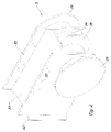
- Figure 1 shows a structure part 1 which is a part of a larger offshore structure that is about to be decommissioned.
- the structure part 1 hangs in a crane (not shown) via a crane hook 2 that can be placed on a crane vessel (not shown).
- a system of hoops 3 extends from the crane hook 2.
- These couple the crane hook 2 via a spreader beam 17 and hooks 4 to a device 5 according to the invention, which in the following will be called a lifting block, which together is set to lift the structure part 1.
- Figure 1a shows a detail of figure 1 around the lifting device 5.
- the lifting device 5 is arranged under an I-beam 26 in the structure part 1 and lies in a corner formed by the I-beam 26 and a strut 27.
- the strut 27 also has an I-beam form.
- the I-beam 26 has a flat underside against the lifting device 5 and the strut 27 also has a flat side against the lifting device 5.
- the lifting block 5 can be formed to lie against other types of beams than I-beams and also against struts with a round or oval cross section.
- the lifting block 5 stretches underneath the whole of the I-beam 26 and has, on either side, a trunnion-like projection 28 to receive a loop 30 at the end of a hoop.
- Figure 2 shows the lifting block 5 according to the invention in more detail in a first embodiment.
- the projection 28 has a disc 29 outermost and inside this there is a cylindrical section 31, which the loop 30 of the hoop 3 is set up to rest against.
- guiding plates 32 are arranged on each side. The guiding plates 32 are set up to be placed on the outside of the I-beam 26 and prevent the lifting block 32 from gliding sidewise with respect to this.
- a contact surface 33 is arranged between the guiding plates 32. This is set up to lie against the underside of the I-beam 26.
- the cylindrical section 31 is extended inside the guiding plates 32 and forms a continuous cylinder 34.
- a support plate 35 is arranged in parallel with and in the middle of the guiding plates 32.
- the edge 36 of the support plate 35 is set up to lie against the strut 27. Thereby, the lifting block transfers the lifting forces into the I-beam 26 and the strut 27.
- the guiding plates 32 are fitted with a number of holes 37 that are used to fasten temporarily the lifting block 5 to the I-beam 26 until the hoops are subjected to tension and the lifting block is held in place by the hoops alone.
- the temporary fastening to the I-beam can be made by threading bolts or pins through the holes 37 so that the lifting block 5 is hanging in the flange 38 of the I-beam 26 (see figure 1 a ).
- protrusions can also be arranged for the fastening of the straps.
- other ways to arrange a temporary fastening for the lifting block can also be imagined.
- the lifting block 5 is constructed by welding together a pipe 34 with the different plates 28, 32, 33 and 35. It can be made in different sizes adjusted to the different dimensions used for the I-beams 26.
- the lifting block 5 must be certified for offshore lifts, but this certification can be made in good time before use and it can be made on land.
- the pipe 34 has a dimension, which will tolerate with a good margin the forces to which it is subjected. As long as the hoop is taut (even with relatively limited tension), it will stay within the plate 28.
- the plate 28 is dimensioned so that the loop 30 must be opened relatively widely so that it is possible to thread it over the plate 28. The lift can therefore be carried out with the assurance that the loop 30 will not jump off the lifting block 5.
- the lifting block will transfer a part of the horizontal lifting forces into the lower flange of the beam 26 in the junction between the beam 26 and the strut 27.
- Figure 3 shows a second embodiment of the lifting block according to the invention. It is substantially similar to the embodiment in figure 2 apart from the guiding plates 32 being rotated with respect to the contact plate 33, so that the upper edge 39 (upper in the sense of uppermost in the figure) forms an angle with the contact plate 33. This rotated position ensures that the guiding plate 32 will extend outside both the I-beams in the structure that form the corner against which the lifting device shall lie. This embodiment is particularly favourable if the corner is made by two beams of the same width.
- the holes 37 are placed so that it is possible temporarily to fasten the lifting block 5 to the flanges on both the adjoining I-beams.
- Figure 4 shows a third embodiment of the lifting block 5, where the guiding plates 32 are extended with respect to the embodiment in figure 2 , so that they extend along a greater length of the I-beam.
- An arched plate 40 is arranged at the extended end of the guiding plates 32. This is set up to lie against a round strut on the structure that shall be lifted. The curvature of the plate 40 must be adapted to the different diameters on the round strut on the structure. Therefore, lifting blocks of different dimensions must be produced.
- Figure 5 shows a fourth embodiment of the lifting block 5 according to the invention.
- the guiding plates 32 are extended so that they stretch over the I-beam 26.
- the guiding plates 32 that also function as lifting plates are fitted at the upper end with holes 41 and a peg 42 that stretches between the holes 41.
- a lifting shackle 43 is fastened to the peg 42.
- a hoop is in turn fastened to the lifting shackle 43.
- the lifting block 5 in figure 5 is shown in more detail in the figures 6a and 6b.
- Figure 6a shows the lifting block seen in perspective from above.
- Figure 6b shows the lifting block 5 seen in perspective from below. From above and below means in this context in relation to the orientation that the lifting block has when in use.
- the lifting block 5 comprises a pipe part 44 that extends between the two guiding and lifting plates 32.
- a contact plate 33 also runs between the guiding and lifting plates 32.
- a support plate 35 that has a contact edge 36 is placed halfway between, and in parallel with, the guiding and lifting plates 32.
- a pair of stiffening plates 45 is arranged between the pipe part 44 and the contact plate 33. Both of these run between the guiding and lifting plates 32.
- the holes 41 in the upper end of the guiding and lifting plates 32 are also visible.
- the guiding and lifting plates 32 are fitted with holes 37 that can be used to fasten the lifting device temporarily to the I-beams 26 in the same way as for the earlier embodiment.
- the lifting device shall be placed in a corner between the beam 26 and the strut 27 that form an angle of about 45°.
- the contact edge 36 of the support plate 35 and the contact plate 33 form a corresponding angle so that they make good contact against both the I-beam 26 and the strut 27 in the corner. This is ensured by tightening the lifting tool 3 by lifting the crane hook 2.
- the lifting block 5 thereby automatically will be pulled into a correct position with the help of the guiding and lifting plates 32.
- the lifting plate 33 will transfer parts of the horizontal lifting forces in the lower flange of the beam 26 in the cross between the beam 26 and the strut 27.
- the peg 42 When the lifting block is placed in the corner between the I-beam 26 and the strut 27, the peg 42 is threaded through the hole 41 in one of the guiding and lifting plates 32, through the ears of the shackle 43 (the shackle 43 is threaded through the loop 30 of the hoop in advance) and further through the hole 41 in the other guiding and lifting plate 32. Thereafter, the peg 42 is secured in a way that is well known for lifting shackles.
- the hoops will be in safe engagement with the lifting blocks without having to be taut.
Landscapes
- Engineering & Computer Science (AREA)
- Mechanical Engineering (AREA)
- Load-Engaging Elements For Cranes (AREA)
Claims (11)
- Dispositif pour relier un appareil de levage à un objet qui doit être soulevé, le dispositif (5) comprenant une partie principale, ladite partie principale ayant une première surface de contact (33) qui est complémentaire d'un premier élément longitudinal (26) de l'objet (1) qui doit être soulevé quand ladite partie principale s'étend de manière sensiblement transversale par rapport au premier élément longitudinal (26), caractérisé en ce que ladite partie principale comporte une deuxième surface de contact (36) qui est complémentaire d'un deuxième élément (27) sur l'objet (1) qui doit être soulevé, lesdites surfaces de contact (33, 36) formant un angle fixe l'une par rapport à l'autre, ledit angle correspondant à l'angle entre les premier et deuxième éléments (26, 27), ladite partie principale étant configurée pour prendre le poids de l'objet par l'intermédiaire des première et deuxième surfaces de contact (33, 36), et en ce que chaque extrémité (29, 31) de la partie principale est pourvue d'accessoires de liaison pour un outil de levage, et en ce que le dispositif comprend en outre une paire de parties de guidage (32), qui sont agencées perpendiculairement à la partie principale, lesdites parties de guidage (32) étant agencées à une distance mutuelle légèrement supérieure à la largeur dudit premier élément (26).
- Dispositif selon la revendication 1, caractérisé en ce que les étendues des surfaces de contact (33, 36) sont adaptées au poids de l'objet (1) qui doit être soulevé de telle sorte que des déformations permanentes sont essentiellement évitées.
- Dispositif selon la revendication 1 ou 2, caractérisé en ce que lesdits accessoires de liaison sont des éléments d'extrémité en forme de tourillon (29, 31), comprenant une rainure (31) ayant une coupe transversale globalement circulaire et un épaississement externe (29), et de telle sorte que la rainure (31) est capable de recevoir un cercle ou une boucle sur un câble et l'épaississement (29) empêche le cercle ou le câble de glisser hors de la rainure (31).
- Dispositif selon l'une quelconque des revendications précédentes, caractérisé en ce que les parties de guidage (32) présentent des accessoires (37) pour l'ancrage d'un élément de fixation provisoire pour maintenir le dispositif en place jusqu'à ce que les forces de levage lui soient sont appliquées.
- Dispositif selon l'une quelconque des revendications précédentes, caractérisé en ce que les parties de guidage (32) ont une longueur pour passer par-dessus le premier élément (26) jusqu'au côté opposé du premier élément depuis la première surface de contact (33), et en ce que les parties de guidage (32) sont équipées, au niveau de leurs extrémités supérieures, de moyens de fixation (41, 42, 43) pour un cercle (30) ou câble de levage.
- Dispositif selon la revendication 5, caractérisé en ce que les moyens de fixation comprennent un trou (41) dans chacune des parties de guidage (32) et une cheville (42) qui s'insère dans les trous (41).
- Dispositif selon l'une quelconque des revendications précédentes, caractérisé en ce que la surface de contact (33) est formée par une plaque qui est placée entre les parties de guidage (32).
- Dispositif selon la revendication 7, caractérisé en ce qu'au moins une plaque de support (35) est reliée selon un angle droit à la plaque qui forme ladite première surface de contact (33).
- Dispositif selon l'une quelconque des revendications précédentes, caractérisé en ce qu'au moins une partie de ladite première surface de contact (36) comprend un bord d'extrémité sur une plaque de support (35) qui est agencée de manière transversale à la partie principale.
- Dispositif selon l'une des revendications précédentes, caractérisé en ce qu'il comprend sensiblement des plaques en acier qui sont soudées ensemble.
- Dispositif selon la revendication 10, caractérisé en ce qu'il comprend également un tuyau en acier (34) qui forme un tronc de la partie principale.
Applications Claiming Priority (1)
| Application Number | Priority Date | Filing Date | Title |
|---|---|---|---|
| NO20131289A NO338892B1 (no) | 2013-09-26 | 2013-09-26 | Anordning for å koble en løfteinnretning, slik som en kran, til en gjenstand som skal løftes |
Publications (2)
| Publication Number | Publication Date |
|---|---|
| EP2853512A1 EP2853512A1 (fr) | 2015-04-01 |
| EP2853512B1 true EP2853512B1 (fr) | 2016-07-13 |
Family
ID=51609963
Family Applications (1)
| Application Number | Title | Priority Date | Filing Date |
|---|---|---|---|
| EP14185937.1A Not-in-force EP2853512B1 (fr) | 2013-09-26 | 2014-09-23 | Dispositif pour relier un moyen de levage, tel qu'une grue, à un objet qui doit être soulevé |
Country Status (3)
| Country | Link |
|---|---|
| EP (1) | EP2853512B1 (fr) |
| DK (1) | DK2853512T3 (fr) |
| NO (1) | NO338892B1 (fr) |
Families Citing this family (1)
| Publication number | Priority date | Publication date | Assignee | Title |
|---|---|---|---|---|
| CN110259417B (zh) * | 2019-07-22 | 2023-12-12 | 广州海洋地质调查局 | 一种深海钻井采油树移运装置 |
Family Cites Families (12)
| Publication number | Priority date | Publication date | Assignee | Title |
|---|---|---|---|---|
| US2721756A (en) * | 1952-12-01 | 1955-10-25 | Markussen Markus | Cargo pallets |
| US3276808A (en) * | 1964-08-18 | 1966-10-04 | Anthony J Scaramuzzi | Supports for a nestable pallet |
| US3519302A (en) * | 1968-06-07 | 1970-07-07 | Sun Shipbuilding & Dry Dock Co | Pallet lifting device |
| US4092038A (en) * | 1977-02-16 | 1978-05-30 | Brown & Root, Inc. | Jacket with improved lifting means |
| JPS5447770U (fr) * | 1977-09-08 | 1979-04-03 | ||
| JPH0543018Y2 (fr) * | 1990-08-21 | 1993-10-28 | ||
| JPH0549780U (ja) * | 1991-12-13 | 1993-06-29 | 小野田エー・エル・シー株式会社 | パネル吊り上げ用受承部材 |
| JPH072377U (ja) * | 1993-06-16 | 1995-01-13 | ミサワホーム株式会社 | 建材の荷受方法および吊上治具 |
| US5735561A (en) * | 1996-08-26 | 1998-04-07 | Abl Boatlifts | Lift device for small watercraft |
| US5863085A (en) * | 1996-09-23 | 1999-01-26 | Versabar, Inc. | Spreader bar assembly |
| JP4510138B2 (ja) * | 2001-06-01 | 2010-07-21 | 日立建機株式会社 | サイドフレーム用吊り治具 |
| AU2007288160A1 (en) * | 2006-08-25 | 2008-02-28 | I & S Larard Pty Ltd | A lifting assembly |
-
2013
- 2013-09-26 NO NO20131289A patent/NO338892B1/no unknown
-
2014
- 2014-09-23 EP EP14185937.1A patent/EP2853512B1/fr not_active Not-in-force
- 2014-09-23 DK DK14185937.1T patent/DK2853512T3/en active
Also Published As
| Publication number | Publication date |
|---|---|
| EP2853512A1 (fr) | 2015-04-01 |
| NO20131289A1 (no) | 2015-03-27 |
| DK2853512T3 (en) | 2016-09-05 |
| NO338892B1 (no) | 2016-10-31 |
Similar Documents
| Publication | Publication Date | Title |
|---|---|---|
| US7017741B1 (en) | Method and apparatus for transporting pressurized gas canisters | |
| US5603544A (en) | Compression cap assembly for spreader pipe | |
| ZA200300319B (en) | Device for handling unit loads. | |
| WO2003093160A1 (fr) | Dispositif permettant l'expedition et le stockage d'elements allonges | |
| JP3782776B2 (ja) | ユニットロードを操作するためのデバイス | |
| US20030160468A1 (en) | Load supporting apparatus with integrated couplings for lifting | |
| JP7015250B2 (ja) | 昇降システム、およびこのような昇降システムのためのキャリア要素 | |
| EP2853512B1 (fr) | Dispositif pour relier un moyen de levage, tel qu'une grue, à un objet qui doit être soulevé | |
| US20200002137A1 (en) | Apparatus and method for carrying elongate construction elements | |
| AU2024278501B2 (en) | Lifting apparatus and method for hoisting a gyratory crusher spider | |
| CN108773768A (zh) | 一种大型h型钢柱的吊装工装及其吊装方法 | |
| US20020135189A1 (en) | Integrated lifting apparatus | |
| US20150052726A1 (en) | Safety Appliance for a Downhaul Weight | |
| KR20060035704A (ko) | 길이 가변형 와이어슬링 | |
| JP3204833U (ja) | 吊りピース付きコラム切梁 | |
| US20200156904A1 (en) | Lifting device | |
| CN203497919U (zh) | 直升机平台整体吊装装置 | |
| US20030079436A1 (en) | Lifting frame | |
| JPH08143267A (ja) | 吊り上げラグ付き長大物用スキッドおよびそれを利用した長大物の移送方法 | |
| KR20140003936U (ko) | H빔 운반용 지그 | |
| GB2040872A (en) | Sling engagement boss | |
| RU2751379C1 (ru) | Грузозахватное устройство | |
| CN202245829U (zh) | 吊装活塞缸的固定结构以及工程机械 | |
| CN211110608U (zh) | 一种重型卧式设备吊装装置 | |
| KR200283392Y1 (ko) | 기중기로 컨테이너를 운반하기 위한 아이 보울트 고정판설치 구조 |
Legal Events
| Date | Code | Title | Description |
|---|---|---|---|
| PUAI | Public reference made under article 153(3) epc to a published international application that has entered the european phase |
Free format text: ORIGINAL CODE: 0009012 |
|
| 17P | Request for examination filed |
Effective date: 20140923 |
|
| AK | Designated contracting states |
Kind code of ref document: A1 Designated state(s): AL AT BE BG CH CY CZ DE DK EE ES FI FR GB GR HR HU IE IS IT LI LT LU LV MC MK MT NL NO PL PT RO RS SE SI SK SM TR |
|
| AX | Request for extension of the european patent |
Extension state: BA ME |
|
| GRAP | Despatch of communication of intention to grant a patent |
Free format text: ORIGINAL CODE: EPIDOSNIGR1 |
|
| INTG | Intention to grant announced |
Effective date: 20160129 |
|
| GRAS | Grant fee paid |
Free format text: ORIGINAL CODE: EPIDOSNIGR3 |
|
| GRAP | Despatch of communication of intention to grant a patent |
Free format text: ORIGINAL CODE: EPIDOSNIGR1 |
|
| INTG | Intention to grant announced |
Effective date: 20160512 |
|
| GRAA | (expected) grant |
Free format text: ORIGINAL CODE: 0009210 |
|
| AK | Designated contracting states |
Kind code of ref document: B1 Designated state(s): AL AT BE BG CH CY CZ DE DK EE ES FI FR GB GR HR HU IE IS IT LI LT LU LV MC MK MT NL NO PL PT RO RS SE SI SK SM TR |
|
| REG | Reference to a national code |
Ref country code: GB Ref legal event code: FG4D |
|
| REG | Reference to a national code |
Ref country code: AT Ref legal event code: REF Ref document number: 812137 Country of ref document: AT Kind code of ref document: T Effective date: 20160715 Ref country code: CH Ref legal event code: EP |
|
| REG | Reference to a national code |
Ref country code: IE Ref legal event code: FG4D |
|
| REG | Reference to a national code |
Ref country code: DE Ref legal event code: R096 Ref document number: 602014002648 Country of ref document: DE |
|
| REG | Reference to a national code |
Ref country code: DK Ref legal event code: T3 Effective date: 20160830 |
|
| REG | Reference to a national code |
Ref country code: NL Ref legal event code: FP |
|
| REG | Reference to a national code |
Ref country code: LT Ref legal event code: MG4D |
|
| REG | Reference to a national code |
Ref country code: AT Ref legal event code: MK05 Ref document number: 812137 Country of ref document: AT Kind code of ref document: T Effective date: 20160713 |
|
| PG25 | Lapsed in a contracting state [announced via postgrant information from national office to epo] |
Ref country code: FI Free format text: LAPSE BECAUSE OF FAILURE TO SUBMIT A TRANSLATION OF THE DESCRIPTION OR TO PAY THE FEE WITHIN THE PRESCRIBED TIME-LIMIT Effective date: 20160713 Ref country code: IS Free format text: LAPSE BECAUSE OF FAILURE TO SUBMIT A TRANSLATION OF THE DESCRIPTION OR TO PAY THE FEE WITHIN THE PRESCRIBED TIME-LIMIT Effective date: 20161113 Ref country code: RS Free format text: LAPSE BECAUSE OF FAILURE TO SUBMIT A TRANSLATION OF THE DESCRIPTION OR TO PAY THE FEE WITHIN THE PRESCRIBED TIME-LIMIT Effective date: 20160713 Ref country code: IT Free format text: LAPSE BECAUSE OF FAILURE TO SUBMIT A TRANSLATION OF THE DESCRIPTION OR TO PAY THE FEE WITHIN THE PRESCRIBED TIME-LIMIT Effective date: 20160713 Ref country code: NO Free format text: LAPSE BECAUSE OF FAILURE TO SUBMIT A TRANSLATION OF THE DESCRIPTION OR TO PAY THE FEE WITHIN THE PRESCRIBED TIME-LIMIT Effective date: 20161013 Ref country code: LT Free format text: LAPSE BECAUSE OF FAILURE TO SUBMIT A TRANSLATION OF THE DESCRIPTION OR TO PAY THE FEE WITHIN THE PRESCRIBED TIME-LIMIT Effective date: 20160713 Ref country code: HR Free format text: LAPSE BECAUSE OF FAILURE TO SUBMIT A TRANSLATION OF THE DESCRIPTION OR TO PAY THE FEE WITHIN THE PRESCRIBED TIME-LIMIT Effective date: 20160713 |
|
| PG25 | Lapsed in a contracting state [announced via postgrant information from national office to epo] |
Ref country code: GR Free format text: LAPSE BECAUSE OF FAILURE TO SUBMIT A TRANSLATION OF THE DESCRIPTION OR TO PAY THE FEE WITHIN THE PRESCRIBED TIME-LIMIT Effective date: 20161014 Ref country code: LV Free format text: LAPSE BECAUSE OF FAILURE TO SUBMIT A TRANSLATION OF THE DESCRIPTION OR TO PAY THE FEE WITHIN THE PRESCRIBED TIME-LIMIT Effective date: 20160713 Ref country code: PT Free format text: LAPSE BECAUSE OF FAILURE TO SUBMIT A TRANSLATION OF THE DESCRIPTION OR TO PAY THE FEE WITHIN THE PRESCRIBED TIME-LIMIT Effective date: 20161114 Ref country code: SE Free format text: LAPSE BECAUSE OF FAILURE TO SUBMIT A TRANSLATION OF THE DESCRIPTION OR TO PAY THE FEE WITHIN THE PRESCRIBED TIME-LIMIT Effective date: 20160713 Ref country code: BE Free format text: LAPSE BECAUSE OF NON-PAYMENT OF DUE FEES Effective date: 20160713 Ref country code: AT Free format text: LAPSE BECAUSE OF FAILURE TO SUBMIT A TRANSLATION OF THE DESCRIPTION OR TO PAY THE FEE WITHIN THE PRESCRIBED TIME-LIMIT Effective date: 20160713 Ref country code: ES Free format text: LAPSE BECAUSE OF FAILURE TO SUBMIT A TRANSLATION OF THE DESCRIPTION OR TO PAY THE FEE WITHIN THE PRESCRIBED TIME-LIMIT Effective date: 20160713 Ref country code: PL Free format text: LAPSE BECAUSE OF FAILURE TO SUBMIT A TRANSLATION OF THE DESCRIPTION OR TO PAY THE FEE WITHIN THE PRESCRIBED TIME-LIMIT Effective date: 20160713 |
|
| REG | Reference to a national code |
Ref country code: DE Ref legal event code: R119 Ref document number: 602014002648 Country of ref document: DE |
|
| PG25 | Lapsed in a contracting state [announced via postgrant information from national office to epo] |
Ref country code: EE Free format text: LAPSE BECAUSE OF FAILURE TO SUBMIT A TRANSLATION OF THE DESCRIPTION OR TO PAY THE FEE WITHIN THE PRESCRIBED TIME-LIMIT Effective date: 20160713 Ref country code: RO Free format text: LAPSE BECAUSE OF FAILURE TO SUBMIT A TRANSLATION OF THE DESCRIPTION OR TO PAY THE FEE WITHIN THE PRESCRIBED TIME-LIMIT Effective date: 20160713 Ref country code: MC Free format text: LAPSE BECAUSE OF FAILURE TO SUBMIT A TRANSLATION OF THE DESCRIPTION OR TO PAY THE FEE WITHIN THE PRESCRIBED TIME-LIMIT Effective date: 20160713 |
|
| PLBE | No opposition filed within time limit |
Free format text: ORIGINAL CODE: 0009261 |
|
| STAA | Information on the status of an ep patent application or granted ep patent |
Free format text: STATUS: NO OPPOSITION FILED WITHIN TIME LIMIT |
|
| PG25 | Lapsed in a contracting state [announced via postgrant information from national office to epo] |
Ref country code: CZ Free format text: LAPSE BECAUSE OF FAILURE TO SUBMIT A TRANSLATION OF THE DESCRIPTION OR TO PAY THE FEE WITHIN THE PRESCRIBED TIME-LIMIT Effective date: 20160713 Ref country code: SK Free format text: LAPSE BECAUSE OF FAILURE TO SUBMIT A TRANSLATION OF THE DESCRIPTION OR TO PAY THE FEE WITHIN THE PRESCRIBED TIME-LIMIT Effective date: 20160713 Ref country code: BG Free format text: LAPSE BECAUSE OF FAILURE TO SUBMIT A TRANSLATION OF THE DESCRIPTION OR TO PAY THE FEE WITHIN THE PRESCRIBED TIME-LIMIT Effective date: 20161013 Ref country code: SM Free format text: LAPSE BECAUSE OF FAILURE TO SUBMIT A TRANSLATION OF THE DESCRIPTION OR TO PAY THE FEE WITHIN THE PRESCRIBED TIME-LIMIT Effective date: 20160713 |
|
| 26N | No opposition filed |
Effective date: 20170418 |
|
| REG | Reference to a national code |
Ref country code: IE Ref legal event code: MM4A |
|
| REG | Reference to a national code |
Ref country code: FR Ref legal event code: ST Effective date: 20170531 |
|
| PG25 | Lapsed in a contracting state [announced via postgrant information from national office to epo] |
Ref country code: IE Free format text: LAPSE BECAUSE OF NON-PAYMENT OF DUE FEES Effective date: 20160923 Ref country code: FR Free format text: LAPSE BECAUSE OF NON-PAYMENT OF DUE FEES Effective date: 20160930 Ref country code: DE Free format text: LAPSE BECAUSE OF NON-PAYMENT OF DUE FEES Effective date: 20170401 |
|
| PG25 | Lapsed in a contracting state [announced via postgrant information from national office to epo] |
Ref country code: LU Free format text: LAPSE BECAUSE OF NON-PAYMENT OF DUE FEES Effective date: 20160923 Ref country code: SI Free format text: LAPSE BECAUSE OF FAILURE TO SUBMIT A TRANSLATION OF THE DESCRIPTION OR TO PAY THE FEE WITHIN THE PRESCRIBED TIME-LIMIT Effective date: 20160713 |
|
| REG | Reference to a national code |
Ref country code: CH Ref legal event code: PL |
|
| PG25 | Lapsed in a contracting state [announced via postgrant information from national office to epo] |
Ref country code: HU Free format text: LAPSE BECAUSE OF FAILURE TO SUBMIT A TRANSLATION OF THE DESCRIPTION OR TO PAY THE FEE WITHIN THE PRESCRIBED TIME-LIMIT; INVALID AB INITIO Effective date: 20140923 |
|
| PG25 | Lapsed in a contracting state [announced via postgrant information from national office to epo] |
Ref country code: MK Free format text: LAPSE BECAUSE OF FAILURE TO SUBMIT A TRANSLATION OF THE DESCRIPTION OR TO PAY THE FEE WITHIN THE PRESCRIBED TIME-LIMIT Effective date: 20160713 Ref country code: CY Free format text: LAPSE BECAUSE OF FAILURE TO SUBMIT A TRANSLATION OF THE DESCRIPTION OR TO PAY THE FEE WITHIN THE PRESCRIBED TIME-LIMIT Effective date: 20160713 Ref country code: MT Free format text: LAPSE BECAUSE OF NON-PAYMENT OF DUE FEES Effective date: 20160930 |
|
| PG25 | Lapsed in a contracting state [announced via postgrant information from national office to epo] |
Ref country code: CH Free format text: LAPSE BECAUSE OF NON-PAYMENT OF DUE FEES Effective date: 20170930 Ref country code: LI Free format text: LAPSE BECAUSE OF NON-PAYMENT OF DUE FEES Effective date: 20170930 |
|
| PG25 | Lapsed in a contracting state [announced via postgrant information from national office to epo] |
Ref country code: AL Free format text: LAPSE BECAUSE OF FAILURE TO SUBMIT A TRANSLATION OF THE DESCRIPTION OR TO PAY THE FEE WITHIN THE PRESCRIBED TIME-LIMIT Effective date: 20160713 Ref country code: TR Free format text: LAPSE BECAUSE OF FAILURE TO SUBMIT A TRANSLATION OF THE DESCRIPTION OR TO PAY THE FEE WITHIN THE PRESCRIBED TIME-LIMIT Effective date: 20160713 |
|
| PGFP | Annual fee paid to national office [announced via postgrant information from national office to epo] |
Ref country code: DK Payment date: 20230620 Year of fee payment: 10 |
|
| PGFP | Annual fee paid to national office [announced via postgrant information from national office to epo] |
Ref country code: NL Payment date: 20230918 Year of fee payment: 10 Ref country code: GB Payment date: 20230920 Year of fee payment: 10 |
|
| REG | Reference to a national code |
Ref country code: DK Ref legal event code: EBP Effective date: 20240930 |
|
| REG | Reference to a national code |
Ref country code: NL Ref legal event code: MM Effective date: 20241001 |
|
| GBPC | Gb: european patent ceased through non-payment of renewal fee |
Effective date: 20240923 |
|
| PG25 | Lapsed in a contracting state [announced via postgrant information from national office to epo] |
Ref country code: NL Free format text: LAPSE BECAUSE OF NON-PAYMENT OF DUE FEES Effective date: 20241001 |
|
| PG25 | Lapsed in a contracting state [announced via postgrant information from national office to epo] |
Ref country code: GB Free format text: LAPSE BECAUSE OF NON-PAYMENT OF DUE FEES Effective date: 20240923 |
|
| PG25 | Lapsed in a contracting state [announced via postgrant information from national office to epo] |
Ref country code: DK Free format text: LAPSE BECAUSE OF NON-PAYMENT OF DUE FEES Effective date: 20240930 |