EP2853638A2 - Système de plancher en béton et de dispositif de mise à niveau de plancher en béton, dispositif de mise à niveau de plancher en béton correspondant, procédé correspondant et plancher en béton - Google Patents
Système de plancher en béton et de dispositif de mise à niveau de plancher en béton, dispositif de mise à niveau de plancher en béton correspondant, procédé correspondant et plancher en béton Download PDFInfo
- Publication number
- EP2853638A2 EP2853638A2 EP14173570.4A EP14173570A EP2853638A2 EP 2853638 A2 EP2853638 A2 EP 2853638A2 EP 14173570 A EP14173570 A EP 14173570A EP 2853638 A2 EP2853638 A2 EP 2853638A2
- Authority
- EP
- European Patent Office
- Prior art keywords
- concrete floor
- blade
- levelling
- carriage
- concrete
- Prior art date
- Legal status (The legal status is an assumption and is not a legal conclusion. Google has not performed a legal analysis and makes no representation as to the accuracy of the status listed.)
- Withdrawn
Links
- 238000000034 method Methods 0.000 title claims description 7
- 230000002787 reinforcement Effects 0.000 claims abstract description 72
- 239000012530 fluid Substances 0.000 claims abstract description 15
- 239000004411 aluminium Substances 0.000 claims description 11
- 229910052782 aluminium Inorganic materials 0.000 claims description 11
- XAGFODPZIPBFFR-UHFFFAOYSA-N aluminium Chemical compound [Al] XAGFODPZIPBFFR-UHFFFAOYSA-N 0.000 claims description 11
- 230000008878 coupling Effects 0.000 claims description 10
- 238000010168 coupling process Methods 0.000 claims description 10
- 238000005859 coupling reaction Methods 0.000 claims description 10
- 229910052751 metal Inorganic materials 0.000 claims description 4
- 239000002184 metal Substances 0.000 claims description 4
- 230000015572 biosynthetic process Effects 0.000 claims description 2
- 230000001105 regulatory effect Effects 0.000 description 4
- 229910001294 Reinforcing steel Inorganic materials 0.000 description 2
- 239000000725 suspension Substances 0.000 description 2
- 230000009286 beneficial effect Effects 0.000 description 1
- 238000010276 construction Methods 0.000 description 1
- 230000000694 effects Effects 0.000 description 1
- 150000002739 metals Chemical class 0.000 description 1
Images


Classifications
-
- E—FIXED CONSTRUCTIONS
- E04—BUILDING
- E04G—SCAFFOLDING; FORMS; SHUTTERING; BUILDING IMPLEMENTS OR AIDS, OR THEIR USE; HANDLING BUILDING MATERIALS ON THE SITE; REPAIRING, BREAKING-UP OR OTHER WORK ON EXISTING BUILDINGS
- E04G21/00—Preparing, conveying, or working-up building materials or building elements in situ; Other devices or measures for constructional work
- E04G21/02—Conveying or working-up concrete or similar masses able to be heaped or cast
- E04G21/10—Devices for levelling, e.g. templates or boards
-
- E—FIXED CONSTRUCTIONS
- E04—BUILDING
- E04F—FINISHING WORK ON BUILDINGS, e.g. STAIRS, FLOORS
- E04F21/00—Implements for finishing work on buildings
- E04F21/20—Implements for finishing work on buildings for laying flooring
- E04F21/24—Implements for finishing work on buildings for laying flooring of masses made in situ, e.g. smoothing tools
- E04F21/241—Elongated smoothing blades or plates, e.g. screed apparatus
- E04F21/244—Elongated smoothing blades or plates, e.g. screed apparatus with means to adjust the working angle of the leveling blade or plate
Definitions
- the invention relates to a system of a concrete floor and a concrete floor levelling device.
- the concrete floor comprises a floor reinforcement having reinforcement profiles, wherein the reinforcement profiles have a spacing; and concrete which has been poured over the floor reinforcement and is still fluid or viscous.
- the concrete floor levelling device comprises a blade carriage suitable for, during use, being moved in a direction of travel over the concrete floor, so that the still fluid or viscous concrete behind the blade carriage is levelled by the concrete levelling device; and a levelling blade coupled with the blade carriage such that, during use, the levelling blade is kept at a defined height on the concrete floor, whereby the concrete floor is levelled by the levelling blade.
- a concrete floor and concrete floor levelling device of this type are known from practice.
- the blade carriage, with the levelling blade thereon, is towed over the just poured concrete floor, wherein the wheels of the blade carriage will in practice travel not over, but through the just poured concrete.
- Reinforcement profiles are present in the concrete, for example a latticework of reinforcement steel, whereby the wheels will actually advance over these reinforcement profiles. Since the reinforcement profiles have a spacing, the wheels will make an up and down movement when they respectively come onto a reinforcement profile and between reinforcement profiles.
- the suspension of the blade therefore also experiences an up and down movement. It is possible to bring the levelling blade to a desired height level with the aid of an adjustable height and a regulation of this height.
- known regulators are incapable of keeping the levelling blade at a well-defined height. The result is that the surface of the hardened concrete floor does not run very level and displays differences in height.
- the concrete floor levelling device must be turned round close to the walls of a room where the floor ends.
- the known levelling devices are unwieldy, not very manoeuvrable, and therefore, when turned around, provide problems which are also again manifested in height variations in the concrete floor at the turning points.
- One or more of the above objects is/are achieved by means of a system of a concrete floor and a concrete floor levelling device, wherein the concrete floor comprises
- the blade carriage is provided with two wheel sets, a first wheel set associated with a right-hand side and a second wheel set associated with a left-hand side of the blade carriage, as viewed relative to the direction of travel, whereby very good stability of the blade carriage is obtained.
- the spacing over which the rotation axes of the wheels in a wheel set are mutually displaced corresponds to a fraction of a distance between reinforcement profiles in the concrete floor, or this fraction plus one or more times the distance between the reinforcement profiles, whereby an up and down movement of the blade carriage upon movement of the reinforcement profiles is prevented.
- the fraction is defined by one divided by the number of wheels in the wheel set, whereby the up and down movement is minimized in a most expedient manner.
- the distance between the rotation axes of the wheels in the wheel set is adjustable, whereby the levelling device is easily adaptable to different spacings of the reinforcement profiles.
- the rotation axes are rigidly connected to the blade carriage, whereby the positions of the bottoms of the wheels in a wheel set will not mutually proceed to vary during movement of the blade carriage over the reinforcement profiles, thereby resulting in a uniform movement of the blade carriage.
- the wheels have a width between 0.5 and 3 centimetres, whereby furrows, ploughed by the wheels, in the fluid or viscous concrete will be narrow and will quickly close up, so that these furrows cannot preclude obtaining a level concrete floor.
- the wheels are formed of metal discs, preferably of aluminium. A metal is wear-resistant, and aluminium, moreover, is also even light.
- a concrete floor levelling device comprising a blade carriage suitable for, during use, being moved in a direction of travel over the concrete floor, so that the still fluid or viscous concrete behind the blade carriage is levelled by the concrete levelling device; and a levelling blade coupled with the blade carriage such that, during use, the levelling blade is kept at a defined height on the concrete floor, whereby the concrete floor is levelled by the levelling blade.
- the blade carriage comprises a blade carriage frame to which the levelling blade is coupled, which blade carriage frame is composed of a framework of tubes and/or profiles made of aluminium, in one embodiment of truss aluminium, whereby a very light and strong blade carriage can be obtained. A lighter blade carriage can be better manipulated.
- the levelling blade viewed in the direction of travel, is coupled on the rear side of the concrete levelling device with the blade carriage.
- the levelling blade is coupled with the blade carriage by means of at least one hydraulic cylinder, with which the defined height of the levelling blade can be adjusted. In this way, the height of the levelling blade can be easily adjusted and adapted.
- a left-hand and right-hand side of the levelling blade can each be provided with its own associated hydraulic cylinder.
- the concrete levelling device comprises a hydraulic control device, which is set up to regulate a defined height of the levelling blade with a PID regulation of a pressure in the hydraulic cylinder(s).
- a hydraulic control device which is set up to regulate a defined height of the levelling blade with a PID regulation of a pressure in the hydraulic cylinder(s).
- the levelling blade is coupled with a measuring arrangement for determining a height of the levelling blade with the aid of a laser measuring device, with which the height of the levelling blade can be directly determined in order to achieve an accurate regulation of this height.
- the concrete floor levelling device comprises a towing carriage, which is coupled with the blade carriage and is set up to advance the concrete floor levelling device in the direction of travel.
- a good and manoeuvrable steering of the levelling device is herewith achieved and various facilities can be placed on the towing carriage in order to keep the blade carriage as light as possible.
- a hydraulic system for driving the hydraulic cylinder(s) is fitted on the towing carriage, whereby the blade carriage can be kept light in weight.
- the towing carriage and the blade carriage are mutually coupled with a coupling device comprising a first and a second drawbar, which drawbars run substantially horizontally and are arranged one above the other, wherein the first drawbar, at a first end, is rigidly connected to one of the blade carriage and towing carriage and, at a second end, is connected by means of a ball joint to the other of the blade carriage and towing carriage, and wherein the second drawbar, at both ends, is connected by means of a ball joint to the blade carriage and the towing carriage.
- the levelling device cannot articulate about a horizontal axis transversely to a longitudinal axis of the levelling device, but can pivot about a vertical axis and twist about the longitudinal axis.
- the invention provides a method for laying a concrete floor from the abovementioned system and/or with the aid of an abovementioned concrete floor levelling device, comprising
- the invention provides a concrete floor according to the abovementioned system and/or produced with the abovementioned method.
- a concrete floor levelling device 1 is shown in Figures 1 and 2 and consists of a blade carriage 100 and a towing carriage 200 for propulsion and steering of the levelling device in the, during use, direction of travel R.
- the two carriages 100, 200 are coupled by means of a coupling 300, which coupling enables pivoting about a vertical axis, whereby the levelling device is very manoeuvrable.
- the coupling likewise enables torsion about a longitudinal axis of the levelling device, but prevents articulation about an axis transversely to this longitudinal axis.
- the blade carriage consists of a blade carriage frame 150, which is provided with two wheel sets 110, 120 on respectively the right-hand and left-hand sides of the blade carriage, as viewed in the direction of travel R.
- the blade carriage frame On the rear side of the blade carriage, as viewed in the direction of travel R, the blade carriage frame is provided with a blade frame 160 having on the bottom side thereof a levelling blade 10.
- the blade frame 160 can be moved in the upward and downward direction with respect to the blade carriage frame 150 by means of hydraulic cylinders 170 mounted on the blade carriage frame 150.
- the hydraulic cylinders are actuated via hydraulic lines 175 by a hydraulic control unit 270 on the towing carriage 200.
- a laser device is arranged in the room in which a concrete floor is being laid and a laser beam from this device is rotated through the room in such a way that this laser beam defines a plane parallel to the surface of the concrete floor to be levelled.
- This laser beam is detected with the measuring sensors, and hence the reference plane which is defined by the rotating laser beam.
- a change in height of the blade frame 150, and thus of the levelling blade 10, can hence be detected, and fed by means of a signal line 185 to a regulating device 280 on the towing carriage 200.
- This regulating device drives the hydraulic control unit, with which the cylinders 170 are adjusted for height in order to bring the levelling blade 10 to, and keep it at, the defined height.
- the left-hand and right-hand side of the blade frame each have their own cylinder 170 and measuring sensor 180, whereby the height of the levelling blade 10 can be kept at the defined height irrespective of the position of the frame 150.
- the defined height of the levelling blade 10 is indicated with A1. This is likewise the height of the top surface of the levelled concrete floor A and conforms to the height position of the bottom side of the levelling blade 10.
- the concrete floor A is a just poured concrete floor with reinforcement profiles therein in the form of a latticework of reinforcement steel profiles B standing at right angles to one another.
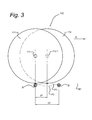
- the reinforcement profiles have a spacing d2, as is indicated in Figure 3 .
- the levelling device is moved in the direction of travel R over the concrete floor A.
- the levelling blade 10 is kept at the height A1 and excess concrete is pushed by the levelling blade in the direction of travel R. Behind the levelling blade, a smooth level surface of the concrete floor then results.
- a concrete floor is subsequently generally finished with the aid of so-called "butterfly machines" before the concrete has fully hardened.
- the wheels 210 of the towing carriage 200 will travel not so much over as through the concrete floor.
- the wheels will rest on the reinforcement profiles B, the top sides of which define a reinforcement plane B1.
- the wheels will thus undergo an upward and downward movement on and below this reinforcement plane B1 owing to the spacing of the reinforcement profiles.
- the blade carriage is provided with two wheel sets, having two wheels each.
- the two wheels in each wheel set each have their own rotation axis transversely to the direction of travel and parallel to the surface to be levelled. This is shown schematically in greater detail in Figure 3 for the right-hand wheel set 110, but applies comparably also to the left-hand wheel set 120.
- the axes 111.1 and 112.1 of respectively the wheels 111 and 112 in the wheel set 110 are displaced over a distance d1 in a direction transversely to the rotation axes and parallel to the direction of travel and a longitudinal axis of the concrete levelling device 1.
- Figure 3 shows that the rotation axis 111.1 of the wheel 111 is located directly above a reinforcement profile B.
- the distance to the following reinforcement profile amounts to a distance d2.
- the bottoms of the wheels now touch a virtual plane B1 extending also over the top sides of the reinforcement profiles B.
- the underside of the wheel 111 follows the curve P1 in Figure 3 . Should a wheel 112 be absent, then the wheel 111, and hence the blade frame, would follow the much deeper curve P2. The frame 150 would then thus undergo a much greater up and down movement than in the described embodiment having two wheels per wheel set.
- the curve P1 will follow a still shallower and smoother course as a result of the influence of the somewhat viscous effect of the fluid concrete floor.
- the design of the blade carriage 100 is such that, when the profile P1 is followed by the bottoms of the wheels, these wheels still touch a virtual flat plane extending (practically) parallel with the plane B1.
- the distance d1 between the wheels is chosen in accordance with the distance d2 between the reinforcement profiles, namely as half the distance d2.
- the distance d1 is hence a fraction of the distance d2, wherein this fraction is given by one divided by the number of wheels, in this illustrative embodiment two wheels.
- a wheel set can be provided with three (or even more) wheels, the axes of which have a spacing d1 equal to (approximately) one-third of the distance d2.
- the height variation of the wheels, and hence of the frame 150, can thus be limited still further.
- the distance d1 between the wheel rotation axes in a wheel set is adjustable in accordance with the distance d2 between the reinforcement profiles B and with the number of wheels in a wheel set, as has been explained above.
- the distance d1 between the wheel rotation axes is the abovementioned fraction plus a whole number of times the distance d2 between the reinforcement profiles, as long as the distance between the rotation axes of wheels in a wheel set is not too large. The blade carriage could then proceed to deform or tilt as it advances over the reinforcement profiles, which is not beneficial to the accuracy of the height adjustment of the levelling blade.
- the wheels 111, 112, 121, 122 in the wheel sets 110, 120 are of narrow construction.
- the width of these wheels is 1 cm.
- the width preferably lies within the range from 0.5 to 3 centimetres.
- the furrows or tracks ploughed by the wheels in the still fluid or viscous concrete will hence be narrow and will easily close up.
- the wheels are made of aluminium, in particular of a cut aluminium plate. Wheels made of other metals or of a plastic are also possible, however.
- the wheels are suspended in a wheel suspension, which is rigidly connected to the blade carriage frame 150.
- the diameter of the wheels is preferably chosen as large as possible, so that the up and down movement of the wheels, and hence of the blade carriage, is limited still further.
- a larger wheel diameter gives a profile P1, as shown in Figure 3 , having a smaller amplitude height.
- a wheel diameter of 60 cm is chosen.
- the blade carriage 100 has a blade carriage frame 150, which is composed of a framework of aluminium profiles or tubes in order to keep this frame, and thus the blade carriage, as light possible. Such frames are also known as truss aluminium or a truss system.
- the hydraulic cylinders 170 are fitted vertically on the rear side on the left-hand and right-hand side of the frame 150.
- the blade frame 160 is coupled with piston rods of the cylinder.
- the piston rods are respectively connected on the bottom and top side of a piston.
- the piston is fitted in a hydraulic cylinder and divides this cylinder 170 into two chambers. Pressures in these two chambers can be regulated separately via the hydraulic lines 175 to enable the blade frame 160 to be moved accurately up and down.
- the levelling blade 10 is fastened on the bottom side to the blade frame 160. To the top side of the blade frame 160 are fastened, on either side, measuring sensors 180 for determining the height of the blade frame and hence of the levelling blade 10, as described above.
- the signal lines 185 and hydraulic lines 175 run to the towing carriage 200, which is coupled by means of the coupling 300 to the front side of the blade carriage 100.
- the hydraulic control unit 270 and the regulator 280 are fitted on the towing carriage.
- the weight hereof is hence present on the towing carriage and not on the blade carriage, which is thus again kept as light as possible.
- an actuator or motor for driving the wheels 210 of the towing carriage for example a hydraulic actuator, and also a power supply in the form of, for example, an electric battery, for providing the various components with an electrical supply.
- the towing carriage has at least one wheel on each side, and possibly more than one wheel in order to distribute the weight.
- These wheels 210 of the towing carriage are provided with wide pneumatic tyres or vulcanized tyres in order to bear the weight. Vulcanized tyres are generally preferred, because these cannot puncture.
- the regulator 280 determines a height difference from the defined height and the measured height. This difference is fed into a PID regulator in the regulator 280, which subsequently drives the hydraulic control unit to provide the cylinder chambers of the cylinders with a pressure.
- the coupling 300 and the described form of the concrete levelling device 1 makes this levelling device very manoeuvrable.
- the wheels of the blade carriage 100 lie practically on a single (virtual) axis line.
- the coupling 300 is shaped such that it prevents articulation of the levelling device about a horizontal axis transversely to a longitudinal axis of towing carriage and blade carriage, and enables pivoting about a vertical axis and torsion about the longitudinal axis.
- this coupling comprises two drawbars 310, 320, situated perpendicularly one above the other, which run horizontally and are each connected to both the blade carriage and the towing carriage, as shown by Figure 1 .
- a first drawbar 310 is rigidly connected by a first end 311 to the towing carriage or the blade carriage, and by the second end 312, by means of a ball joint, to the other of the blade carriage and towing carriage.
- the second drawbar 320 is connected at both ends 321, 322 by means of a ball joint to the blade carriage and the towing carriage.
- a further hydraulic control cylinder (not shown) is also fitted between towing carriage and blade carriage, wherein this control cylinder is fitted horizontally displaced with respect to the two drawbars. At both ends, the control cylinder is connected by means of a ball joint to the blade carriage and towing carriage.
- the assembly comprising blade carriage and towing carriage is steered by means of actuation of the control cylinder.
- the blade carriage 100 and the towing carriage 200 are rigidly connected, wherein these together form a combined blade carriage and towing carriage.
- the front wheels can be realized pivotably to allow the levelling device to be steered.
Landscapes
- Engineering & Computer Science (AREA)
- Architecture (AREA)
- Civil Engineering (AREA)
- Structural Engineering (AREA)
- Mechanical Engineering (AREA)
- On-Site Construction Work That Accompanies The Preparation And Application Of Concrete (AREA)
Applications Claiming Priority (1)
| Application Number | Priority Date | Filing Date | Title |
|---|---|---|---|
| NL2011045A NL2011045C2 (nl) | 2013-06-27 | 2013-06-27 | Systeem van betonvloer en betonvloeregaliseerinrichting, overeenkomstige betonvloeregaliseerinrichting, overeenkomstige werkwijze en betonvloer. |
Publications (2)
| Publication Number | Publication Date |
|---|---|
| EP2853638A2 true EP2853638A2 (fr) | 2015-04-01 |
| EP2853638A3 EP2853638A3 (fr) | 2015-09-30 |
Family
ID=49083728
Family Applications (1)
| Application Number | Title | Priority Date | Filing Date |
|---|---|---|---|
| EP14173570.4A Withdrawn EP2853638A3 (fr) | 2013-06-27 | 2014-06-24 | Système de plancher en béton et de dispositif de mise à niveau de plancher en béton, dispositif de mise à niveau de plancher en béton correspondant, procédé correspondant et plancher en béton |
Country Status (2)
| Country | Link |
|---|---|
| EP (1) | EP2853638A3 (fr) |
| NL (1) | NL2011045C2 (fr) |
Cited By (2)
| Publication number | Priority date | Publication date | Assignee | Title |
|---|---|---|---|---|
| NL2016729B1 (nl) * | 2016-05-03 | 2017-11-10 | Van Berlo Bedrijfsvloeren B V | Betonegaliseerwagen, en Systeem van Betonvloer en een dergelijke Egaliseerwagen |
| CN111794479A (zh) * | 2020-07-24 | 2020-10-20 | 青岛磊莎工业自动化设备有限公司 | 一种自动铺设环氧地坪的装置 |
Families Citing this family (1)
| Publication number | Priority date | Publication date | Assignee | Title |
|---|---|---|---|---|
| CN108729635B (zh) * | 2018-07-12 | 2023-10-24 | 南通承悦装饰集团有限公司 | 一种机电式地板龙骨自动检测调平装置及其使用方法 |
Family Cites Families (3)
| Publication number | Priority date | Publication date | Assignee | Title |
|---|---|---|---|---|
| WO1999019568A1 (fr) * | 1997-10-15 | 1999-04-22 | Munoz Armando G | Appareil et procede de preparation d'un chantier et de finition de beton coule |
| EP1325993A1 (fr) * | 2002-01-07 | 2003-07-09 | Thomas Cincis | Appareil et méthode de lissage |
| WO2006014909A2 (fr) * | 2004-07-26 | 2006-02-09 | Somero Enterprises, Inc. | Dispositif a araser motorise |
-
2013
- 2013-06-27 NL NL2011045A patent/NL2011045C2/nl not_active IP Right Cessation
-
2014
- 2014-06-24 EP EP14173570.4A patent/EP2853638A3/fr not_active Withdrawn
Non-Patent Citations (1)
| Title |
|---|
| None |
Cited By (2)
| Publication number | Priority date | Publication date | Assignee | Title |
|---|---|---|---|---|
| NL2016729B1 (nl) * | 2016-05-03 | 2017-11-10 | Van Berlo Bedrijfsvloeren B V | Betonegaliseerwagen, en Systeem van Betonvloer en een dergelijke Egaliseerwagen |
| CN111794479A (zh) * | 2020-07-24 | 2020-10-20 | 青岛磊莎工业自动化设备有限公司 | 一种自动铺设环氧地坪的装置 |
Also Published As
| Publication number | Publication date |
|---|---|
| EP2853638A3 (fr) | 2015-09-30 |
| NL2011045C2 (nl) | 2015-01-05 |
Similar Documents
| Publication | Publication Date | Title |
|---|---|---|
| US12179535B2 (en) | Automotive construction machine, as well as lifting column for a construction machine | |
| US10435066B2 (en) | Road paver with steering compensation and control method | |
| CN101748680B (zh) | 用于铺设铺路垫块的方法 | |
| CN114585784B (zh) | 用于筑路机的调平系统 | |
| US10246130B2 (en) | Trackless tugger train and method for steering a trackless tugger train | |
| US9663904B2 (en) | Texture curing machine as well as method for the subsequent treatment of a freshly produced concrete layer | |
| EP2853638A2 (fr) | Système de plancher en béton et de dispositif de mise à niveau de plancher en béton, dispositif de mise à niveau de plancher en béton correspondant, procédé correspondant et plancher en béton | |
| DE3909583A1 (de) | Strassenfertiger | |
| HU189887B (en) | Movable line-packing,levelling and correcting machine | |
| US4231678A (en) | Paving machines | |
| CN210104501U (zh) | 滑模摊铺机 | |
| JPH10245809A (ja) | 道路仕上げ機 | |
| CN115075096A (zh) | 具有调平级联控制的道路整修机 | |
| CN215361328U (zh) | 一种基于自动调节的隧道施工用台车行走机构 | |
| NL2016729B1 (nl) | Betonegaliseerwagen, en Systeem van Betonvloer en een dergelijke Egaliseerwagen | |
| TWI573003B (zh) | 可執行自動著地與自動調平作業之頂平系統 | |
| JPH073042B2 (ja) | 敷均し機械におけるスクリードの初期設定方法 | |
| CN121382249A (zh) | 一种长大明挖衬砌模板台车多自由度姿态控制系统及方法 | |
| GB1600501A (en) | Road surfacing machine | |
| ITRM20120674A1 (it) | Frangizolle polivalente a controllo elettronico |
Legal Events
| Date | Code | Title | Description |
|---|---|---|---|
| PUAI | Public reference made under article 153(3) epc to a published international application that has entered the european phase |
Free format text: ORIGINAL CODE: 0009012 |
|
| 17P | Request for examination filed |
Effective date: 20140624 |
|
| AK | Designated contracting states |
Kind code of ref document: A2 Designated state(s): AL AT BE BG CH CY CZ DE DK EE ES FI FR GB GR HR HU IE IS IT LI LT LU LV MC MK MT NL NO PL PT RO RS SE SI SK SM TR |
|
| AX | Request for extension of the european patent |
Extension state: BA ME |
|
| PUAL | Search report despatched |
Free format text: ORIGINAL CODE: 0009013 |
|
| AK | Designated contracting states |
Kind code of ref document: A3 Designated state(s): AL AT BE BG CH CY CZ DE DK EE ES FI FR GB GR HR HU IE IS IT LI LT LU LV MC MK MT NL NO PL PT RO RS SE SI SK SM TR |
|
| AX | Request for extension of the european patent |
Extension state: BA ME |
|
| RIC1 | Information provided on ipc code assigned before grant |
Ipc: E04G 21/10 20060101ALI20150827BHEP Ipc: E01C 19/40 20060101ALI20150827BHEP Ipc: E04F 21/24 20060101ALI20150827BHEP Ipc: E01C 19/42 20060101AFI20150827BHEP |
|
| R17P | Request for examination filed (corrected) |
Effective date: 20160325 |
|
| RBV | Designated contracting states (corrected) |
Designated state(s): AL AT BE BG CH CY CZ DE DK EE ES FI FR GB GR HR HU IE IS IT LI LT LU LV MC MK MT NL NO PL PT RO RS SE SI SK SM TR |
|
| GRAP | Despatch of communication of intention to grant a patent |
Free format text: ORIGINAL CODE: EPIDOSNIGR1 |
|
| INTG | Intention to grant announced |
Effective date: 20170516 |
|
| STAA | Information on the status of an ep patent application or granted ep patent |
Free format text: STATUS: THE APPLICATION IS DEEMED TO BE WITHDRAWN |
|
| 18D | Application deemed to be withdrawn |
Effective date: 20170927 |