EP2853712A1 - Réservoir de surtension anti-dispersion pour eau de refroidissement - Google Patents
Réservoir de surtension anti-dispersion pour eau de refroidissement Download PDFInfo
- Publication number
- EP2853712A1 EP2853712A1 EP20130195797 EP13195797A EP2853712A1 EP 2853712 A1 EP2853712 A1 EP 2853712A1 EP 20130195797 EP20130195797 EP 20130195797 EP 13195797 A EP13195797 A EP 13195797A EP 2853712 A1 EP2853712 A1 EP 2853712A1
- Authority
- EP
- European Patent Office
- Prior art keywords
- cooling water
- surge tank
- pressure cap
- deformation
- cap
- Prior art date
- Legal status (The legal status is an assumption and is not a legal conclusion. Google has not performed a legal analysis and makes no representation as to the accuracy of the status listed.)
- Granted
Links
Images


Classifications
-
- F—MECHANICAL ENGINEERING; LIGHTING; HEATING; WEAPONS; BLASTING
- F01—MACHINES OR ENGINES IN GENERAL; ENGINE PLANTS IN GENERAL; STEAM ENGINES
- F01P—COOLING OF MACHINES OR ENGINES IN GENERAL; COOLING OF INTERNAL-COMBUSTION ENGINES
- F01P11/00—Component parts, details, or accessories not provided for in, or of interest apart from, groups F01P1/00 - F01P9/00
- F01P11/02—Liquid-coolant filling, overflow, venting, or draining devices
- F01P11/029—Expansion reservoirs
-
- F—MECHANICAL ENGINEERING; LIGHTING; HEATING; WEAPONS; BLASTING
- F01—MACHINES OR ENGINES IN GENERAL; ENGINE PLANTS IN GENERAL; STEAM ENGINES
- F01P—COOLING OF MACHINES OR ENGINES IN GENERAL; COOLING OF INTERNAL-COMBUSTION ENGINES
- F01P11/00—Component parts, details, or accessories not provided for in, or of interest apart from, groups F01P1/00 - F01P9/00
- F01P11/02—Liquid-coolant filling, overflow, venting, or draining devices
- F01P11/0204—Filling
- F01P11/0209—Closure caps
- F01P11/0214—Mounting
-
- F—MECHANICAL ENGINEERING; LIGHTING; HEATING; WEAPONS; BLASTING
- F01—MACHINES OR ENGINES IN GENERAL; ENGINE PLANTS IN GENERAL; STEAM ENGINES
- F01P—COOLING OF MACHINES OR ENGINES IN GENERAL; COOLING OF INTERNAL-COMBUSTION ENGINES
- F01P11/00—Component parts, details, or accessories not provided for in, or of interest apart from, groups F01P1/00 - F01P9/00
- F01P11/02—Liquid-coolant filling, overflow, venting, or draining devices
- F01P11/0204—Filling
- F01P11/0209—Closure caps
- F01P11/0238—Closure caps with overpressure valves or vent valves
-
- F—MECHANICAL ENGINEERING; LIGHTING; HEATING; WEAPONS; BLASTING
- F01—MACHINES OR ENGINES IN GENERAL; ENGINE PLANTS IN GENERAL; STEAM ENGINES
- F01P—COOLING OF MACHINES OR ENGINES IN GENERAL; COOLING OF INTERNAL-COMBUSTION ENGINES
- F01P11/00—Component parts, details, or accessories not provided for in, or of interest apart from, groups F01P1/00 - F01P9/00
- F01P11/02—Liquid-coolant filling, overflow, venting, or draining devices
- F01P11/0204—Filling
- F01P11/0209—Closure caps
- F01P11/0214—Mounting
- F01P2011/0228—Sealing
-
- Y—GENERAL TAGGING OF NEW TECHNOLOGICAL DEVELOPMENTS; GENERAL TAGGING OF CROSS-SECTIONAL TECHNOLOGIES SPANNING OVER SEVERAL SECTIONS OF THE IPC; TECHNICAL SUBJECTS COVERED BY FORMER USPC CROSS-REFERENCE ART COLLECTIONS [XRACs] AND DIGESTS
- Y10—TECHNICAL SUBJECTS COVERED BY FORMER USPC
- Y10T—TECHNICAL SUBJECTS COVERED BY FORMER US CLASSIFICATION
- Y10T137/00—Fluid handling
- Y10T137/8593—Systems
- Y10T137/86292—System with plural openings, one a gas vent or access opening
Definitions
- Exemplary embodiments of the present invention relate to a surge tank, and particularly, to a cooling water scatter preventing surge tank capable of basically blocking overflowing vapor and cooling water from leaking or scattering even when the surge tank is tilted.
- a cooling water storing function an air discharge operation within an engine and a radiator, and a supply of cooling water at the time of generating a vacuum pressure within the engine are performed in a surge tank.
- the surge tank is provided with a cooling water supply port acting as a path through which the cooling water is supplied to the engine side at the time of exchanging the cooling water and an overflow discharge port serving as a path through which vapor and the cooling water discharged from an inside of the surge tank when a pressure rises to 0.7 bar or more are discharged to the outside and is fastened with a pressure cap so as to hold the inside of the surge tank at a constant pressure of 0.7 bar.
- the pressure cap is a part which forms a pressure in a cooling system at approximately 0.7 bar so as to increase a boiling point of the cooling water and is opened when the pressure rises to 0.7 bar or more and has a structure satisfying a vapor discharge condition without discharging the cooling water within the surge tank.
- the surge tank is installed in a vehicle which encounters various driving conditions and thus may be in a situation out of design requirements of the pressure cap. In this situation, the requirements of the pressure cap which discharges only the vapor without discharging the cooling water within the surge tank may not be satisfied.
- the surge tank is also tilted as much as a tilt of a vehicle which drives a sloping road having a high and long gradient condition and thus a level of the cooling water within the surge tank moves as much as the tilt, such that the cooling water pulls toward the pressure cap, thereby discharging the cooling water.
- the pressure cap when the pressure cap is opened by the internal pressure rising to 0.7 bar or more in the tilted state of the surge tank, the vapor and the cooling water are not normally discharged through the overflow discharge port but is discharged through the fastened portion of the pressure cap, such that a peripheral portion of the surge tank may be polluted.
- Various aspects of the present invention are directed to providing a cooling water scatter preventing type surge tank capable of preventing a peripheral portion of a surge tank from being polluted by blocking overflowing vapor and cooling water from leaking or scattering to the peripheral portion of the surge tank when a pressure cap is opened by an internal pressure rising to 0.7 bar or more, in particular, basically blocking the cooling water from being discharged through a fastened portion of the pressure cap even though the pressure cap is opened in a cooling water pulling state due to the tilt of the surge tank, thereby preventing the peripheral portion of the surge tank from being polluted.
- a cooling water scatter preventing type surge tank assembly may include a pressure cap, a cap coupling boss, a multi-deformation ring mounted to the pressure cap and selectively engaged to the cap coupling boss to form a receiving space between the pressure cap and the cap coupling boss, wherein the multi-deformation ring is configured to collect vapor or cooling water discharged through a discharge path opened when a pressure of the vapor or the cooling water rises to an allowable pressure or more, to the receiving space connected to an overflow port, to block the receiving space from the outside by the pressure cap, and to be deformed by the pressure cap to perform sealing processing on the receiving space double.
- the multi-deformation ring is deformed by a fastening force of the pressure cap with the receiving space in a state in which an end of the multi-deformation ring is inserted into the pressure cap to perform the sealing processing on the receiving space double.
- the end of the multi-deformation ring is fitted in a ring groove which is formed in the pressure cap.
- the pressure cap is provided with a concentric flange in which the ring groove is formed to be assembled with the multi-deformation ring, wherein the concentric flange is disposed concentrically on a pressure cap body of the pressure cap which is fastened with a filler neck protruding from the cap coupling boss in the receiving space communicating with an inside of a surge tank, and wherein the pressure cap body is provided with a gasket which selectively contacts a top surface of the filler neck.
- the multi-deformation ring is made of a plate rubber material.
- the multi-deformation ring may include a circular body having an annular ring shape and configured to be coupled to the pressure cap, and a deformation protrusion and a deformation wing which are integrally formed at an outer edge of the circular body, and wherein the deformation wing and the deformation protrusion each seal the receiving space by contacting an outer wall of the cap coupling boss to perform the sealing processing on the receiving space double, wherein the receiving space is enclosed by the outer wall of the cap coupling boss and the pressure cap.
- the deformation wing protrudes outside of an outer edge of the circular body in a horizontal section of the circular body and the deformation protrusion protrudes downward from the deformation wing.
- the deformation protrusion and the deformation ring each may have a triangular shape.
- the receiving space communicating with the inside of a surge tank is formed between a filler neck and an outer wall, the filler neck being formed to protrude from the cap coupling boss and configured to be fastened with the pressure cap along with a gasket, and the outer wall protruding from the cap coupling boss to enclose the filler neck in a concentric circle to form the receiving space therebetween.
- the outer wall, the filler neck, and the receiving space are formed as a space in which the cooling water is expanded, in the surge tank.
- An inner peripheral surface of the pressure cap is provided with a female screw and an outer peripheral surface of the filler neck is provided with a male screw such that the pressure cap is configured to be selectively engaged with the filler neck.
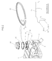
- FIG. 1 illustrates a configuration of a cooling water scatter preventing type surge tank in accordance with an exemplary embodiment of the present invention.
- a surge tank 1 is formed to have a shape having an inner space filled with cooling water, in which a bottom surface portion thereof is integrally provided with an overflow port 3 along with a cooling water supply port 2, and a top surface portion thereof is integrally provided with a cap coupling boss 10 with which the pressure cap 30 is screw fastened.
- a lower space forming a bottom portion is divided into a cooling water space A filled with cooling water, while an upper space forming a top portion is divided into a cooling water expansion space B which is a spare space in which the cooling water may be expanded at the time of a temperature rise of an engine (at the time of hot starting).
- the cooling water supply port 2 is disposed at the bottom portion of the surge tank 1, while the cap fastening boss 10 is disposed at the top portion of the surge tank 1, and the overflow port 3 communicates with the cap fastening boss 10 while being disposed at the bottom portion of the surge tank 1, such that vapor or overflowing cooling water may be discharged outside of the surge tank 1 when the pressure cap 30 is opened.
- the cap fastening boss 10 is configured to include an outer wall 11 which protrudes from the top surface of the surge tank 1 to form an opened inner space, a filler neck 13 which protrudes in a hollow pipe form so as to communicate with an inside of the surge tank 1 in the inner space of the outer wall 11, and a receiving space 15 in which the filler neck 13 having a concentric circle shape is formed at the outer wall 11.
- the outer wall 11 protrudes a relatively lower height than the filler neck 13 and an outer peripheral surface of the filler neck 13 is provided with a male screw to be screw fastened with a female screw of the pressure cap 30.
- the receiving space 15 forms a path through which when the pressure cap 30 is opened, the vapor or the overflowing cooling water may be discharged outside of the surge tank 1 and has at least one stepped section structure to more relieve the flow of cooling water.
- the pressure cap 30 is provided with the female screw which is inserted into an inlet of the filler neck 13 and is screw fastened with the male screw of the filler neck 13 and the inside of the pressure cap 30 is provided with a groove into which a gasket 40 is inserted.
- the pressure cap 30 is provided with a multi-deformation ring 50 along with the gasket 40 to increase sealability of the inside of the surge tank 1, and in particular, when the pressure cap 30 is opened, a phenomenon that the vapor or the overflowing cooling water scatters through the cap fastening boss 10 in the surge tank 1 is prevented.
- the gasket 40 adheres to the top surface of the filler neck 13 in the state in which the pressure cap 30 is fastened with the filler neck 13 to provide the sealability, thereby forming a pressure of 0.7 bar.
- the multi-deformation ring 50 adheres to an inner surface of the outer wall 11 in the state in which the pressure cap 30 is fastened with the filler neck 13 to prevent the vapor or the overflowing cooling water from scattering through the cap fastening boss 10 in the surge tank 1 when the pressure cap 30 is opened.
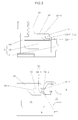
- FIG. 2 illustrates a detailed configuration of the multi-deformation ring 50 which is separated from the pressure cap 30.
- the multi-deformation ring 50 is configured to include a circular body 51 having an annular ring shape and a circular protruding body 53 which is integrally formed at an outer edge of the circular body 51 to expand a diameter of the circular body 51.
- the circular body 51 is inserted into the pressure cap 30 to serve to assemble the multi-deformation ring 50 with the pressure cap 30.
- the circular protruding body 53 is configured to include a deformation wing 53-2 which protrudes outside of an edge of the circular body 51 from a horizontal section of the circular body 51 to expand the diameter of the circular body 51 and a deformation protrusion 53-1 which protrudes downwardly from the deformation wing 53-2 to expand a width thickness of the circular body 51.
- the deformation protrusion 53-1 performs a primary sealing operation so as to be adhere between the pressure cap 30 and the outer wall 11 of the cap fastening boss 10, in particular, an operation of more improving an adhesion by receiving a pressure generated from the inside of the pressure cap 30 so as to be pushed to the outside.
- the deformation wing 53-2 performs a secondary sealing operation to adhere between the pressure cap 30 and the outer wall 11 of the cap fastening boss 10 above the deformation protrusion 53-1.
- the deformation protrusion 53-1 and the deformation wing 53-2 have a triangular shape and have a high deformation degree at the time of adhering to a contact portion, thereby more strengthening the adhesion.
- the shape of the deformation protrusion 53-1 and the deformation wing 53-2 is not limited to the triangular shape.
- the deformation wing 53-2 and the deformation protrusion 53-1 are made of a plate rubber material and formed to have a relatively thinner thickness, thereby maximizing a sealing operation while minimizing a friction force at the time of tightening the pressure cap 30.
- the minimization of the friction force means the state in which the sealing action of the gasket 40 against the filler neck 13 at the time of tightening the pressure cap 30 is not reduced.
- the overall multi-deformation ring 50 may be made of the plate rubber material.
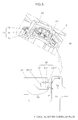
- FIG. 3 illustrates the assembled state of the pressure cap and the multi-deformation ring.
- the pressure cap 30 is provided with a concentric flange 31 which is disposed between the outer wall 11 and the filler neck 13 and the concentric flange 31 is further provided with a ring groove 31-1 which is depressed along an edge of the concentric flange 31, such that the multi-deformation ring 50 may be inserted into the concentric flange 31.
- the multi-deformation ring 50 is in contact with an inner peripheral surface of the outer wall 11 while the pressure cap 30 goes down along the filler neck 13, and the fastening of the pressure cap 30 is further progressed, such that the primary sealing by the deformation protrusion 53-1 and the secondary sealing by the deformation wing 53-2 may be formed.
- the deformation protrusion 53-1 suffers from a position deformation a-1 to be lifted up from an initial position a, such that an adhering state Sa to the inner peripheral surface of the outer wall 11 may be more strengthened.
- the deformation wing 53-2 suffers from a position deformation b-1 to be lifted up from an initial position b, such that an adhering state Sb to the inner peripheral surface of the outer wall 11 may be more strengthened.
- FIG. 4 illustrates an operation state of the pressure cap depending on a change in posture of the surge tank in accordance with the exemplary embodiment of the present invention.
- the surge tank 1 is tilted due to a vehicle which drives a sloping road having a high and long gradient condition and cooling water 100 filled in the surge tank 1 is in a pulled state toward the pressure cap 30 due to the sloping road and in this state, the pressure cap 30 is in an opened state due to a pressure of 0.7 bar or more.
- the pressure cap 30 is further provided with the multi-deformation ring 50 which forms a double sealing, such that the vapor or the overflowing cooling water discharged from the inside of the surge tank 1 due to the opening of the pressure cap 30 may be collected to the receiving space 15 and then the flow of vapor or overflowing cooling water discharged through the overflow port 3 connected to the receiving space 15 may be smoothly performed.
- the vapor or the overflowing cooling water discharged from the inside of the surge tank 1 due to the opening of the pressure cap 30 is collected to the receiving space 15, but the deformation protrusion 53-1 performing the primary sealing operation of the multi-deformation ring 50 prevents the cooling water from splashing.
- the cooling water blocked by the deformation protrusion 53-1 may not move toward the deformation wing 53-2 and even though the cooling water moving toward the deformation wing 53-2 is present, the cooling water is again blocked by the deformation wing 53-2 and thus does not deviate from the cap fastening boss 10.
- the sealing operation is more strengthened by the adhering state Sa due to the deformation of the deformation protrusion 53-1 and the adhering state Sb due to the deformation of the deformation wing 53-2, such that the movement of the cooling water may be completely blocked.
- the cooling water scatter preventing type surge tank in accordance with the exemplary embodiment of the present invention further includes the multi-deformation ring 50 which collects the vapor or the cooling water, which is discharged through the discharge path opened when the pressure rises to an allowable pressure or more, to the receiving space 15 connected to the overflow port 3, blocks the receiving space 15 from the outside by the pressure cap 30, and is deformed by the pressure cap 30 to perform the sealing processing on the receiving space 15 double, such that the leaking or scattering of the overflowing vapor and cooling water to the peripheral portion of the surge tank may be blocked when the pressure cap is opened by the internal pressure rising to 0.7 bar or more.
- the multi-deformation ring 50 basically blocks the cooling water from being discharged through the fastened portion of the pressure cap, thereby preventing the peripheral portion of the surge tank from being polluted.
- the pressure cap holding 0.7 bar and opened at the time of 0.7 bar or more and satisfying the condition of preventing the cooling water from scattering to the outside at the time of pulling the cooling water while satisfying the vapor discharge condition without discharging the cooling water may be applied to the surge tank, thereby remarkably improving the performance of the surge tank.
- the pressure cap even though the pressure cap is opened in the cooling water pulling state due to the tilt of the surge tank, the pressure cap may basically block the cooling water from scattering to the outside, thereby preventing the peripheral portion of the surge tank from being polluted.
- the scattering of the cooling water to the outside is basically blocked in the cooling water pulling state due to the tilt of the surge tank by applying the multi-deformation ring inserted into the pressure cap, such that there is little increase in additional cost due to the change in design of the pressure cap and the surge tank and the productivity is remarkably improved due to the improvement in the performance of the surge tank.
Landscapes
- Engineering & Computer Science (AREA)
- Chemical & Material Sciences (AREA)
- Combustion & Propulsion (AREA)
- Mechanical Engineering (AREA)
- General Engineering & Computer Science (AREA)
- Pressure Vessels And Lids Thereof (AREA)
- Closures For Containers (AREA)
Applications Claiming Priority (1)
| Application Number | Priority Date | Filing Date | Title |
|---|---|---|---|
| KR20130114448A KR101459949B1 (ko) | 2013-09-26 | 2013-09-26 | 냉각수 비산 방지 타입 서지탱크 |
Publications (2)
| Publication Number | Publication Date |
|---|---|
| EP2853712A1 true EP2853712A1 (fr) | 2015-04-01 |
| EP2853712B1 EP2853712B1 (fr) | 2018-08-15 |
Family
ID=49919979
Family Applications (1)
| Application Number | Title | Priority Date | Filing Date |
|---|---|---|---|
| EP13195797.9A Not-in-force EP2853712B1 (fr) | 2013-09-26 | 2013-12-05 | Réservoir de surtension anti-dispersion pour eau de refroidissement |
Country Status (4)
| Country | Link |
|---|---|
| US (1) | US20150083252A1 (fr) |
| EP (1) | EP2853712B1 (fr) |
| KR (1) | KR101459949B1 (fr) |
| CN (1) | CN104512612B (fr) |
Families Citing this family (3)
| Publication number | Priority date | Publication date | Assignee | Title |
|---|---|---|---|---|
| CN105822405A (zh) * | 2016-05-26 | 2016-08-03 | 潍柴动力股份有限公司 | 一种膨胀水箱 |
| US10487718B2 (en) * | 2016-11-22 | 2019-11-26 | Ford Global Technologies, Llc | Overflow cap air vent |
| CN120739609B (zh) * | 2025-08-21 | 2025-11-11 | 恒勃控股股份有限公司 | 膨胀水箱以及新能源车用热管理系统 |
Citations (4)
| Publication number | Priority date | Publication date | Assignee | Title |
|---|---|---|---|---|
| JPS5588015U (fr) * | 1978-12-12 | 1980-06-18 | ||
| JPS56129520U (fr) * | 1980-03-04 | 1981-10-01 | ||
| US20020035874A1 (en) * | 2000-09-28 | 2002-03-28 | Toyo Radiator Co., Ltd. | Pressure cap |
| EP1268993B1 (fr) * | 2000-03-31 | 2006-01-25 | REUTTER, Heinrich | Bouchon de fermeture |
Family Cites Families (30)
| Publication number | Priority date | Publication date | Assignee | Title |
|---|---|---|---|---|
| US2732971A (en) * | 1956-01-31 | Radiator caps | ||
| US2171168A (en) * | 1934-07-16 | 1939-08-29 | Eaton Mfg Co | Radiator cap assembly |
| US2535974A (en) * | 1947-07-02 | 1950-12-26 | Robertshaw Fulton Controls Co | Thermostatically controlled pressure cap for radiators |
| US3053408A (en) * | 1960-09-08 | 1962-09-11 | Stant Mfg Company Inc | Radiator cap with safety gasket |
| US3164288A (en) * | 1963-01-10 | 1965-01-05 | C J Boomgaard | Closure and valve construction |
| US3216608A (en) * | 1963-09-12 | 1965-11-09 | Dole Valve Co | Pressure cap for sealed cooling system |
| US3434621A (en) * | 1966-08-23 | 1969-03-25 | Eaton Yale & Towne | Safety pressure cap |
| US3601181A (en) * | 1970-03-09 | 1971-08-24 | Saf Gard Products Inc | Method and apparatus for purging air from internal combustion engine cooling systems |
| US3715049A (en) * | 1971-10-20 | 1973-02-06 | Gen Motors Corp | Radiator pressure cap |
| US4196822A (en) * | 1971-10-29 | 1980-04-08 | Avrea Walter C | Monolithic radiator cap for sealed pressurized cooling system |
| US3910451A (en) * | 1973-10-01 | 1975-10-07 | Arthur P Tusing | Radiator cap |
| US3878965A (en) * | 1974-05-13 | 1975-04-22 | Stant Mfg Co | Pressure-vacuum relief vehicle radiator cap with free-turning shell |
| US4185751A (en) * | 1978-07-31 | 1980-01-29 | Stant Manufacturing Company, Inc. | Radiator cap |
| US4790369A (en) * | 1982-04-29 | 1988-12-13 | Avrea Walter C | Method and apparatus for continuously maintaining a volume of coolant within a pressurized cooling system |
| USRE32434E (en) * | 1982-04-29 | 1987-06-09 | Method and apparatus for automatically refilling a leaking liquid cooling system as an engine operates by utilizing a radiator and a remote coolant reservoir | |
| US4498599A (en) * | 1983-08-15 | 1985-02-12 | Avrea Walter C | Closure and valving apparatus |
| DE8901826U1 (de) * | 1988-11-23 | 1989-04-06 | Reutter Metallwarenfabrik GmbH, 71336 Waiblingen | Kühlerstutzen mit Verschlußdeckel |
| DE4124182C1 (fr) * | 1991-07-20 | 1992-06-04 | Mercedes-Benz Aktiengesellschaft, 7000 Stuttgart, De | |
| US5114035A (en) * | 1991-10-31 | 1992-05-19 | Epicor Industries, Inc. | Vehicle radiator cap |
| US5169015A (en) * | 1992-02-20 | 1992-12-08 | Stant Corporation | Vehicle radiator cap with auxiliary vacuum seal |
| US5248052A (en) * | 1992-07-31 | 1993-09-28 | Mellinger Larry L | Apparatus for automatically releasing the super-atmospheric pressure of an engine cooling system in response to turning off the engine and preventing the buildup of pressure while the engine is off |
| DE4233038C1 (de) * | 1992-10-01 | 1993-11-25 | Daimler Benz Ag | Überdrucksicherung für einen Kühlmittelkreislauf |
| US5522456A (en) * | 1994-06-22 | 1996-06-04 | Geiger Technic, Inc. | Overflow with threaded plastic fillneck for surge tanks and overflow reservoirs |
| US6276312B1 (en) * | 1998-11-06 | 2001-08-21 | Stant Manufacturing Inc. | Thermal control cooling system vacuum valve |
| JP4106820B2 (ja) * | 1999-07-14 | 2008-06-25 | 株式会社デンソー | 完全密閉型容器 |
| AT4061U1 (de) * | 1999-09-08 | 2001-01-25 | Tesma Motoren Getriebetechnik | Verschlussstopfen für einen füllstutzen eines kraftstoffbehälters |
| JP2002228028A (ja) * | 2001-01-31 | 2002-08-14 | Toyo Radiator Co Ltd | ラジエータのプレッシャバルブ付きキャップ |
| US6892587B2 (en) * | 2002-03-08 | 2005-05-17 | Ntn Corporation | Rotation detecting device and wheel support bearing assembly utilizing the same |
| GB2405905B (en) * | 2002-04-23 | 2006-05-24 | Nsk Ltd | Method of assembly for seal apparatus for water pump, rotation support apparatus for water pump, and water pump |
| JP3932513B2 (ja) * | 2002-12-25 | 2007-06-20 | 株式会社ティラド | プレッシャバルブ付きラジエータキャップ |
-
2013
- 2013-09-26 KR KR20130114448A patent/KR101459949B1/ko active Active
- 2013-12-05 US US14/098,494 patent/US20150083252A1/en not_active Abandoned
- 2013-12-05 EP EP13195797.9A patent/EP2853712B1/fr not_active Not-in-force
- 2013-12-24 CN CN201310721962.1A patent/CN104512612B/zh not_active Expired - Fee Related
Patent Citations (4)
| Publication number | Priority date | Publication date | Assignee | Title |
|---|---|---|---|---|
| JPS5588015U (fr) * | 1978-12-12 | 1980-06-18 | ||
| JPS56129520U (fr) * | 1980-03-04 | 1981-10-01 | ||
| EP1268993B1 (fr) * | 2000-03-31 | 2006-01-25 | REUTTER, Heinrich | Bouchon de fermeture |
| US20020035874A1 (en) * | 2000-09-28 | 2002-03-28 | Toyo Radiator Co., Ltd. | Pressure cap |
Also Published As
| Publication number | Publication date |
|---|---|
| US20150083252A1 (en) | 2015-03-26 |
| KR101459949B1 (ko) | 2014-11-07 |
| CN104512612B (zh) | 2017-11-24 |
| CN104512612A (zh) | 2015-04-15 |
| EP2853712B1 (fr) | 2018-08-15 |
Similar Documents
| Publication | Publication Date | Title |
|---|---|---|
| US8371326B2 (en) | Fuel vapor vent valve with dynamic pressure relief | |
| JP2006266265A (ja) | 逆向きに流通させる性能を備えた、低めの輪郭のオーバフィル制限装置 | |
| US7527064B2 (en) | Fuel cutoff valve | |
| US20090236350A1 (en) | Ventilating device for fuel tank | |
| JP6295905B2 (ja) | 燃料遮断弁 | |
| US11059368B2 (en) | Fill limit venting valve with high shut-off height | |
| EP2853712A1 (fr) | Réservoir de surtension anti-dispersion pour eau de refroidissement | |
| US9683479B2 (en) | Safety cap device for controlling pressure in radiator and method for controlling pressure using the same | |
| JP2007009906A (ja) | 燃料タンク用ベントバルブ及び燃料ポンプモジュール | |
| US20190113149A1 (en) | Valve device for fuel tank | |
| EP2619042B1 (fr) | Réservoir comprenant un orifice de ventilation | |
| US8636027B2 (en) | Vent with improved seal | |
| US7185638B2 (en) | Fuel tank for a motor vehicle | |
| WO2017068882A1 (fr) | Vanne de commande d'écoulement d'air pour réservoir de carburant | |
| WO2017068884A1 (fr) | Soupape de régulation de flux d'air pour réservoir de carburant | |
| EP2823980B1 (fr) | Soupape d'évacuation d'un réservoir de carburant | |
| US20110017320A1 (en) | Fuel Cutoff valve | |
| US7926506B2 (en) | Tank flow path structure | |
| US8602061B2 (en) | Flow control valve | |
| JP7737122B2 (ja) | リザーブタンク | |
| WO2017068883A1 (fr) | Soupape de commande de mise à l'air libre de réservoir de carburant | |
| JPS6038507Y2 (ja) | 燃料タンクブリ−ザ− | |
| CN205292278U (zh) | 多功能密封燃油箱阀门 | |
| JP2008138732A (ja) | リリーフバルブ | |
| JP2015020547A (ja) | 燃料遮断装置 |
Legal Events
| Date | Code | Title | Description |
|---|---|---|---|
| PUAI | Public reference made under article 153(3) epc to a published international application that has entered the european phase |
Free format text: ORIGINAL CODE: 0009012 |
|
| 17P | Request for examination filed |
Effective date: 20131205 |
|
| AK | Designated contracting states |
Kind code of ref document: A1 Designated state(s): AL AT BE BG CH CY CZ DE DK EE ES FI FR GB GR HR HU IE IS IT LI LT LU LV MC MK MT NL NO PL PT RO RS SE SI SK SM TR |
|
| AX | Request for extension of the european patent |
Extension state: BA ME |
|
| R17P | Request for examination filed (corrected) |
Effective date: 20150827 |
|
| RBV | Designated contracting states (corrected) |
Designated state(s): AL AT BE BG CH CY CZ DE DK EE ES FI FR GB GR HR HU IE IS IT LI LT LU LV MC MK MT NL NO PL PT RO RS SE SI SK SM TR |
|
| GRAP | Despatch of communication of intention to grant a patent |
Free format text: ORIGINAL CODE: EPIDOSNIGR1 |
|
| INTG | Intention to grant announced |
Effective date: 20180309 |
|
| GRAS | Grant fee paid |
Free format text: ORIGINAL CODE: EPIDOSNIGR3 |
|
| GRAA | (expected) grant |
Free format text: ORIGINAL CODE: 0009210 |
|
| AK | Designated contracting states |
Kind code of ref document: B1 Designated state(s): AL AT BE BG CH CY CZ DE DK EE ES FI FR GB GR HR HU IE IS IT LI LT LU LV MC MK MT NL NO PL PT RO RS SE SI SK SM TR |
|
| REG | Reference to a national code |
Ref country code: CH Ref legal event code: EP Ref country code: GB Ref legal event code: FG4D Ref country code: AT Ref legal event code: REF Ref document number: 1030037 Country of ref document: AT Kind code of ref document: T Effective date: 20180815 |
|
| REG | Reference to a national code |
Ref country code: IE Ref legal event code: FG4D |
|
| REG | Reference to a national code |
Ref country code: DE Ref legal event code: R096 Ref document number: 602013041959 Country of ref document: DE |
|
| REG | Reference to a national code |
Ref country code: NL Ref legal event code: MP Effective date: 20180815 |
|
| REG | Reference to a national code |
Ref country code: LT Ref legal event code: MG4D |
|
| REG | Reference to a national code |
Ref country code: AT Ref legal event code: MK05 Ref document number: 1030037 Country of ref document: AT Kind code of ref document: T Effective date: 20180815 |
|
| PG25 | Lapsed in a contracting state [announced via postgrant information from national office to epo] |
Ref country code: FI Free format text: LAPSE BECAUSE OF FAILURE TO SUBMIT A TRANSLATION OF THE DESCRIPTION OR TO PAY THE FEE WITHIN THE PRESCRIBED TIME-LIMIT Effective date: 20180815 Ref country code: NO Free format text: LAPSE BECAUSE OF FAILURE TO SUBMIT A TRANSLATION OF THE DESCRIPTION OR TO PAY THE FEE WITHIN THE PRESCRIBED TIME-LIMIT Effective date: 20181115 Ref country code: GR Free format text: LAPSE BECAUSE OF FAILURE TO SUBMIT A TRANSLATION OF THE DESCRIPTION OR TO PAY THE FEE WITHIN THE PRESCRIBED TIME-LIMIT Effective date: 20181116 Ref country code: IS Free format text: LAPSE BECAUSE OF FAILURE TO SUBMIT A TRANSLATION OF THE DESCRIPTION OR TO PAY THE FEE WITHIN THE PRESCRIBED TIME-LIMIT Effective date: 20181215 Ref country code: RS Free format text: LAPSE BECAUSE OF FAILURE TO SUBMIT A TRANSLATION OF THE DESCRIPTION OR TO PAY THE FEE WITHIN THE PRESCRIBED TIME-LIMIT Effective date: 20180815 Ref country code: NL Free format text: LAPSE BECAUSE OF FAILURE TO SUBMIT A TRANSLATION OF THE DESCRIPTION OR TO PAY THE FEE WITHIN THE PRESCRIBED TIME-LIMIT Effective date: 20180815 Ref country code: AT Free format text: LAPSE BECAUSE OF FAILURE TO SUBMIT A TRANSLATION OF THE DESCRIPTION OR TO PAY THE FEE WITHIN THE PRESCRIBED TIME-LIMIT Effective date: 20180815 Ref country code: SE Free format text: LAPSE BECAUSE OF FAILURE TO SUBMIT A TRANSLATION OF THE DESCRIPTION OR TO PAY THE FEE WITHIN THE PRESCRIBED TIME-LIMIT Effective date: 20180815 Ref country code: BG Free format text: LAPSE BECAUSE OF FAILURE TO SUBMIT A TRANSLATION OF THE DESCRIPTION OR TO PAY THE FEE WITHIN THE PRESCRIBED TIME-LIMIT Effective date: 20181115 Ref country code: LT Free format text: LAPSE BECAUSE OF FAILURE TO SUBMIT A TRANSLATION OF THE DESCRIPTION OR TO PAY THE FEE WITHIN THE PRESCRIBED TIME-LIMIT Effective date: 20180815 |
|
| PG25 | Lapsed in a contracting state [announced via postgrant information from national office to epo] |
Ref country code: LV Free format text: LAPSE BECAUSE OF FAILURE TO SUBMIT A TRANSLATION OF THE DESCRIPTION OR TO PAY THE FEE WITHIN THE PRESCRIBED TIME-LIMIT Effective date: 20180815 Ref country code: AL Free format text: LAPSE BECAUSE OF FAILURE TO SUBMIT A TRANSLATION OF THE DESCRIPTION OR TO PAY THE FEE WITHIN THE PRESCRIBED TIME-LIMIT Effective date: 20180815 Ref country code: HR Free format text: LAPSE BECAUSE OF FAILURE TO SUBMIT A TRANSLATION OF THE DESCRIPTION OR TO PAY THE FEE WITHIN THE PRESCRIBED TIME-LIMIT Effective date: 20180815 |
|
| PG25 | Lapsed in a contracting state [announced via postgrant information from national office to epo] |
Ref country code: ES Free format text: LAPSE BECAUSE OF FAILURE TO SUBMIT A TRANSLATION OF THE DESCRIPTION OR TO PAY THE FEE WITHIN THE PRESCRIBED TIME-LIMIT Effective date: 20180815 Ref country code: PL Free format text: LAPSE BECAUSE OF FAILURE TO SUBMIT A TRANSLATION OF THE DESCRIPTION OR TO PAY THE FEE WITHIN THE PRESCRIBED TIME-LIMIT Effective date: 20180815 Ref country code: RO Free format text: LAPSE BECAUSE OF FAILURE TO SUBMIT A TRANSLATION OF THE DESCRIPTION OR TO PAY THE FEE WITHIN THE PRESCRIBED TIME-LIMIT Effective date: 20180815 Ref country code: IT Free format text: LAPSE BECAUSE OF FAILURE TO SUBMIT A TRANSLATION OF THE DESCRIPTION OR TO PAY THE FEE WITHIN THE PRESCRIBED TIME-LIMIT Effective date: 20180815 Ref country code: CZ Free format text: LAPSE BECAUSE OF FAILURE TO SUBMIT A TRANSLATION OF THE DESCRIPTION OR TO PAY THE FEE WITHIN THE PRESCRIBED TIME-LIMIT Effective date: 20180815 Ref country code: EE Free format text: LAPSE BECAUSE OF FAILURE TO SUBMIT A TRANSLATION OF THE DESCRIPTION OR TO PAY THE FEE WITHIN THE PRESCRIBED TIME-LIMIT Effective date: 20180815 |
|
| REG | Reference to a national code |
Ref country code: DE Ref legal event code: R097 Ref document number: 602013041959 Country of ref document: DE |
|
| PG25 | Lapsed in a contracting state [announced via postgrant information from national office to epo] |
Ref country code: SM Free format text: LAPSE BECAUSE OF FAILURE TO SUBMIT A TRANSLATION OF THE DESCRIPTION OR TO PAY THE FEE WITHIN THE PRESCRIBED TIME-LIMIT Effective date: 20180815 Ref country code: SK Free format text: LAPSE BECAUSE OF FAILURE TO SUBMIT A TRANSLATION OF THE DESCRIPTION OR TO PAY THE FEE WITHIN THE PRESCRIBED TIME-LIMIT Effective date: 20180815 Ref country code: DK Free format text: LAPSE BECAUSE OF FAILURE TO SUBMIT A TRANSLATION OF THE DESCRIPTION OR TO PAY THE FEE WITHIN THE PRESCRIBED TIME-LIMIT Effective date: 20180815 |
|
| PLBE | No opposition filed within time limit |
Free format text: ORIGINAL CODE: 0009261 |
|
| STAA | Information on the status of an ep patent application or granted ep patent |
Free format text: STATUS: NO OPPOSITION FILED WITHIN TIME LIMIT |
|
| 26N | No opposition filed |
Effective date: 20190516 |
|
| REG | Reference to a national code |
Ref country code: CH Ref legal event code: PL |
|
| PG25 | Lapsed in a contracting state [announced via postgrant information from national office to epo] |
Ref country code: SI Free format text: LAPSE BECAUSE OF FAILURE TO SUBMIT A TRANSLATION OF THE DESCRIPTION OR TO PAY THE FEE WITHIN THE PRESCRIBED TIME-LIMIT Effective date: 20180815 Ref country code: LU Free format text: LAPSE BECAUSE OF NON-PAYMENT OF DUE FEES Effective date: 20181205 Ref country code: MC Free format text: LAPSE BECAUSE OF FAILURE TO SUBMIT A TRANSLATION OF THE DESCRIPTION OR TO PAY THE FEE WITHIN THE PRESCRIBED TIME-LIMIT Effective date: 20180815 |
|
| REG | Reference to a national code |
Ref country code: IE Ref legal event code: MM4A |
|
| REG | Reference to a national code |
Ref country code: BE Ref legal event code: MM Effective date: 20181231 |
|
| PG25 | Lapsed in a contracting state [announced via postgrant information from national office to epo] |
Ref country code: IE Free format text: LAPSE BECAUSE OF NON-PAYMENT OF DUE FEES Effective date: 20181205 |
|
| PG25 | Lapsed in a contracting state [announced via postgrant information from national office to epo] |
Ref country code: BE Free format text: LAPSE BECAUSE OF NON-PAYMENT OF DUE FEES Effective date: 20181231 |
|
| PG25 | Lapsed in a contracting state [announced via postgrant information from national office to epo] |
Ref country code: LI Free format text: LAPSE BECAUSE OF NON-PAYMENT OF DUE FEES Effective date: 20181231 Ref country code: CH Free format text: LAPSE BECAUSE OF NON-PAYMENT OF DUE FEES Effective date: 20181231 |
|
| PG25 | Lapsed in a contracting state [announced via postgrant information from national office to epo] |
Ref country code: MT Free format text: LAPSE BECAUSE OF NON-PAYMENT OF DUE FEES Effective date: 20181205 |
|
| PG25 | Lapsed in a contracting state [announced via postgrant information from national office to epo] |
Ref country code: TR Free format text: LAPSE BECAUSE OF FAILURE TO SUBMIT A TRANSLATION OF THE DESCRIPTION OR TO PAY THE FEE WITHIN THE PRESCRIBED TIME-LIMIT Effective date: 20180815 |
|
| PG25 | Lapsed in a contracting state [announced via postgrant information from national office to epo] |
Ref country code: PT Free format text: LAPSE BECAUSE OF FAILURE TO SUBMIT A TRANSLATION OF THE DESCRIPTION OR TO PAY THE FEE WITHIN THE PRESCRIBED TIME-LIMIT Effective date: 20180815 |
|
| PG25 | Lapsed in a contracting state [announced via postgrant information from national office to epo] |
Ref country code: CY Free format text: LAPSE BECAUSE OF FAILURE TO SUBMIT A TRANSLATION OF THE DESCRIPTION OR TO PAY THE FEE WITHIN THE PRESCRIBED TIME-LIMIT Effective date: 20180815 Ref country code: HU Free format text: LAPSE BECAUSE OF FAILURE TO SUBMIT A TRANSLATION OF THE DESCRIPTION OR TO PAY THE FEE WITHIN THE PRESCRIBED TIME-LIMIT; INVALID AB INITIO Effective date: 20131205 Ref country code: MK Free format text: LAPSE BECAUSE OF NON-PAYMENT OF DUE FEES Effective date: 20180815 |
|
| PGFP | Annual fee paid to national office [announced via postgrant information from national office to epo] |
Ref country code: GB Payment date: 20221121 Year of fee payment: 10 Ref country code: FR Payment date: 20221121 Year of fee payment: 10 Ref country code: DE Payment date: 20220621 Year of fee payment: 10 |
|
| P01 | Opt-out of the competence of the unified patent court (upc) registered |
Effective date: 20230530 |
|
| REG | Reference to a national code |
Ref country code: DE Ref legal event code: R119 Ref document number: 602013041959 Country of ref document: DE |
|
| GBPC | Gb: european patent ceased through non-payment of renewal fee |
Effective date: 20231205 |
|
| PG25 | Lapsed in a contracting state [announced via postgrant information from national office to epo] |
Ref country code: DE Free format text: LAPSE BECAUSE OF NON-PAYMENT OF DUE FEES Effective date: 20240702 |
|
| PG25 | Lapsed in a contracting state [announced via postgrant information from national office to epo] |
Ref country code: GB Free format text: LAPSE BECAUSE OF NON-PAYMENT OF DUE FEES Effective date: 20231205 |
|
| PG25 | Lapsed in a contracting state [announced via postgrant information from national office to epo] |
Ref country code: FR Free format text: LAPSE BECAUSE OF NON-PAYMENT OF DUE FEES Effective date: 20231231 |
|
| PG25 | Lapsed in a contracting state [announced via postgrant information from national office to epo] |
Ref country code: GB Free format text: LAPSE BECAUSE OF NON-PAYMENT OF DUE FEES Effective date: 20231205 Ref country code: FR Free format text: LAPSE BECAUSE OF NON-PAYMENT OF DUE FEES Effective date: 20231231 Ref country code: DE Free format text: LAPSE BECAUSE OF NON-PAYMENT OF DUE FEES Effective date: 20240702 |