EP2853726A2 - Moteur - Google Patents
Moteur Download PDFInfo
- Publication number
- EP2853726A2 EP2853726A2 EP14179702.7A EP14179702A EP2853726A2 EP 2853726 A2 EP2853726 A2 EP 2853726A2 EP 14179702 A EP14179702 A EP 14179702A EP 2853726 A2 EP2853726 A2 EP 2853726A2
- Authority
- EP
- European Patent Office
- Prior art keywords
- pressure egr
- low pressure
- path
- engine
- intake pipe
- Prior art date
- Legal status (The legal status is an assumption and is not a legal conclusion. Google has not performed a legal analysis and makes no representation as to the accuracy of the status listed.)
- Granted
Links
Images


Classifications
-
- F—MECHANICAL ENGINEERING; LIGHTING; HEATING; WEAPONS; BLASTING
- F02—COMBUSTION ENGINES; HOT-GAS OR COMBUSTION-PRODUCT ENGINE PLANTS
- F02M—SUPPLYING COMBUSTION ENGINES IN GENERAL WITH COMBUSTIBLE MIXTURES OR CONSTITUENTS THEREOF
- F02M26/00—Engine-pertinent apparatus for adding exhaust gases to combustion-air, main fuel or fuel-air mixture, e.g. by exhaust gas recirculation [EGR] systems
- F02M26/13—Arrangement or layout of EGR passages, e.g. in relation to specific engine parts or for incorporation of accessories
- F02M26/17—Arrangement or layout of EGR passages, e.g. in relation to specific engine parts or for incorporation of accessories in relation to the intake system
-
- F—MECHANICAL ENGINEERING; LIGHTING; HEATING; WEAPONS; BLASTING
- F01—MACHINES OR ENGINES IN GENERAL; ENGINE PLANTS IN GENERAL; STEAM ENGINES
- F01N—GAS-FLOW SILENCERS OR EXHAUST APPARATUS FOR MACHINES OR ENGINES IN GENERAL; GAS-FLOW SILENCERS OR EXHAUST APPARATUS FOR INTERNAL-COMBUSTION ENGINES
- F01N3/00—Exhaust or silencing apparatus having means for purifying, rendering innocuous, or otherwise treating exhaust
- F01N3/02—Exhaust or silencing apparatus having means for purifying, rendering innocuous, or otherwise treating exhaust for cooling, or for removing solid constituents of, exhaust
- F01N3/021—Exhaust or silencing apparatus having means for purifying, rendering innocuous, or otherwise treating exhaust for cooling, or for removing solid constituents of, exhaust by means of filters
-
- F—MECHANICAL ENGINEERING; LIGHTING; HEATING; WEAPONS; BLASTING
- F02—COMBUSTION ENGINES; HOT-GAS OR COMBUSTION-PRODUCT ENGINE PLANTS
- F02M—SUPPLYING COMBUSTION ENGINES IN GENERAL WITH COMBUSTIBLE MIXTURES OR CONSTITUENTS THEREOF
- F02M25/00—Engine-pertinent apparatus for adding non-fuel substances or small quantities of secondary fuel to combustion-air, main fuel or fuel-air mixture
- F02M25/06—Engine-pertinent apparatus for adding non-fuel substances or small quantities of secondary fuel to combustion-air, main fuel or fuel-air mixture adding lubricant vapours
-
- F—MECHANICAL ENGINEERING; LIGHTING; HEATING; WEAPONS; BLASTING
- F02—COMBUSTION ENGINES; HOT-GAS OR COMBUSTION-PRODUCT ENGINE PLANTS
- F02M—SUPPLYING COMBUSTION ENGINES IN GENERAL WITH COMBUSTIBLE MIXTURES OR CONSTITUENTS THEREOF
- F02M26/00—Engine-pertinent apparatus for adding exhaust gases to combustion-air, main fuel or fuel-air mixture, e.g. by exhaust gas recirculation [EGR] systems
- F02M26/02—EGR systems specially adapted for supercharged engines
- F02M26/04—EGR systems specially adapted for supercharged engines with a single turbocharger
- F02M26/05—High pressure loops, i.e. wherein recirculated exhaust gas is taken out from the exhaust system upstream of the turbine and reintroduced into the intake system downstream of the compressor
-
- F—MECHANICAL ENGINEERING; LIGHTING; HEATING; WEAPONS; BLASTING
- F02—COMBUSTION ENGINES; HOT-GAS OR COMBUSTION-PRODUCT ENGINE PLANTS
- F02M—SUPPLYING COMBUSTION ENGINES IN GENERAL WITH COMBUSTIBLE MIXTURES OR CONSTITUENTS THEREOF
- F02M26/00—Engine-pertinent apparatus for adding exhaust gases to combustion-air, main fuel or fuel-air mixture, e.g. by exhaust gas recirculation [EGR] systems
- F02M26/02—EGR systems specially adapted for supercharged engines
- F02M26/04—EGR systems specially adapted for supercharged engines with a single turbocharger
- F02M26/06—Low pressure loops, i.e. wherein recirculated exhaust gas is taken out from the exhaust downstream of the turbocharger turbine and reintroduced into the intake system upstream of the compressor
-
- F—MECHANICAL ENGINEERING; LIGHTING; HEATING; WEAPONS; BLASTING
- F02—COMBUSTION ENGINES; HOT-GAS OR COMBUSTION-PRODUCT ENGINE PLANTS
- F02M—SUPPLYING COMBUSTION ENGINES IN GENERAL WITH COMBUSTIBLE MIXTURES OR CONSTITUENTS THEREOF
- F02M26/00—Engine-pertinent apparatus for adding exhaust gases to combustion-air, main fuel or fuel-air mixture, e.g. by exhaust gas recirculation [EGR] systems
- F02M26/12—Engine-pertinent apparatus for adding exhaust gases to combustion-air, main fuel or fuel-air mixture, e.g. by exhaust gas recirculation [EGR] systems characterised by means for attaching parts of an EGR system to each other or to engine parts
-
- F—MECHANICAL ENGINEERING; LIGHTING; HEATING; WEAPONS; BLASTING
- F02—COMBUSTION ENGINES; HOT-GAS OR COMBUSTION-PRODUCT ENGINE PLANTS
- F02M—SUPPLYING COMBUSTION ENGINES IN GENERAL WITH COMBUSTIBLE MIXTURES OR CONSTITUENTS THEREOF
- F02M26/00—Engine-pertinent apparatus for adding exhaust gases to combustion-air, main fuel or fuel-air mixture, e.g. by exhaust gas recirculation [EGR] systems
- F02M26/13—Arrangement or layout of EGR passages, e.g. in relation to specific engine parts or for incorporation of accessories
- F02M26/14—Arrangement or layout of EGR passages, e.g. in relation to specific engine parts or for incorporation of accessories in relation to the exhaust system
- F02M26/15—Arrangement or layout of EGR passages, e.g. in relation to specific engine parts or for incorporation of accessories in relation to the exhaust system in relation to engine exhaust purifying apparatus
-
- F—MECHANICAL ENGINEERING; LIGHTING; HEATING; WEAPONS; BLASTING
- F02—COMBUSTION ENGINES; HOT-GAS OR COMBUSTION-PRODUCT ENGINE PLANTS
- F02M—SUPPLYING COMBUSTION ENGINES IN GENERAL WITH COMBUSTIBLE MIXTURES OR CONSTITUENTS THEREOF
- F02M26/00—Engine-pertinent apparatus for adding exhaust gases to combustion-air, main fuel or fuel-air mixture, e.g. by exhaust gas recirculation [EGR] systems
- F02M26/13—Arrangement or layout of EGR passages, e.g. in relation to specific engine parts or for incorporation of accessories
- F02M26/22—Arrangement or layout of EGR passages, e.g. in relation to specific engine parts or for incorporation of accessories with coolers in the recirculation passage
- F02M26/23—Layout, e.g. schematics
- F02M26/24—Layout, e.g. schematics with two or more coolers
-
- F—MECHANICAL ENGINEERING; LIGHTING; HEATING; WEAPONS; BLASTING
- F02—COMBUSTION ENGINES; HOT-GAS OR COMBUSTION-PRODUCT ENGINE PLANTS
- F02M—SUPPLYING COMBUSTION ENGINES IN GENERAL WITH COMBUSTIBLE MIXTURES OR CONSTITUENTS THEREOF
- F02M26/00—Engine-pertinent apparatus for adding exhaust gases to combustion-air, main fuel or fuel-air mixture, e.g. by exhaust gas recirculation [EGR] systems
- F02M26/13—Arrangement or layout of EGR passages, e.g. in relation to specific engine parts or for incorporation of accessories
- F02M26/22—Arrangement or layout of EGR passages, e.g. in relation to specific engine parts or for incorporation of accessories with coolers in the recirculation passage
- F02M26/23—Layout, e.g. schematics
- F02M26/28—Layout, e.g. schematics with liquid-cooled heat exchangers
-
- F—MECHANICAL ENGINEERING; LIGHTING; HEATING; WEAPONS; BLASTING
- F02—COMBUSTION ENGINES; HOT-GAS OR COMBUSTION-PRODUCT ENGINE PLANTS
- F02M—SUPPLYING COMBUSTION ENGINES IN GENERAL WITH COMBUSTIBLE MIXTURES OR CONSTITUENTS THEREOF
- F02M26/00—Engine-pertinent apparatus for adding exhaust gases to combustion-air, main fuel or fuel-air mixture, e.g. by exhaust gas recirculation [EGR] systems
- F02M26/13—Arrangement or layout of EGR passages, e.g. in relation to specific engine parts or for incorporation of accessories
- F02M26/22—Arrangement or layout of EGR passages, e.g. in relation to specific engine parts or for incorporation of accessories with coolers in the recirculation passage
- F02M26/29—Constructional details of the coolers, e.g. pipes, plates, ribs, insulation or materials
- F02M26/32—Liquid-cooled heat exchangers
-
- F—MECHANICAL ENGINEERING; LIGHTING; HEATING; WEAPONS; BLASTING
- F02—COMBUSTION ENGINES; HOT-GAS OR COMBUSTION-PRODUCT ENGINE PLANTS
- F02M—SUPPLYING COMBUSTION ENGINES IN GENERAL WITH COMBUSTIBLE MIXTURES OR CONSTITUENTS THEREOF
- F02M26/00—Engine-pertinent apparatus for adding exhaust gases to combustion-air, main fuel or fuel-air mixture, e.g. by exhaust gas recirculation [EGR] systems
- F02M26/13—Arrangement or layout of EGR passages, e.g. in relation to specific engine parts or for incorporation of accessories
- F02M26/35—Arrangement or layout of EGR passages, e.g. in relation to specific engine parts or for incorporation of accessories with means for cleaning or treating the recirculated gases, e.g. catalysts, condensate traps, particle filters or heaters
-
- F—MECHANICAL ENGINEERING; LIGHTING; HEATING; WEAPONS; BLASTING
- F02—COMBUSTION ENGINES; HOT-GAS OR COMBUSTION-PRODUCT ENGINE PLANTS
- F02M—SUPPLYING COMBUSTION ENGINES IN GENERAL WITH COMBUSTIBLE MIXTURES OR CONSTITUENTS THEREOF
- F02M26/00—Engine-pertinent apparatus for adding exhaust gases to combustion-air, main fuel or fuel-air mixture, e.g. by exhaust gas recirculation [EGR] systems
- F02M26/65—Constructional details of EGR valves
- F02M26/72—Housings
-
- F—MECHANICAL ENGINEERING; LIGHTING; HEATING; WEAPONS; BLASTING
- F02—COMBUSTION ENGINES; HOT-GAS OR COMBUSTION-PRODUCT ENGINE PLANTS
- F02M—SUPPLYING COMBUSTION ENGINES IN GENERAL WITH COMBUSTIBLE MIXTURES OR CONSTITUENTS THEREOF
- F02M35/00—Combustion-air cleaners, air intakes, intake silencers, or induction systems specially adapted for, or arranged on, internal-combustion engines
- F02M35/10—Air intakes; Induction systems
- F02M35/10209—Fluid connections to the air intake system; their arrangement of pipes, valves or the like
- F02M35/10222—Exhaust gas recirculation [EGR]; Positive crankcase ventilation [PCV]; Additional air admission, lubricant or fuel vapour admission
-
- Y—GENERAL TAGGING OF NEW TECHNOLOGICAL DEVELOPMENTS; GENERAL TAGGING OF CROSS-SECTIONAL TECHNOLOGIES SPANNING OVER SEVERAL SECTIONS OF THE IPC; TECHNICAL SUBJECTS COVERED BY FORMER USPC CROSS-REFERENCE ART COLLECTIONS [XRACs] AND DIGESTS
- Y02—TECHNOLOGIES OR APPLICATIONS FOR MITIGATION OR ADAPTATION AGAINST CLIMATE CHANGE
- Y02T—CLIMATE CHANGE MITIGATION TECHNOLOGIES RELATED TO TRANSPORTATION
- Y02T10/00—Road transport of goods or passengers
- Y02T10/10—Internal combustion engine [ICE] based vehicles
- Y02T10/12—Improving ICE efficiencies
Definitions
- the present invention relates to an engine, and more particularly, to an engine capable of downsizing a low pressure EGR (Exhaust Gas Recirculation) cooler.
- EGR Exhaust Gas Recirculation
- a conventional engine including an engine body, a DPF (Diesel Particulate Filter) case, a high pressure EGR path, a supercharger and a low pressure EGR path, in which the high pressure EGR path is interposed between an exhaust manifold and an intake manifold, an exhaust gas discharge path extends from the DPF case, an intake pipe extends from an air compressor of the supercharger, the low pressure EGR path is interposed between the exhaust gas discharge path and the intake pipe of the DPF case, and the low pressure EGR path is provided with a low pressure EGR cooler (see Japanese Patent Application Laid-open No. 2007-146774 A , for example).
- a low pressure EGR cooler see Japanese Patent Application Laid-open No. 2007-146774 A , for example.
- the engine of this kind has a merit that high pressure EGR and low pressure EGR are properly used in accordance with an operation region of the engine, and an appropriate reduction effect of NOx can be obtained in the entire operation region of the engine.
- the low pressure EGR cooler is increased in size.
- an engine including an engine body (1), a DPF case (2), a high pressure EGR path (3), a supercharger (4) and a low pressure EGR path (5), in which the high pressure EGR path (3) is interposed between an exhaust manifold (6) and an intake manifold (7), an exhaust gas discharge path (8) extends from the DPF case (2), an intake pipe (9) extends from an air compressor (4a) of the supercharger (4), the low pressure EGR path (5) is interposed between the exhaust gas discharge path (8) of the DPF case (2) and the intake pipe (9), and the low pressure EGR path (5) is provided with a low pressure EGR cooler (10), wherein the DPF case (2) is installed in the engine body (1), and when an extending direction of a crankshaft (11) is defined as a longitudinal direction and a flywheel (12) is defined as existing on a rear side and a width direction of the engine body (1) is defined as a lateral direction, the low pressure EGR path (5) is provided with a low pressure EGR cooler (10), wherein
- the invention according to claim 1 has the following effects:
- the DPF case (2) is installed in an engine body (1)
- the low pressure EGR path (5) includes a rear path portion (13) extending along a rear side of the engine body (1), and a side path portion (14) extending along a lateral side of the engine body (1) on a side close to the exhaust manifold (6).
- a path length of the low pressure EGR path (5) can be made long by the rear path portion (13) and the side path portion (14), radiation performance from portions of the engine other than the low pressure EGR cooler (10) is enhanced, the degree of radiation dependence on the low pressure EGR cooler (10) can be lowered and it is possible to downsize the low pressure EGR cooler (10).
- the invention according to claim 2 exerts the following effects in addition to the effects of the invention according to claim 1.
- the low pressure EGR cooler (10) is placed on the side path portion (14) of the low pressure EGR path (5) at a position lower than an upper surface (15a) of a cylinder head (15), a start end-close portion (13a) of a rear path portion (13) of the low pressure EGR path (5) is placed right behind a cylinder head cover (16), a terminal end-close portion (13b) of the rear path portion (13) is bent downward from the start end-close portion (13a), and a terminal end (13c) of the rear path portion (13) is connected to the low pressure EGR cooler (10).
- the path length of the rear path portion (13) becomes long by bending the terminal end-close portion (13b), radiation performance of the rear path portion (13) is enhanced, the degree of radiation dependence on the low pressure EGR cooler (10) can be lowered and it is possible to downsize the low pressure EGR cooler (10).
- the invention according to claim 3 exerts the following effects in addition to the effects of the invention according to claim 2.
- engine cooling water which passes through a cooling water jacket of the cylinder head (15) is used as refrigerant of the low pressure EGR cooler (10) which is lower than an upper surface (15a) of the cylinder head (15). Therefore, air and vapor which try to stay in the low pressure EGR cooler (10) easily pass through the cooling water jacket of the cylinder head (15), and it is possible to maintain the excellent cooling performance of the low pressure EGR cooler (10).
- the exhaust gas discharge path (8) extends from a DPF case end (2a) on a side close to the intake manifold (7), and the rear path portion (13) of the low pressure EGR path (5) branches off from the exhaust gas discharge path (8) on the side of the intake manifold (7). Therefore, the path length of the rear path portion (13) from the exhaust gas discharge path (8) on the side of the intake manifold (7) to the side path portion (14) on the side of the exhaust manifold (6) becomes long, the radiation performance of the rear path portion (13) is enhanced, the degree of radiation dependence on the low pressure EGR cooler (10) can be lowered, and it is possible to downsize the low pressure EGR cooler (10).
- the invention according to claim 5 exerts the following effects in addition to the effects of the invention according to claim 4.
- the DPF case (2) is placed above the engine body (1), and the exhaust gas discharge path (8) and the rear path portion (13) of the low pressure EGR path (5) are placed below the DPF case (2) at positions overlapping with the DPF case (2) as viewed from directly above. Therefore, the exhaust gas discharge path (8) and the rear path portion (13) of the low pressure EGR path (5) do not largely project rearward more than the DPF case (2), and it is possible to keep the entire length of the engine short.
- the DPF case (2) is placed above the engine body (1), and a portion of the side path portion (14) of the low pressure EGR path (5) is placed at a position overlapping with the DPF case (2) as viewed from directly above. Therefore, the portion of the side path portion (14) does not largely project laterally more than the DPF case (2), and it is possible to keep the entire width of the engine short.
- the supercharger (4) is mounted on the exhaust manifold (6), and a portion of the side path portion (14) of the low pressure EGR path (5) is placed at a position overlapping with the supercharger (4) as viewed from directly above. Therefore, the portion of the side path portion (14) does not largely project laterally more than the supercharger (4), and it is possible to keep the entire width of the engine short.
- the high pressure EGR path (3) is placed below the DPF case (2) at a position overlapping with the DPF case (2) as viewed from directly above. Therefore, the high pressure EGR path (3) does not largely project rearward and laterally more than the DPF case (2), and it is possible to keep the entire length and the entire width of the engine short.
- the side path portion (14) of the low pressure EGR path (5) includes a downward convex bypass path portion (14a) which once moves downward and then moves upward, and an upper side terminal end (14b) of the downward convex bypass path portion (14a) is connected to the intake pipe (9). Therefore, a path length of the side path portion (14) becomes long by the downward convex bypass path portion (14a), the degree of radiation dependence on the low pressure EGR cooler can be lowered, and it is possible to downsize the low pressure EGR cooler (10).
- the invention according to claim 10 exerts the following effects in addition to the effects of the invention according to claim 9.
- the low pressure EGR cooler (10) is placed upstream of the downward convex bypass path portion (14a), the low pressure EGR valve case (17) is placed on the downward convex bypass path portion (14a), and a lowest portion of the downward convex bypass path portion (14a) is a condensed water reservoir (18) for condensed water which flows out from the low pressure EGR cooler (10) and the low pressure EGR valve case (17). Therefore, condensed water including sulfuric acid component is less prone to stay in the low pressure EGR cooler (10) and the low pressure EGR valve case (17), and it is possible to retard corrosion in the low pressure EGR cooler (10) and the low pressure EGR valve case (17).
- the invention according to claim 11 exerts the following effects in addition to the effects of the invention according to claim 10.
- the condensed water reservoir (18) is placed in a lower portion of the low pressure EGR valve case (17). Therefore, condensed water including sulfuric acid component does not stay in the low pressure EGR valve case (17), and it is possible to retard corrosion in the low pressure EGR valve case (17) and the EGR valve (17a).
- the invention according to claim 12 exerts the following effects in addition to the effects of the invention according to claim 11.
- the low pressure EGR valve case (17) is oriented to a direction extending along a horizontal direction, and a valve stem (17b) of an EGR valve (17a) is also oriented to a direction extending along the horizontal direction. Therefore, there is no deficiency that condensed water including sulfuric acid component is guided to the valve head (17d) of the EGR valve (17a) along inclinations of the low pressure EGR valve case (17) and the valve stem (17b), and it is possible to retard corrosion of the valve head (17d) of the EGR valve (17a).
- the invention according to claim 13 exerts the following effects in addition to the effects of the invention according to claim 11 or 12.
- the condensed water reservoir (18) is composed of a cast or forged water saucer. Therefore, durability of the condensed water reservoir (18) is high.
- the invention according to claim 14 exerts the following effects in addition to the effects of the invention according to claim 12 or 13.
- the condensed water reservoir (18) is detachably mounted on the low pressure EGR valve case (17). Therefore, maintenance in the low pressure EGR valve case (17) and the EGR valve (17a) and replacement of the EGR valve (17a) are facilitated.
- the invention according to claim 15 exerts the following effects in addition to the effects of the invention according to claim 10.
- the low pressure EGR valve case (17) downwardly inclines toward the condensed water reservoir (18). Therefore, condensed water (21) including sulfuric acid component is less prone to stay in the low pressure EGR valve case (17), and it is possible to retard corrosion in the low pressure EGR valve case (17).
- the lowest portion (14d) of the downward convex bypass path portion (14a) is placed at a position lower than the exhaust manifold (6), the supercharger (4) is placed on an upper portion of the exhaust manifold (6), the intake pipe (9) includes a diagonally upwardly extending inclined intake pipe portion (9a), and a terminal end (5a) of the low pressure EGR path (5) is connected to the inclined intake pipe portion (9a).
- the path length of the low pressure EGR path (5) becomes long by the diagonally upwardly extending inclined intake pipe portion (9a), radiation performance from portions of the engine other than the low pressure EGR cooler (10) is enhanced, the degree of radiation dependence on the low pressure EGR cooler (10) can be lowered, and it is possible to downsize the low pressure EGR cooler (10).
- a rising path portion (14c) of the downward convex bypass path portion (14a) is bent along a shape of the intake pipe (9). Therefore, a path length of the rising path portion (14c) becomes long by the bent shape, radiation performance from portions of the engine other than the low pressure EGR cooler (10) is enhanced, the degree of radiation dependence on the low pressure EGR cooler (10) can be lowered, and it is possible to downsize the low pressure EGR cooler (10).
- a portion of the downward convex bypass path portion (14a) is placed below the supercharger (4) at a position overlapping with the supercharger (4) as viewed from directly above. Therefore, the portion of the downward convex bypass path portion (14a) does not largely project laterally more than the supercharger (4), and it is possible to keep the entire width of the engine short.
- a portion of the downward convex bypass path portion (14a) is placed below the intake pipe (9) at a position overlapping with the intake pipe (9) as viewed from directly above. Therefore, the portion of the downward convex bypass path portion (14a) does not largely project laterally more than the intake pipe (9), and it is possible to keep the entire width of the engine short.
- the invention according to claim 20 exerts the following effects in addition to the effects of the invention according to any one of claims 1 to 19.
- low pressure EGR gas (20) flows out from the low pressure EGR outlet (5b) toward the blow-by gas outlet (19b). Therefore, the blow-by gas outlet (19b) is heated by heat of the low pressure EGR gas (20), and it is possible to prevent freezing of the blow-by gas outlet (19b) when it is cold.
- the invention according to claim 21 exerts the following effects in addition to the effects of the invention according to claim 20.
- the low pressure EGR outlet (5b) which is oriented laterally is placed in a lateral peripheral wall (9f) of the intake pipe (9). Therefore, water, oil and carbon in blow-by gas (22) which flow out from the blow-by gas outlet (19b) are less prone to enter the low pressure EGR outlet (5b), and it is possible to prevent the low pressure EGR outlet (5b) from becoming clogged.
- the invention according to claim 22 exerts the following effects in addition to the effects of the invention according to claim 20.
- the intake pipe (9) includes a diagonally upwardly extending inclined intake pipe portion (9a), the low pressure EGR outlet (5b) is placed in a lower peripheral wall (9c) of the inclined intake pipe portion (9a), a blow-by gas outlet (19b) is placed in an upper peripheral wall (9d) of the inclined intake pipe portion (9a), and the low pressure EGR outlet (5b) is placed at a position higher than a directly-below position (9e) of the lower peripheral wall (9c), the directly-below position (9e) being located directly below the blow-by gas outlet (19b). Therefore, water, oil and carbon in blow-by gas (22) which flow out from the blow-by gas outlet (19b) are less prone to enter the low pressure EGR outlet (5b), and it is possible to prevent the low pressure EGR outlet (5b) from becoming clogged.
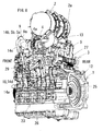
- Figs. 1 to 8 are diagrams for describing an engine according to a first embodiment of the present invention
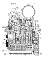
- Figs. 9 to 15 are diagrams for describing an engine according to a second embodiment of the invention. In these embodiments, water-cooling vertical type straight multicylinder diesel engines will be described.
- the first embodiment will be described.
- a general outline of an engine body is as follows.
- a cylinder head (15) is assembled into an upper portion of a cylinder block (23)
- a cylinder head cover (16) is assembled into an upper portion of the cylinder head (15)
- a water pump case (24) is assembled into a front portion of the cylinder block (23)
- a flywheel housing (25) is placed on a rear portion of the cylinder block (23)
- a flywheel (12) is accommodated in the flywheel housing (25)
- an oil pan (26) is assembled into a lower portion of the cylinder block (23).
- An exhaust manifold (6) is assembled into one of lateral sides of the cylinder head (15), and an intake manifold (7) is assembled into the other lateral side.
- the engine includes an engine body (1), a DPF case (2), a high pressure EGR path (3), a supercharger (4) and a low pressure EGR path (5).
- the high pressure EGR path (3) is interposed between the exhaust manifold (6) and the intake manifold (7).
- An exhaust gas discharge path (8) extends from the DPF case (2), an intake pipe (9) extends from an air compressor (4a) of the supercharger (4), the low pressure EGR path (5) is interposed between the exhaust gas discharge path (8) and the intake pipe (9) of the DPF case (2), and the low pressure EGR path (5) is provided with a low pressure EGR cooler (10).
- the engine body (1) is provided with the DPF case (2).
- An extending direction of a crankshaft (11) is defined as a longitudinal direction
- the flywheel (12) is defined as being on a rear side
- a width direction of the engine body (1) is defined as a lateral direction.
- the low pressure EGR path (5) includes a rear path portion (13) extending along a rear side of the engine body (1), and a side path portion (14) extending along a lateral side of the engine body (1) on the side of the exhaust manifold (6).
- the engine body (1) is provided with the DPF case (2) and the engine has a compact shape
- a path length of the low pressure EGR path (5) can be made long by the rear path portion (13) and the side path portion (14)
- radiation performance from portions of the engine other than the low pressure EGR cooler (10) is enhanced, a degree of radiation dependence on the low pressure EGR cooler (10) can be lowered, and it is possible to downsize the low pressure EGR cooler (10).
- the low pressure EGR cooler (10) is placed on the side path portion (14) of the low pressure EGR path (5) at a position lower than an upper surface (15a) of the cylinder head (15).
- a portion close to a start end (start end-close portion, hereinafter) (13a) of the rear path portion (13) of the low pressure EGR path (5) is placed right behind the cylinder head cover (16), a portion close to a terminal end (terminal end-close portion, hereinafter) (13b) of the rear path portion (13) is bent downward from the start end-close portion (13a), and a terminal end (13c) of the rear path portion (13) is connected to the low pressure EGR cooler (10).
- a path length of the rear path portion (13) becomes long by bending the terminal end-close portion (13b), radiation performance of the rear path portion (13) is enhanced, the degree of radiation dependence on the low pressure EGR cooler (10) can be lowered, and it is possible to downsize the low pressure EGR cooler (10).
- engine cooling water which passes through a cooling water jacket of the cylinder head (15) is used as refrigerant of the low pressure EGR cooler (10) located lower than the cylinder head (15).
- the exhaust gas discharge path (8) extends from the DPF case end (2a) on the side of the intake manifold (7), and the rear path portion (13) of the low pressure EGR path (5) branches off from the exhaust gas discharge path (8) on the side of the intake manifold (7).
- the path length of the rear path portion (13) from the exhaust gas discharge path (8) on the side of the intake manifold (7) to the side path portion (14) on the side of the exhaust manifold (6) becomes long, the radiation performance of the rear path portion (13) is enhanced, the degree of radiation dependence on the low pressure EGR cooler (10) can be lowered, and it is possible to downsize the low pressure EGR cooler (10).
- the DPF case (2) is placed above the engine body (1), and a portion of the side path portion (14) of the low pressure EGR path (5) is placed at a position overlapping with the DPF case (2) as viewed from directly above.
- the portion of the side path portion (14) does not largely project laterally more than the DPF case (2), and an entire width of the engine can be kept short.
- the supercharger (4) is mounted on the exhaust manifold (6), and a portion of the side path portion (14) of the low pressure EGR path (5) is placed at a position overlapping with the supercharger (4) as viewed from directly above.
- the portion of the side path portion (14) does not largely project laterally more than the supercharger, and the entire width of the engine can be kept short.
- the side path portion (14) of the low pressure EGR path (5) includes a downward convex bypass path portion (14a) which once moves downward and then moves upward.
- An upper side terminal end (14b) of the downward convex bypass path portion (14a) is connected to the intake pipe (9).
- a path length of the side path portion (14) becomes long by the downward convex bypass path portion (14a), the degree of radiation dependence on the low pressure EGR cooler (10) can be lowered, and it is possible to downsize the low pressure EGR cooler (10).
- the low pressure EGR cooler (10) is placed upstream of the downward convex bypass path portion (14a)
- the low pressure EGR valve case (17) is placed downstream of the downward convex bypass path portion (14a)
- a lowest portion (14d) of the downward convex bypass path portion (14a) is a condensed water reservoir (18) of condensed water which flows out from the low pressure EGR cooler (10) and the low pressure EGR valve case (17).
- condensed water including sulfuric acid component is less prone to stay in the low pressure EGR cooler (10) and the low pressure EGR valve case (17), and it is possible to retard corrosion in the low pressure EGR cooler (10) and the low pressure EGR valve case (17).
- the condensed water reservoir (18) is placed in a lower portion of the low pressure EGR valve case (17). According to this, condensed water including sulfuric acid component does not accumulate in the low pressure EGR valve case (17), and it is possible to retard corrosion in the low pressure EGR valve case (17) and an EGR valve (17a).
- the low pressure EGR valve case (17) is oriented in a direction extending along a horizontal direction
- a valve stem (17b) of the EGR valve (17a) is also oriented in a direction extending along the horizontal direction. According to this, there is no deficiency that condensed water including sulfuric acid component is guided to the valve head (17d) of the EGR valve (17a) along inclinations of the low pressure EGR valve case (17) and the valve stem (17b), and it is possible to retard corrosion of the valve head (17d) of the EGR valve (17a).
- the condensed water reservoir (18) is composed of a cast water saucer. Hence, durability of the condensed water reservoir (18) is high.
- the condensed water reservoir (18) is composed of a cast product of cast iron, a forged product may be used.
- the condensed water reservoir (18) is detachably mounted on the low pressure EGR valve case (17). Hence, maintenance in the low pressure EGR valve case (17) and the EGR valve (17a) and replacement of the EGR valve (17a) are facilitated.
- the condensed water reservoir (18) is mounted on the low pressure EGR valve case (17) through a bolt.
- the lowest portion (14d) of the downward convex bypass path portion (14a) is placed at a position lower than the exhaust manifold (6).
- the supercharger (4) is placed on an upper portion of the exhaust manifold (6), the intake pipe (9) includes a diagonally upwardly extending inclined intake pipe portion (9a), and a terminal end (5a) of the low pressure EGR path (5) is connected to the inclined intake pipe portion (9a).
- the path length of the low pressure EGR path (5) becomes long by the diagonally upwardly extending inclined intake pipe portion (9a), radiation performance from portions of the engine other than the low pressure EGR cooler (10) is enhanced, a degree of radiation dependence on the low pressure EGR cooler (10) can be lowered, and it is possible to downsize the low pressure EGR cooler (10).
- a portion of the downward convex bypass path portion (14a) is placed below the supercharger (4) at a position overlapping with the supercharger (4) as viewed from directly above.
- the portion of the downward convex bypass path portion (14a) does not largely project laterally more than the supercharger (4), and the entire width of the engine can be kept short.
- a portion of the downward convex bypass path portion (14a) is placed below the intake pipe (9) at a position overlapping with the intake pipe (9) as viewed from directly above.
- the portion of the downward convex bypass path portion (14a) does not largely project laterally more than the intake pipe (9), and the entire width of the engine can be kept short.
- the terminal end (5a) of the low pressure EGR path (5) is provided with the low pressure EGR outlet (5b) which opens at the intake pipe (9)
- a terminal end (19a) of a blow-by gas passage (19) is provided with a blow-by gas outlet (19b) which opens at the intake pipe (9)
- the low pressure EGR outlet (5b) and the blow-by gas outlet (19b) are placed at positions where they are opposed to each other while sandwiching a passage (9b) in the intake pipe (9) therebetween.
- low pressure EGR gas (20) flows out from the low pressure EGR outlet (5b) toward the blow-by gas outlet (19b).
- the blow-by gas outlet (19b) is heated by heat of the low pressure EGR gas (20), and it is possible to prevent freezing of the blow-by gas outlet (19b) when it is cold.
- the laterally oriented low pressure EGR outlet (5b) is placed in a lateral peripheral wall (9f) of the intake pipe (9).
- the laterally oriented blow-by gas outlet (19b) is placed in another lateral peripheral wall (9f) of the intake pipe (9) which is opposed to the low pressure EGR outlet (5b).
- an exhaust gas discharge pipe (2b) of the DPF case (2) which configures a start end of the exhaust gas discharge path (8) and which makes the rear path portion (13) of the low pressure EGR path (5) branch off inclines in a direction separating away from the exhaust manifold (6).
- the path length of the rear path portion (13) becomes long, the radiation performance of the rear path portion (13) is enhanced, the degree of radiation dependence on the low pressure EGR cooler (10) can be lowered, and it is possible to downsize the low pressure EGR cooler (10).
- An exhaust duct (not shown) configuring the exhaust gas discharge path (8) is connected to a tip end of the exhaust gas discharge pipe (2b), and an SCR catalyst case is connected to a tip end of the exhaust duct.
- a DOC (32) is placed on an upstream side and a DPF (33) is placed on a downstream side.
- the DOC is a Diesel Oxidation Catalyst and the DPF is a Diesel Particulate Filter.
- SCR is a Selective Catalytic Reduction of NOx.
- the high pressure EGR path (3) includes a rear high pressure EGR cooler (27) existing right behind the cylinder head (15), and a side high pressure EGR cooler (28) existing right beside the cylinder head (15). Both the rear high pressure EGR cooler (27) and the side high pressure EGR cooler (28) are placed at positions lower than the upper surface (15a) of the cylinder head (15), and engine cooling water passing through the cooling water jacket of the cylinder head (15) is used as refrigerant.
- a pipe portion of the high pressure EGR path (3) that does not include the rear high pressure EGR cooler (27) and the side high pressure EGR cooler (28), and a pipe portion of the low pressure EGR path (5) that does not include the low pressure EGR cooler (10) and the low pressure EGR valve case (17) are composed of metal pipes which easily release heat.
- the EGR valve (17a) is accommodated in the low pressure EGR valve case (17) shown in Fig. 3 , and a periphery of the valve stem (17b) is sealed by a stem seal (17c).
- a valve actuator (29) is mounted on a front side of the EGR valve case (17), and the EGR valve (17a) is opened and closed by the valve actuator (29).
- an intermediate portion of the blow-by gas passage (19) is provided with an oil separator (19c).
- the oil separator (19c) is placed directly above the cylinder head cover (16).
- a common rail system (30) and an electronic throttle device (31) are placed on the engine body on the side of the intake manifold (7).
- the electronic throttle device (31) is placed directly above the intake manifold (7).
- a second embodiment is different from the first embodiment in the following points. Other points of the second embodiment are the same as those of the first embodiment.
- Figs. 9 to 15 the same reference signs are allocated to the same elements as those in the first embodiment shown in Figs. 1 to 8 .
- a DPF case (2) is placed above an engine body (1).
- An exhaust gas discharge path (8) and a rear path portion (13) of a low pressure EGR path (5) are placed below the DPF case (2) at positions overlapping with the DPF case (2) as viewed from directly above.
- the exhaust gas discharge path (8) and the rear path portion (13) of the low pressure EGR path (5) do not largely project rearward more than the DPF case (2), and an entire length of an engine can be kept short.
- a high pressure EGR path (3) is placed below the DPF case (2) at a position overlapping with the DPF case (2) as viewed from directly above.
- the high pressure EGR path (3) does not largely project rearward and laterally more than the DPF case (2), and an entire length and an entire width of the engine can be kept short.
- a low pressure EGR valve case (17) inclines downward toward a condensed water reservoir (18).
- condensed water (21) including sulfuric acid component is less prone to stay in the low pressure EGR valve case (17), and it is possible to retard corrosion in the low pressure EGR valve case (17).
- the low pressure EGR valve case (17) is placed on a lower bypass path portion (14a).
- An EGR valve (17a), a valve stem (17b) and a stem seal (17c) incline downward toward the condensed water reservoir (18) like the low pressure EGR valve case (17).
- a valve actuator (29) also inclines downward toward the condensed water reservoir (18) like the low pressure EGR valve case (17).
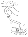
- a rising path portion (14c) of a downward convex bypass path portion (14a) bends along a shape of an intake pipe (9).
- a path length of the rising path portion (14c) becomes long by the bent shape, radiation performance from portions of the engine other than the low pressure EGR cooler (10) is enhanced, a degree of radiation dependence on the low pressure EGR cooler (10) can be lowered, and it is possible to downsize the low pressure EGR cooler (10).
- the intake pipe (9) includes a diagonally upwardly extending inclined intake pipe portion (9a), a low pressure EGR outlet (5b) is placed in a lower peripheral wall (9c) of the inclined intake pipe portion (9a), and a blow-by gas outlet (19b) is placed in an upper peripheral wall (9d) of the inclined intake pipe portion (9a).
- the low pressure EGR outlet (5b) is placed at a position higher than a directly-below position (9e) of the lower peripheral wall (9c), the directly-below position (9e) being located directly below the blow-by gas outlet (19b).
Landscapes
- Engineering & Computer Science (AREA)
- Chemical & Material Sciences (AREA)
- Combustion & Propulsion (AREA)
- Mechanical Engineering (AREA)
- General Engineering & Computer Science (AREA)
- Chemical Kinetics & Catalysis (AREA)
- Exhaust-Gas Circulating Devices (AREA)
- Exhaust Gas After Treatment (AREA)
- Processes For Solid Components From Exhaust (AREA)
Applications Claiming Priority (2)
| Application Number | Priority Date | Filing Date | Title |
|---|---|---|---|
| JP2013199222 | 2013-09-26 | ||
| JP2014074652A JP6163447B2 (ja) | 2013-09-26 | 2014-03-31 | エンジン |
Publications (3)
| Publication Number | Publication Date |
|---|---|
| EP2853726A2 true EP2853726A2 (fr) | 2015-04-01 |
| EP2853726A3 EP2853726A3 (fr) | 2016-01-20 |
| EP2853726B1 EP2853726B1 (fr) | 2017-03-29 |
Family
ID=51265571
Family Applications (1)
| Application Number | Title | Priority Date | Filing Date |
|---|---|---|---|
| EP14179702.7A Active EP2853726B1 (fr) | 2013-09-26 | 2014-08-04 | Moteur |
Country Status (3)
| Country | Link |
|---|---|
| US (1) | US9670883B2 (fr) |
| EP (1) | EP2853726B1 (fr) |
| JP (1) | JP6163447B2 (fr) |
Cited By (3)
| Publication number | Priority date | Publication date | Assignee | Title |
|---|---|---|---|---|
| FR3039856A1 (fr) * | 2015-08-03 | 2017-02-10 | Peugeot Citroen Automobiles Sa | Canalisation chauffee de recyclage des gaz de carter |
| CN108626042A (zh) * | 2017-03-16 | 2018-10-09 | 铃木株式会社 | 内燃机的进气装置 |
| IT202300015042A1 (it) * | 2023-07-18 | 2025-01-18 | Stellantis Europe Spa | "motore a combustione interna per autoveicoli" |
Families Citing this family (6)
| Publication number | Priority date | Publication date | Assignee | Title |
|---|---|---|---|---|
| CN106499549B (zh) * | 2016-11-30 | 2018-09-11 | 安徽江淮汽车集团股份有限公司 | 一种egr导流管结构 |
| DE102017204897A1 (de) * | 2017-03-23 | 2018-09-27 | Volkswagen Aktiengesellschaft | Verbrennungsmotor und Abgasnachbehandlungssystem für einen Verbrennungsmotor |
| JP6437597B1 (ja) * | 2017-06-16 | 2018-12-12 | 本田技研工業株式会社 | 内燃機関 |
| JP6850250B2 (ja) * | 2017-12-28 | 2021-03-31 | 株式会社クボタ | Egr付エンジン |
| JP7043849B2 (ja) * | 2018-01-26 | 2022-03-30 | マツダ株式会社 | エンジンの吸排気装置 |
| EP4311929A1 (fr) | 2022-07-26 | 2024-01-31 | Winterthur Gas & Diesel Ltd. | Dispositif de refroidissement de gaz d'échappement |
Citations (1)
| Publication number | Priority date | Publication date | Assignee | Title |
|---|---|---|---|---|
| JP2007146774A (ja) | 2005-11-29 | 2007-06-14 | Nissan Diesel Motor Co Ltd | Egrシステム |
Family Cites Families (32)
| Publication number | Priority date | Publication date | Assignee | Title |
|---|---|---|---|---|
| US6138649A (en) * | 1997-09-22 | 2000-10-31 | Southwest Research Institute | Fast acting exhaust gas recirculation system |
| JP2000087808A (ja) * | 1998-09-10 | 2000-03-28 | Yamaha Motor Co Ltd | 筒内噴射式エンジン |
| JP2000248936A (ja) * | 1999-03-02 | 2000-09-12 | Nissan Motor Co Ltd | 内燃機関の排気還流装置 |
| JP2002188526A (ja) * | 2000-12-20 | 2002-07-05 | Hino Motors Ltd | Egr装置 |
| JP2003220465A (ja) * | 2002-01-24 | 2003-08-05 | Aichi Mach Ind Co Ltd | フランジに対する配管の接合構造 |
| KR100845284B1 (ko) * | 2004-09-22 | 2008-07-09 | 삼성전자주식회사 | 두개의 닙코우 디스크를 이용한 공초점 주사 현미경 |
| DE102005002266A1 (de) * | 2005-01-18 | 2006-07-20 | Bayerische Motoren Werke Ag | Abgasrückführsystem für eine Brennkraftmaschine |
| JP4411261B2 (ja) * | 2005-09-21 | 2010-02-10 | 株式会社クボタ | 多気筒エンジン |
| JP4411263B2 (ja) * | 2005-09-26 | 2010-02-10 | 株式会社クボタ | 多気筒エンジン |
| JP4551852B2 (ja) * | 2005-09-28 | 2010-09-29 | 株式会社クボタ | 多気筒エンジン |
| JP2007092706A (ja) * | 2005-09-30 | 2007-04-12 | Kubota Corp | エンジン |
| JP2008014232A (ja) * | 2006-07-06 | 2008-01-24 | Yanmar Co Ltd | エンジンの排気ガス再循環装置 |
| US8388712B2 (en) * | 2009-02-12 | 2013-03-05 | Ford Global Technologies, Llc | Particulate matter retaining and purging system |
| JP5782219B2 (ja) * | 2009-03-16 | 2015-09-24 | ヤンマー株式会社 | エンジン装置 |
| JP5443027B2 (ja) * | 2009-03-16 | 2014-03-19 | ヤンマー株式会社 | エンジン装置 |
| JP5390281B2 (ja) * | 2009-07-02 | 2014-01-15 | ヤンマー株式会社 | 排気ガス浄化装置 |
| JP5393375B2 (ja) * | 2009-09-24 | 2014-01-22 | ダイハツ工業株式会社 | 内燃機関 |
| US8181452B2 (en) * | 2009-09-29 | 2012-05-22 | Ford Global Technologies, Llc | Particulate filter regeneration during engine shutdown |
| US8407988B2 (en) * | 2009-09-29 | 2013-04-02 | Ford Global Technologies, Llc | Particulate filter regeneration in an engine coupled to an energy conversion device |
| US8096125B2 (en) * | 2009-12-23 | 2012-01-17 | Ford Global Technologies, Llc | Methods and systems for emission system control |
| US8347611B2 (en) * | 2009-12-23 | 2013-01-08 | Ford Global Technologies, Llc | Methods and systems for emission system control |
| JP5616194B2 (ja) * | 2010-01-14 | 2014-10-29 | 株式会社クボタ | 排気処理装置付きエンジン |
| US8516816B2 (en) * | 2010-06-02 | 2013-08-27 | Ford Global Technologies, Llc | Avoidance of coolant overheating in exhaust-to-coolant heat exchangers |
| EP2397677B1 (fr) * | 2010-06-16 | 2018-10-17 | Honda Motor Co., Ltd. | Appareil de contrôle de recyclage des gaz d'échappement pour moteur à combustion interne |
| JP5028509B2 (ja) * | 2010-06-16 | 2012-09-19 | 本田技研工業株式会社 | 内燃機関のegr制御装置 |
| JP5381937B2 (ja) * | 2010-09-08 | 2014-01-08 | マツダ株式会社 | 車両の排気系装置 |
| JP2012127261A (ja) * | 2010-12-15 | 2012-07-05 | Ud Trucks Corp | 多気筒エンジンのegr装置 |
| JP5881983B2 (ja) * | 2011-07-07 | 2016-03-09 | ヤンマー株式会社 | エンジンの排気再循環装置 |
| DE102011111590A1 (de) * | 2011-08-25 | 2013-02-28 | Volkswagen Aktiengesellschaft | Abgasbehandlungseinrichtung, Verfahren zur Aufbereitung von Abgas und Kraftfahrzeug |
| JP5537538B2 (ja) * | 2011-12-22 | 2014-07-02 | ヤンマー株式会社 | 排気ガス浄化装置 |
| US9297338B2 (en) * | 2013-05-08 | 2016-03-29 | Ford Global Technologies, Llc | Diesel particulate filter passive regeneration during stationary power take-off |
| JP2014040836A (ja) * | 2013-09-30 | 2014-03-06 | Yanmar Co Ltd | エンジン装置 |
-
2014
- 2014-03-31 JP JP2014074652A patent/JP6163447B2/ja active Active
- 2014-08-04 EP EP14179702.7A patent/EP2853726B1/fr active Active
- 2014-08-08 US US14/455,421 patent/US9670883B2/en active Active
Patent Citations (1)
| Publication number | Priority date | Publication date | Assignee | Title |
|---|---|---|---|---|
| JP2007146774A (ja) | 2005-11-29 | 2007-06-14 | Nissan Diesel Motor Co Ltd | Egrシステム |
Cited By (4)
| Publication number | Priority date | Publication date | Assignee | Title |
|---|---|---|---|---|
| FR3039856A1 (fr) * | 2015-08-03 | 2017-02-10 | Peugeot Citroen Automobiles Sa | Canalisation chauffee de recyclage des gaz de carter |
| CN108626042A (zh) * | 2017-03-16 | 2018-10-09 | 铃木株式会社 | 内燃机的进气装置 |
| CN108626042B (zh) * | 2017-03-16 | 2020-10-16 | 铃木株式会社 | 内燃机的进气装置 |
| IT202300015042A1 (it) * | 2023-07-18 | 2025-01-18 | Stellantis Europe Spa | "motore a combustione interna per autoveicoli" |
Also Published As
| Publication number | Publication date |
|---|---|
| JP2015086857A (ja) | 2015-05-07 |
| EP2853726B1 (fr) | 2017-03-29 |
| US20150082772A1 (en) | 2015-03-26 |
| JP6163447B2 (ja) | 2017-07-12 |
| US9670883B2 (en) | 2017-06-06 |
| EP2853726A3 (fr) | 2016-01-20 |
Similar Documents
| Publication | Publication Date | Title |
|---|---|---|
| EP2853726B1 (fr) | Moteur | |
| EP1770272A2 (fr) | Moteur à combustion interne multicylindres | |
| RU140416U1 (ru) | Воздуховод охладителя наддувочного воздуха (варианты) | |
| EP3517767B1 (fr) | Système d'admission et d'échappement de moteur et moteur équipé d'un tel système | |
| JP2014109259A (ja) | 凝縮水循環システム | |
| JP6051136B2 (ja) | エンジン | |
| EP3263859B1 (fr) | Système de commande de gaz d'échappement pour moteur à combustion interne | |
| JP4600168B2 (ja) | エンジンのegr冷却装置配設構造 | |
| JP6477615B2 (ja) | 排気浄化システムの冷却装置 | |
| EP3517768A1 (fr) | Système d'admission et d'échappement de moteur, moteur équipé d'un tel système et son procédé de production | |
| JP6270594B2 (ja) | エンジン | |
| JP6407770B2 (ja) | エンジン | |
| JP2012067696A (ja) | インテークパイプ | |
| EP3985234B1 (fr) | Dispositif de recirculation de gaz de fuyage | |
| JP6350804B2 (ja) | 内燃機関の吸気装置 | |
| EP3517769B1 (fr) | Système d'admission et d'échappement de moteur et moteur à combustion interne | |
| JP7103928B2 (ja) | ブローバイガス還流装置 | |
| JP2016125452A (ja) | 内燃機関 | |
| JP2010156272A (ja) | 内燃機関のegr装置及びegrフィルタ | |
| RU2016148326A (ru) | Работающий на отработавших газах турбонагнетатель для автомобиля | |
| CN220415492U (zh) | 一种曲轴箱通风系统及发动机总成 | |
| JP5709452B2 (ja) | 内燃機関 | |
| US9316186B2 (en) | Engine intake with sump having a heat source | |
| DE102018112695A1 (de) | Niederdruck-AGR-Vorrichtung für eine Brennkraftmaschine. | |
| EP2719885A1 (fr) | Agencement de refroidissement des gaz d'échappement dans un moteur à combustion interne |
Legal Events
| Date | Code | Title | Description |
|---|---|---|---|
| PUAI | Public reference made under article 153(3) epc to a published international application that has entered the european phase |
Free format text: ORIGINAL CODE: 0009012 |
|
| 17P | Request for examination filed |
Effective date: 20140804 |
|
| AK | Designated contracting states |
Kind code of ref document: A2 Designated state(s): AL AT BE BG CH CY CZ DE DK EE ES FI FR GB GR HR HU IE IS IT LI LT LU LV MC MK MT NL NO PL PT RO RS SE SI SK SM TR |
|
| AX | Request for extension of the european patent |
Extension state: BA ME |
|
| PUAL | Search report despatched |
Free format text: ORIGINAL CODE: 0009013 |
|
| AK | Designated contracting states |
Kind code of ref document: A3 Designated state(s): AL AT BE BG CH CY CZ DE DK EE ES FI FR GB GR HR HU IE IS IT LI LT LU LV MC MK MT NL NO PL PT RO RS SE SI SK SM TR |
|
| AX | Request for extension of the european patent |
Extension state: BA ME |
|
| RIC1 | Information provided on ipc code assigned before grant |
Ipc: F02M 35/10 20060101ALN20151211BHEP Ipc: F02M 25/07 00000000AFI20151211BHEP Ipc: F02M 25/06 20060101ALN20151211BHEP |
|
| R17P | Request for examination filed (corrected) |
Effective date: 20160518 |
|
| RBV | Designated contracting states (corrected) |
Designated state(s): AL AT BE BG CH CY CZ DE DK EE ES FI FR GB GR HR HU IE IS IT LI LT LU LV MC MK MT NL NO PL PT RO RS SE SI SK SM TR |
|
| REG | Reference to a national code |
Ref country code: DE Ref legal event code: R079 Ref document number: 602014008008 Country of ref document: DE Free format text: PREVIOUS MAIN CLASS: F02M0025070000 Ipc: F02M0026050000 |
|
| RIC1 | Information provided on ipc code assigned before grant |
Ipc: F02M 26/24 20160101ALI20161013BHEP Ipc: F02M 26/32 20160101ALI20161013BHEP Ipc: F02M 25/06 20060101ALN20161013BHEP Ipc: F02M 26/28 20160101ALI20161013BHEP Ipc: F02M 26/05 20160101AFI20161013BHEP Ipc: F02M 26/35 20160101ALI20161013BHEP Ipc: F02M 26/06 20160101ALI20161013BHEP Ipc: F02M 26/12 20160101ALI20161013BHEP Ipc: F02M 35/10 20060101ALN20161013BHEP Ipc: F02M 26/15 20160101ALI20161013BHEP |
|
| GRAP | Despatch of communication of intention to grant a patent |
Free format text: ORIGINAL CODE: EPIDOSNIGR1 |
|
| INTG | Intention to grant announced |
Effective date: 20161121 |
|
| GRAS | Grant fee paid |
Free format text: ORIGINAL CODE: EPIDOSNIGR3 |
|
| GRAA | (expected) grant |
Free format text: ORIGINAL CODE: 0009210 |
|
| AK | Designated contracting states |
Kind code of ref document: B1 Designated state(s): AL AT BE BG CH CY CZ DE DK EE ES FI FR GB GR HR HU IE IS IT LI LT LU LV MC MK MT NL NO PL PT RO RS SE SI SK SM TR |
|
| REG | Reference to a national code |
Ref country code: GB Ref legal event code: FG4D |
|
| REG | Reference to a national code |
Ref country code: CH Ref legal event code: EP |
|
| REG | Reference to a national code |
Ref country code: AT Ref legal event code: REF Ref document number: 880017 Country of ref document: AT Kind code of ref document: T Effective date: 20170415 |
|
| REG | Reference to a national code |
Ref country code: IE Ref legal event code: FG4D |
|
| REG | Reference to a national code |
Ref country code: DE Ref legal event code: R096 Ref document number: 602014008008 Country of ref document: DE |
|
| REG | Reference to a national code |
Ref country code: FR Ref legal event code: PLFP Year of fee payment: 4 |
|
| PG25 | Lapsed in a contracting state [announced via postgrant information from national office to epo] |
Ref country code: GR Free format text: LAPSE BECAUSE OF FAILURE TO SUBMIT A TRANSLATION OF THE DESCRIPTION OR TO PAY THE FEE WITHIN THE PRESCRIBED TIME-LIMIT Effective date: 20170630 Ref country code: LT Free format text: LAPSE BECAUSE OF FAILURE TO SUBMIT A TRANSLATION OF THE DESCRIPTION OR TO PAY THE FEE WITHIN THE PRESCRIBED TIME-LIMIT Effective date: 20170329 Ref country code: HR Free format text: LAPSE BECAUSE OF FAILURE TO SUBMIT A TRANSLATION OF THE DESCRIPTION OR TO PAY THE FEE WITHIN THE PRESCRIBED TIME-LIMIT Effective date: 20170329 Ref country code: NO Free format text: LAPSE BECAUSE OF FAILURE TO SUBMIT A TRANSLATION OF THE DESCRIPTION OR TO PAY THE FEE WITHIN THE PRESCRIBED TIME-LIMIT Effective date: 20170629 Ref country code: FI Free format text: LAPSE BECAUSE OF FAILURE TO SUBMIT A TRANSLATION OF THE DESCRIPTION OR TO PAY THE FEE WITHIN THE PRESCRIBED TIME-LIMIT Effective date: 20170329 |
|
| REG | Reference to a national code |
Ref country code: NL Ref legal event code: MP Effective date: 20170329 |
|
| REG | Reference to a national code |
Ref country code: AT Ref legal event code: MK05 Ref document number: 880017 Country of ref document: AT Kind code of ref document: T Effective date: 20170329 |
|
| PG25 | Lapsed in a contracting state [announced via postgrant information from national office to epo] |
Ref country code: LV Free format text: LAPSE BECAUSE OF FAILURE TO SUBMIT A TRANSLATION OF THE DESCRIPTION OR TO PAY THE FEE WITHIN THE PRESCRIBED TIME-LIMIT Effective date: 20170329 Ref country code: RS Free format text: LAPSE BECAUSE OF FAILURE TO SUBMIT A TRANSLATION OF THE DESCRIPTION OR TO PAY THE FEE WITHIN THE PRESCRIBED TIME-LIMIT Effective date: 20170329 Ref country code: BG Free format text: LAPSE BECAUSE OF FAILURE TO SUBMIT A TRANSLATION OF THE DESCRIPTION OR TO PAY THE FEE WITHIN THE PRESCRIBED TIME-LIMIT Effective date: 20170629 Ref country code: SE Free format text: LAPSE BECAUSE OF FAILURE TO SUBMIT A TRANSLATION OF THE DESCRIPTION OR TO PAY THE FEE WITHIN THE PRESCRIBED TIME-LIMIT Effective date: 20170329 |
|
| PG25 | Lapsed in a contracting state [announced via postgrant information from national office to epo] |
Ref country code: NL Free format text: LAPSE BECAUSE OF FAILURE TO SUBMIT A TRANSLATION OF THE DESCRIPTION OR TO PAY THE FEE WITHIN THE PRESCRIBED TIME-LIMIT Effective date: 20170329 |
|
| PG25 | Lapsed in a contracting state [announced via postgrant information from national office to epo] |
Ref country code: CZ Free format text: LAPSE BECAUSE OF FAILURE TO SUBMIT A TRANSLATION OF THE DESCRIPTION OR TO PAY THE FEE WITHIN THE PRESCRIBED TIME-LIMIT Effective date: 20170329 Ref country code: IT Free format text: LAPSE BECAUSE OF FAILURE TO SUBMIT A TRANSLATION OF THE DESCRIPTION OR TO PAY THE FEE WITHIN THE PRESCRIBED TIME-LIMIT Effective date: 20170329 Ref country code: AT Free format text: LAPSE BECAUSE OF FAILURE TO SUBMIT A TRANSLATION OF THE DESCRIPTION OR TO PAY THE FEE WITHIN THE PRESCRIBED TIME-LIMIT Effective date: 20170329 Ref country code: SK Free format text: LAPSE BECAUSE OF FAILURE TO SUBMIT A TRANSLATION OF THE DESCRIPTION OR TO PAY THE FEE WITHIN THE PRESCRIBED TIME-LIMIT Effective date: 20170329 Ref country code: EE Free format text: LAPSE BECAUSE OF FAILURE TO SUBMIT A TRANSLATION OF THE DESCRIPTION OR TO PAY THE FEE WITHIN THE PRESCRIBED TIME-LIMIT Effective date: 20170329 Ref country code: RO Free format text: LAPSE BECAUSE OF FAILURE TO SUBMIT A TRANSLATION OF THE DESCRIPTION OR TO PAY THE FEE WITHIN THE PRESCRIBED TIME-LIMIT Effective date: 20170329 Ref country code: ES Free format text: LAPSE BECAUSE OF FAILURE TO SUBMIT A TRANSLATION OF THE DESCRIPTION OR TO PAY THE FEE WITHIN THE PRESCRIBED TIME-LIMIT Effective date: 20170329 |
|
| PG25 | Lapsed in a contracting state [announced via postgrant information from national office to epo] |
Ref country code: IS Free format text: LAPSE BECAUSE OF FAILURE TO SUBMIT A TRANSLATION OF THE DESCRIPTION OR TO PAY THE FEE WITHIN THE PRESCRIBED TIME-LIMIT Effective date: 20170729 Ref country code: PT Free format text: LAPSE BECAUSE OF FAILURE TO SUBMIT A TRANSLATION OF THE DESCRIPTION OR TO PAY THE FEE WITHIN THE PRESCRIBED TIME-LIMIT Effective date: 20170731 Ref country code: PL Free format text: LAPSE BECAUSE OF FAILURE TO SUBMIT A TRANSLATION OF THE DESCRIPTION OR TO PAY THE FEE WITHIN THE PRESCRIBED TIME-LIMIT Effective date: 20170329 Ref country code: SM Free format text: LAPSE BECAUSE OF FAILURE TO SUBMIT A TRANSLATION OF THE DESCRIPTION OR TO PAY THE FEE WITHIN THE PRESCRIBED TIME-LIMIT Effective date: 20170329 |
|
| REG | Reference to a national code |
Ref country code: DE Ref legal event code: R097 Ref document number: 602014008008 Country of ref document: DE |
|
| PG25 | Lapsed in a contracting state [announced via postgrant information from national office to epo] |
Ref country code: DK Free format text: LAPSE BECAUSE OF FAILURE TO SUBMIT A TRANSLATION OF THE DESCRIPTION OR TO PAY THE FEE WITHIN THE PRESCRIBED TIME-LIMIT Effective date: 20170329 |
|
| PLBE | No opposition filed within time limit |
Free format text: ORIGINAL CODE: 0009261 |
|
| STAA | Information on the status of an ep patent application or granted ep patent |
Free format text: STATUS: NO OPPOSITION FILED WITHIN TIME LIMIT |
|
| 26N | No opposition filed |
Effective date: 20180103 |
|
| REG | Reference to a national code |
Ref country code: CH Ref legal event code: PL |
|
| PG25 | Lapsed in a contracting state [announced via postgrant information from national office to epo] |
Ref country code: MC Free format text: LAPSE BECAUSE OF FAILURE TO SUBMIT A TRANSLATION OF THE DESCRIPTION OR TO PAY THE FEE WITHIN THE PRESCRIBED TIME-LIMIT Effective date: 20170329 |
|
| PG25 | Lapsed in a contracting state [announced via postgrant information from national office to epo] |
Ref country code: CH Free format text: LAPSE BECAUSE OF NON-PAYMENT OF DUE FEES Effective date: 20170831 Ref country code: LI Free format text: LAPSE BECAUSE OF NON-PAYMENT OF DUE FEES Effective date: 20170831 |
|
| REG | Reference to a national code |
Ref country code: IE Ref legal event code: MM4A |
|
| PG25 | Lapsed in a contracting state [announced via postgrant information from national office to epo] |
Ref country code: SI Free format text: LAPSE BECAUSE OF FAILURE TO SUBMIT A TRANSLATION OF THE DESCRIPTION OR TO PAY THE FEE WITHIN THE PRESCRIBED TIME-LIMIT Effective date: 20170329 |
|
| REG | Reference to a national code |
Ref country code: BE Ref legal event code: MM Effective date: 20170831 |
|
| PG25 | Lapsed in a contracting state [announced via postgrant information from national office to epo] |
Ref country code: LU Free format text: LAPSE BECAUSE OF NON-PAYMENT OF DUE FEES Effective date: 20170804 |
|
| REG | Reference to a national code |
Ref country code: FR Ref legal event code: PLFP Year of fee payment: 5 |
|
| PG25 | Lapsed in a contracting state [announced via postgrant information from national office to epo] |
Ref country code: IE Free format text: LAPSE BECAUSE OF NON-PAYMENT OF DUE FEES Effective date: 20170804 |
|
| PG25 | Lapsed in a contracting state [announced via postgrant information from national office to epo] |
Ref country code: BE Free format text: LAPSE BECAUSE OF NON-PAYMENT OF DUE FEES Effective date: 20170831 |
|
| PG25 | Lapsed in a contracting state [announced via postgrant information from national office to epo] |
Ref country code: MT Free format text: LAPSE BECAUSE OF NON-PAYMENT OF DUE FEES Effective date: 20170804 |
|
| PG25 | Lapsed in a contracting state [announced via postgrant information from national office to epo] |
Ref country code: HU Free format text: LAPSE BECAUSE OF FAILURE TO SUBMIT A TRANSLATION OF THE DESCRIPTION OR TO PAY THE FEE WITHIN THE PRESCRIBED TIME-LIMIT; INVALID AB INITIO Effective date: 20140804 |
|
| PG25 | Lapsed in a contracting state [announced via postgrant information from national office to epo] |
Ref country code: CY Free format text: LAPSE BECAUSE OF FAILURE TO SUBMIT A TRANSLATION OF THE DESCRIPTION OR TO PAY THE FEE WITHIN THE PRESCRIBED TIME-LIMIT Effective date: 20170329 |
|
| PG25 | Lapsed in a contracting state [announced via postgrant information from national office to epo] |
Ref country code: MK Free format text: LAPSE BECAUSE OF FAILURE TO SUBMIT A TRANSLATION OF THE DESCRIPTION OR TO PAY THE FEE WITHIN THE PRESCRIBED TIME-LIMIT Effective date: 20170329 |
|
| PG25 | Lapsed in a contracting state [announced via postgrant information from national office to epo] |
Ref country code: TR Free format text: LAPSE BECAUSE OF FAILURE TO SUBMIT A TRANSLATION OF THE DESCRIPTION OR TO PAY THE FEE WITHIN THE PRESCRIBED TIME-LIMIT Effective date: 20170329 |
|
| PG25 | Lapsed in a contracting state [announced via postgrant information from national office to epo] |
Ref country code: AL Free format text: LAPSE BECAUSE OF FAILURE TO SUBMIT A TRANSLATION OF THE DESCRIPTION OR TO PAY THE FEE WITHIN THE PRESCRIBED TIME-LIMIT Effective date: 20170329 |
|
| PGFP | Annual fee paid to national office [announced via postgrant information from national office to epo] |
Ref country code: DE Payment date: 20250702 Year of fee payment: 12 |
|
| PGFP | Annual fee paid to national office [announced via postgrant information from national office to epo] |
Ref country code: GB Payment date: 20250703 Year of fee payment: 12 |
|
| PGFP | Annual fee paid to national office [announced via postgrant information from national office to epo] |
Ref country code: FR Payment date: 20250703 Year of fee payment: 12 |