EP2853738B1 - Mechanisches System, Einspritzpumpe und Ventilaktor mit einem solchen mechanischen System und Herstellungsverfahren - Google Patents
Mechanisches System, Einspritzpumpe und Ventilaktor mit einem solchen mechanischen System und Herstellungsverfahren Download PDFInfo
- Publication number
- EP2853738B1 EP2853738B1 EP13186511.5A EP13186511A EP2853738B1 EP 2853738 B1 EP2853738 B1 EP 2853738B1 EP 13186511 A EP13186511 A EP 13186511A EP 2853738 B1 EP2853738 B1 EP 2853738B1
- Authority
- EP
- European Patent Office
- Prior art keywords
- insert
- mechanical system
- axis
- pin
- along
- Prior art date
- Legal status (The legal status is an assumption and is not a legal conclusion. Google has not performed a legal analysis and makes no representation as to the accuracy of the status listed.)
- Active
Links
Images




Classifications
-
- F—MECHANICAL ENGINEERING; LIGHTING; HEATING; WEAPONS; BLASTING
- F16—ENGINEERING ELEMENTS AND UNITS; GENERAL MEASURES FOR PRODUCING AND MAINTAINING EFFECTIVE FUNCTIONING OF MACHINES OR INSTALLATIONS; THERMAL INSULATION IN GENERAL
- F16H—GEARING
- F16H53/00—Cams or cam-followers, e.g. rollers for gearing mechanisms
- F16H53/06—Cam-followers
-
- F—MECHANICAL ENGINEERING; LIGHTING; HEATING; WEAPONS; BLASTING
- F01—MACHINES OR ENGINES IN GENERAL; ENGINE PLANTS IN GENERAL; STEAM ENGINES
- F01L—CYCLICALLY OPERATING VALVES FOR MACHINES OR ENGINES
- F01L1/00—Valve-gear or valve arrangements, e.g. lift-valve gear
- F01L1/02—Valve drive
- F01L1/04—Valve drive by means of cams, camshafts, cam discs, eccentrics or the like
-
- F—MECHANICAL ENGINEERING; LIGHTING; HEATING; WEAPONS; BLASTING
- F01—MACHINES OR ENGINES IN GENERAL; ENGINE PLANTS IN GENERAL; STEAM ENGINES
- F01L—CYCLICALLY OPERATING VALVES FOR MACHINES OR ENGINES
- F01L1/00—Valve-gear or valve arrangements, e.g. lift-valve gear
- F01L1/12—Transmitting gear between valve drive and valve
- F01L1/14—Tappets; Push rods
-
- F—MECHANICAL ENGINEERING; LIGHTING; HEATING; WEAPONS; BLASTING
- F01—MACHINES OR ENGINES IN GENERAL; ENGINE PLANTS IN GENERAL; STEAM ENGINES
- F01L—CYCLICALLY OPERATING VALVES FOR MACHINES OR ENGINES
- F01L1/00—Valve-gear or valve arrangements, e.g. lift-valve gear
- F01L1/12—Transmitting gear between valve drive and valve
- F01L1/14—Tappets; Push rods
- F01L1/143—Tappets; Push rods for use with overhead camshafts
-
- F—MECHANICAL ENGINEERING; LIGHTING; HEATING; WEAPONS; BLASTING
- F02—COMBUSTION ENGINES; HOT-GAS OR COMBUSTION-PRODUCT ENGINE PLANTS
- F02M—SUPPLYING COMBUSTION ENGINES IN GENERAL WITH COMBUSTIBLE MIXTURES OR CONSTITUENTS THEREOF
- F02M37/00—Apparatus or systems for feeding liquid fuel from storage containers to carburettors or fuel-injection apparatus; Arrangements for purifying liquid fuel specially adapted for, or arranged on, internal-combustion engines
- F02M37/04—Feeding by means of driven pumps
- F02M37/06—Feeding by means of driven pumps mechanically driven
-
- F—MECHANICAL ENGINEERING; LIGHTING; HEATING; WEAPONS; BLASTING
- F02—COMBUSTION ENGINES; HOT-GAS OR COMBUSTION-PRODUCT ENGINE PLANTS
- F02M—SUPPLYING COMBUSTION ENGINES IN GENERAL WITH COMBUSTIBLE MIXTURES OR CONSTITUENTS THEREOF
- F02M59/00—Pumps specially adapted for fuel-injection and not provided for in groups F02M39/00 -F02M57/00, e.g. rotary cylinder-block type of pumps
- F02M59/02—Pumps specially adapted for fuel-injection and not provided for in groups F02M39/00 -F02M57/00, e.g. rotary cylinder-block type of pumps of reciprocating-piston or reciprocating-cylinder type
- F02M59/10—Pumps specially adapted for fuel-injection and not provided for in groups F02M39/00 -F02M57/00, e.g. rotary cylinder-block type of pumps of reciprocating-piston or reciprocating-cylinder type characterised by the piston-drive
- F02M59/102—Mechanical drive, e.g. tappets or cams
-
- F—MECHANICAL ENGINEERING; LIGHTING; HEATING; WEAPONS; BLASTING
- F04—POSITIVE - DISPLACEMENT MACHINES FOR LIQUIDS; PUMPS FOR LIQUIDS OR ELASTIC FLUIDS
- F04B—POSITIVE-DISPLACEMENT MACHINES FOR LIQUIDS; PUMPS
- F04B1/00—Multi-cylinder machines or pumps characterised by number or arrangement of cylinders
- F04B1/04—Multi-cylinder machines or pumps characterised by number or arrangement of cylinders having cylinders in star- or fan-arrangement
- F04B1/0404—Details or component parts
- F04B1/0439—Supporting or guiding means for the pistons
-
- F—MECHANICAL ENGINEERING; LIGHTING; HEATING; WEAPONS; BLASTING
- F01—MACHINES OR ENGINES IN GENERAL; ENGINE PLANTS IN GENERAL; STEAM ENGINES
- F01L—CYCLICALLY OPERATING VALVES FOR MACHINES OR ENGINES
- F01L2305/00—Valve arrangements comprising rollers
-
- F—MECHANICAL ENGINEERING; LIGHTING; HEATING; WEAPONS; BLASTING
- F01—MACHINES OR ENGINES IN GENERAL; ENGINE PLANTS IN GENERAL; STEAM ENGINES
- F01L—CYCLICALLY OPERATING VALVES FOR MACHINES OR ENGINES
- F01L2307/00—Preventing the rotation of tappets
-
- Y—GENERAL TAGGING OF NEW TECHNOLOGICAL DEVELOPMENTS; GENERAL TAGGING OF CROSS-SECTIONAL TECHNOLOGIES SPANNING OVER SEVERAL SECTIONS OF THE IPC; TECHNICAL SUBJECTS COVERED BY FORMER USPC CROSS-REFERENCE ART COLLECTIONS [XRACs] AND DIGESTS
- Y10—TECHNICAL SUBJECTS COVERED BY FORMER USPC
- Y10T—TECHNICAL SUBJECTS COVERED BY FORMER US CLASSIFICATION
- Y10T29/00—Metal working
- Y10T29/49—Method of mechanical manufacture
- Y10T29/49229—Prime mover or fluid pump making
- Y10T29/49295—Push rod or rocker arm making
-
- Y—GENERAL TAGGING OF NEW TECHNOLOGICAL DEVELOPMENTS; GENERAL TAGGING OF CROSS-SECTIONAL TECHNOLOGIES SPANNING OVER SEVERAL SECTIONS OF THE IPC; TECHNICAL SUBJECTS COVERED BY FORMER USPC CROSS-REFERENCE ART COLLECTIONS [XRACs] AND DIGESTS
- Y10—TECHNICAL SUBJECTS COVERED BY FORMER USPC
- Y10T—TECHNICAL SUBJECTS COVERED BY FORMER US CLASSIFICATION
- Y10T29/00—Metal working
- Y10T29/49—Method of mechanical manufacture
- Y10T29/49826—Assembling or joining
-
- Y—GENERAL TAGGING OF NEW TECHNOLOGICAL DEVELOPMENTS; GENERAL TAGGING OF CROSS-SECTIONAL TECHNOLOGIES SPANNING OVER SEVERAL SECTIONS OF THE IPC; TECHNICAL SUBJECTS COVERED BY FORMER USPC CROSS-REFERENCE ART COLLECTIONS [XRACs] AND DIGESTS
- Y10—TECHNICAL SUBJECTS COVERED BY FORMER USPC
- Y10T—TECHNICAL SUBJECTS COVERED BY FORMER US CLASSIFICATION
- Y10T74/00—Machine element or mechanism
- Y10T74/21—Elements
- Y10T74/2101—Cams
- Y10T74/2107—Follower
Definitions
- the invention concerns a mechanical system.
- the invention also concerns an injection pump and a valve actuator for a motor vehicle, by example for a gasoline engine car, each comprising such a mechanical system.
- the invention also concerns a method for manufacturing such a mechanical system.
- a cam follower belonging to an injection pump comprises a tappet, a roller and a pin.
- the roller and the pin are centered on a transverse axis, while the tappet extends along a longitudinal axis.
- the pin is fixed to the tappet, while the roller is movable in rotation relative to the pin around its axis.
- the roller collaborates with a cam synchronized with the internal combustion engine camshaft.
- the rotation of the camshaft leads to a periodic displacement of a piston of the pump that rests against the tappet, to allow fuel to be delivered.
- the tappet is movable back and forth along the longitudinal axis.
- US-A-2008 190 237 describes various embodiments of a cam follower comprising such an insert.
- the body of the tappet supports at least partially the pin.
- a load transmitted from the roller to the pin along the longitudinal axis is at least partially received by the body.
- the body includes local projections for supporting the insert. Either a ring is interposed between the insert and the projections, or the insert includes recesses receiving the projections.
- the aim of the invention is to provide an improved mechanical system, such as a cam follower.
- the invention concerns a mechanical system, comprising: a tappet including a body, an insert mounted in the body, a pin extending along a first axis, and a roller element movable in rotation relative to the pin around the first axis.
- the insert supports the pin, while the body supports the insert, along at least one first direction parallel to a second axis which is perpendicular to the first axis.
- the tappet body supports the insert but does not directly support the pin along the longitudinal axis.
- the insert can rest directly against protrusions formed in the body without interposition of a ring between them and without specific recesses formed in the insert.
- such a mechanical system may incorporate one or several of the following features:
- the invention also concerns an injection pump for a motor vehicle, equipped with a mechanical system as mentioned here-above.
- the invention also concerns a valve actuator for a motor vehicle, equipped with a mechanical system as mentioned here-above.
- the invention also concerns a method for manufacturing a mechanical system as mentioned here-above, wherein the pin is positioned in the insert while the insert is positioned in the body.
- the body includes at least one local deformation adapted to prevent the insert from moving along the first direction when the mechanical system is in service.
- the insert can be clamped inside the body, preferably force-fitted inside the body.
- the insert can be crimped to the body.
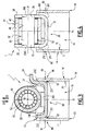
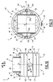
- the mechanical system 1 represented on figures 1 to 7 is of the cam follower type, adapted to equip an injection pump for a motor vehicle, preferably for a gasoline engine car, not shown.
- the system 1 comprises a tappet 10, an insert 20, a pin 30, a roller 40 and a bearing 50.
- Pin 30, roller 40 and bearing 50 are centered on a transverse axis X1, while tappet 10 is centered on a longitudinal axis Y1.
- Axis X1 and Y1 are perpendicular.
- the bearing 50 consists of needles 52. Alternatively, it may consist of cylindrical rollers or a sliding bushing.
- Tappet 10 comprises a cylindrical tappet body 11 centered on axis Y1 and extending between an upper edge 12 and a lower edge 13.
- a first direction D1 is defined along axis Y1 toward lower edge 13, while a second direction D2 opposed to D1 is defined along axis Y1 toward upper edge 12.
- Body 11 has a cylindrical outer surface 14 and a cylindrical inner surface 15 delimiting a cavity 16 inside tappet 10.
- This cavity 16 is adapted to receive a plunger or push rod, not shown, following tappet 10 along axis Y1.
- This cavity 16 is also adapted to receive insert 20.
- tappet 10 is devoid of any through hole extending between outer surface 14 and inner surface 15 of body 11.
- Tappet 10 is movable back and forth along axis Y1, alternatively in direction D1 or D2, with surface 14 sliding in a non-represented bore belonging to the injection pump or motor. Tappet 10 allows roller 40 to move along direction D2 up to contact with the non-represented cam.
- Tappet 10 can be made of synthetic material, by example polyamide 6,6 (PA) or polyether-ether-ketone (PEEK), or made of metal, by example steel. Material of the tappet 10 is chosen resistant to oil flow and its additives, and temperature variations.
- Insert 20 comprises a central core 21 and four lateral tab 22, 23, 25 and 26 extending from central portion 21 opposite axis Y1, then partly along a direction parallel to axis Y1.
- Each tab 22, 23, 25 and 26 comprises a curved portion, respectively 221, 231, 251 and 261, extending from core 21 opposite axis Y1 then curved from radial direction to upper direction; and an axial portion, respectively 222, 232, 252 and 262, extending along a direction parallel to axis Y1.
- Portions 222 and 223 are curved around axis Y1 and adapted to rest against bore 15 of tappet 10.
- Portion 252 is a lateral flange comprising a curved upper surface 253, two plane lower surfaces 254 and a cylindrical bore 258.
- Portion 262 is a lateral flange comprising a curved upper surface 263, two plane lower surfaces 264 and a cylindrical bore 268. Bores 258 and 268 are preferably machined.
- Insert 20 forms a support element for pin 30, roller 40 and bearing 50.
- bores 258 and 268 of insert 20 are adapted to receive pin 30, on which roller 40 and bearing 50 are mounted.
- the two lateral flanges 252 and 262 extend parallel to axis Y1 in a bifurcated manner, on both side of axis Y1, with surfaces 254 and 264 resting against edge 12.
- the flanges 252 and 262 delimit between them an intermediate gap 27.
- Both bores 258 and 268 extend through flanges 252 and 262 along same axis X1 and have the same diameter.
- Bores 258 and 268 form support portions adapted to receive ends 35 and 36 of pin 30. In other words, each end 35 and 36 is supported by one of the two bores 258 and 268.
- pin 30 is supported by the insert 20, particularly along directions D1 and D2 parallel to axis Y1.
- insert 20 comprises an antirotation device 24 integrally formed thereto.
- Device 24 is a pin protruding from tab 23 along a direction parallel to an axis Z1 perpendicular to axes X1 and Y1.
- Pin 24 has a curved portion 241 and a radial portion 242.
- Portion 241 extends from tab 23 along axis Y1 then is curved opposite axis Y1 along axis Z1.
- Portion 242 extends along axis Z1, opposite axis Y1.
- Portion 242 comprises two lateral faces 243 and upper and lower faces 244.
- pin 24 and more precisely faces 243 cooperates with a non-represented guiding groove, formed in the bore surrounding the tappet.
- pin 24 prevents tappet 10 from rotating in this bore around axis Y1.
- lower and upper faces 244 of pin 24 may form end stops adapted to abut against extremities of the guiding groove or of another part.
- Insert 20 is preferably made of metal, by example steel such as XC75. Material of insert 20 is chosen resistant to oil flow, temperature variations and mechanical strains. Insert 20 is preferably formed by stamping. In other words, elements 21 to 26 are delimited in a plane metal sheet, and then formed by stamping. Holes 28 are delimited between portions 221, 231, 251 and 261, in order to save material and avoid cracks when insert 20 is deformed by stamping. Insert 20 is clamped inside body 11, preferably force-fitted. Alternatively, insert 20 is mounted inside body 11 with a play radially to axis Y1, and then fixed to body 11, for instance by crimping, welding or soldering.
- Body 11 comprises local deformations 90 and 100 for fixing insert 20 to tappet 10. Deformations 100 are made after deformations 90. On the example of figures 1 to 7 , body 11 includes four deformations 90 regularly distributed around axis Y1 and five deformations 100 distributed on edge 12. Deformations 90 may be made by punching outer surface 14 of body 11, thus including a recess 91 formed on outer surface 14 and a protrusion 92 formed on inner surface 15 toward axis Y1. Portions 221 and 231 of insert 20 come in bearing contact with protrusions 92 inside cavity 16, thus preventing insert 20 to move inside cavity 16 along direction D1, as shown on figure 3 . In other words, body 11 supports insert 20 along direction D1.
- body 11 may comprise only two deformations 90, with protrusions 92 in contact with portions 221 and 231 of insert 60.
- Deformations 90 can be made before or after mounting insert 20 inside body 11.
- Deformations 100 are made by punching material of edge 12 against insert 20 along direction D1, thus preventing insert 20 to move along direction D2 and outside cavity 16 at edge 12. Thanks to deformations 90 and 100, insert 20 is crimped to body 11.
- Pin 30 comprises a cylindrical surface 32 extending between two pin ends 35 and 36.
- pin ends 35 and 36 are adapted to be caulked, respectively in bores 258 and 268.
- Pin 30 is made of metal, such as steel or bronze. If made of steel, pin 30 is preferably subjected to heat treatment before the caulking step. More precisely, pin ends 35 and 36 may be subjected to an induction hardening step just before the caulking step.
- Roller 40 has an outer cylindrical surface 41 and an inner cylindrical bore 42 centered on axis X1.
- Surface 41 is intended to bear against an outer surface of a non-represented cam, synchronized with the internal combustion engine camshaft.
- Surface 41 is preferably subjected to heat treatment to increase its resistance to load and/or wear.
- Needle bearing 50 comprises a series of needles 52 extending parallel to axis X1 and distributed regularly around axis X1. Needles 52 are interposed between surface 32 of pin 30 and surface 42 of roller 40.
- roller 40 and rolling bearing 50 are positioned before pin 30 in the intermediate gap 27 between the two flanges 252 and 262. Then pin 30 is inserted inside bores 258 and 268 of insert 20 and inside rolling bearing 50. Finally pin ends 35 and 36 are caulked by press-fit in bores 258 and 268. At this stage, roller 40 is movable in rotation relative to pin 30 around axis X1. Pin axis, roller axis and rolling bearing axis merge with axis X1. Roller 40 is then adapted to roll, more precisely its surface 41 can roll, on an outer surface of the non-represented cam.
- the load applied on surface 41 of roller 40 is transmitted to rolling bearing 50, then to pin 30, then to insert 20, then to tappet 10 and to the non-represented plunger or push rod located inside cavity 16 of tappet 10. Core 21 of insert 20 rests in contact against this plunger or push rod. Thanks to the invention, most of the load applied on roller 40 along direction D1 is received by insert 20 instead of tappet 10, then is transmitted to the plunger or push rod. Tappet 10 slides back and forth but bears few mechanical strains along axis Y1.
- insert 20 has three different functions. Insert 20 forms a support element for pin 30. Insert 20 comprises an antirotation device 24 integrally formed thereto. Insert 20 is in resting contact with the plunger or push rod located inside cavity 16 for load transmission along direction D1.
- a second embodiment of the invention is represented on figure 8 .
- No local deformations 90 are made near portions 251 and 261 of insert 20, while portions 221 and 231 of insert 20 come in bearing contact with protrusions 92 inside cavity 16, thus preventing insert 20 to move inside cavity 16 along direction D1.
- a third embodiment of the invention is represented on figure 9 .
- Portions 221, 231, 251 and 261 of insert 20 come in bearing contact with protrusions 92 inside cavity 16, thus preventing insert 20 to move inside cavity 16 along direction D1.
- System 1 comprises an insert 320, with constitutive portions having references increased by 300 in comparison with the first embodiment.
- Tappet 10 comprises a central radial portion 17 extending from body 11 toward axis Y1, between edges 12 and 13.
- Tappet 10 includes a lower cavity 16 and an upper cavity 18 delimited either side of portion 17.
- Cavity 16 is adapted to receive a shaft, not shown, for moving tappet 10 along axis Y1.
- Cavity 18 is adapted to partly receive pin 30, roller 40 and bearing 50.
- Portion 17 comprises plane surfaces 17a for receiving planes surfaces 321 a of insert 320 in bearing contact along directions parallel to axis Z1.
- Four holes 19 extend through portion 17 parallel to axis Y1, connecting cavities 16 and 18, to allow a flow of lubricant therebetween.
- Tappet 10 also comprises an antirotation device 80 integrally formed thereto, on its outer surface 14.
- Device 80 is a pin protruding from surface 14 along a direction parallel to an axis Z1 perpendicular to axes X1 and Y1.
- Pin 80 has an outer surface 82 having a rounded shape in a sectional plane perpendicular to axis Y1, as shown on figure 11 .
- Surface 82 cooperates with a non-represented guiding groove, formed in the bore surrounding the tappet.
- pin 80 prevents tappet 10 from rotating in this bore around axis Y1.
- Pin 80 extends along axis Y1 between two extremities 84 and 86, each having a rounded shape in a sectional plane comprising axis Y1 and Z1.
- extremities 84 and 86 may form end stops adapted to abut against extremities of the guiding groove or of another part.
- pin 80 is located substantially at half length of surface 14 along axis Y1, between edges 12 and 13.
- pin 80 is moulded as one single part together with tappet 10.
- pin 80 may be formed by plastic deformation of tappet 10, for example by punching from inside cavity 16 of tappet 10, with a punch applied to bore 15 and deforming body 11.
- pin 80 may be machined in the mass of tappet 10.
- Tappet 10 also includes two annular grooves 171 and 172 centered on axis Y1. Grooves 171 and 172 are open at surface 14. Groove 171 is closer to edge 13, while groove 172 is closer to edge 12. Tappet 10 also includes two annular inserts 181 and 182, preferably made of metal. Insert 181 is fitted inside groove 171, while insert 182 is fitted inside groove 172. Inserts 181 and 182 allows reducing wear of tappet 10 sliding in the non-represented bore.
- Tappet 10 also comprises a bearing portion 120 located at its upper edge 12, extending from upper edge 12 of body 11 opposite lower edge 13.
- Bearing portion 120 is adapted to receive pin 30, on which roller 40 and bearing 50 are mounted.
- bearing portion 120 comprises two pairs of stops or tabs 121 and 122 extending from portion 120 in a bifurcated manner, on both side of axis Y1.
- Each of the tabs 121 and 122 is elastically deformable. Pair of tabs 121 is projected substantially in a first plane parallel to axis Y1, while pair of tabs 122 is projected substantially in a second plane parallel to axis Y1.
- the pairs of tabs 121 and 122 delimit between them an intermediate gap 127 joining cavity 18.
- each pair of tabs 121 and 122 delimits a partial cylindrical bore, respectively 123 and 124. Partial bores 123 and 124 are centered on axis X1 and have the same diameter.
- the pairs of tabs 121 and 122 provide radial retention of pin 30 radially to axis X1, particularly along a direction parallel to axis Z1.
- bearing portion 120 of tappet 10 is also provided with two opposed ribs 125 and 126 for axial retention of pin 30 along axis X1.
- Ribs 125 and 126 extend from edge 12 parallel to axis Y1 and perpendicular to axis X1.
- Rib 125 is located between tabs 121, while rib 126 is located between tabs 122, on respective side of axis Y1.
- Each of the ribs 125 and 126 is elastically deformable. Together with the pairs of tabs 121 and 122, the ribs 125 and 126 delimit the intermediate gap 127 receiving pin 30.
- the ribs 125 and 126 have inner faces, respectively 125a and 126a, resting on either side of the pin 30 along the first axis X1.
- the ribs 125 and 126 provide axial retention of pin 30 relative to axis X1.
- bearing portion 120 may have different configurations without leaving the scope of the invention.
- Tabs 121 and 122 and ribs 125 and 126 are designed with a mechanical resistance sufficient when system 1 is in service.
- tabs 121 and 122 and ribs 125 and 126 are integrally formed with tappet 10.
- insert 320 has a U-shape in a plane including axes X1 and Y1.
- Insert 320 comprises a plane central portion or core 321 and two plane lateral portions 552 and 562.
- Insert 60 comprises a curved portion 551 connecting portions 321 and 552 and a curved portion 561 connecting portions 321 and 562.
- Central portion 321 comprises lateral plane surfaces 321 a in contact with plane surfaces 17a of central portion 17.
- Curved portions 551 and 561 are in contact with protrusions 92 formed on body 11.
- body 11 supports insert 320 along direction D1.
- Portion 552 comprises a half-cylindrical section 558 supporting end 35 of pin 30 together with bore 123.
- Portion 562 comprises a half-cylindrical section 568 supporting end 36 of pin 30 together with bore 124. Sections 558 and 568 are preferably machined.
- roller 40 and rolling bearing 50 are inserted in the intermediate gap 127.
- Pin ends 35 and 36 are clipped into the pairs of tabs 121 and 122, in contact with bores 123 and 124, ribs 125 and 126 and support sections 558 and 568.
- roller 40 is movable in rotation relative to pin 30 around axis X1.
- Pin axis, roller axis and rolling bearing axis merge with axis X1.
- Roller 40 is then adapted to roll, more precisely its surface 41 can roll, on an outer surface of the non-represented cam.
- the load applied on surface 41 of roller 40 is transmitted to rolling bearing 50, then to pin 30, then to insert 320 and to bearing portion 120 of tappet 10, then to the non-represented plunger or push rod located inside cavity 16 of tappet 10.
- Core 321 of insert 320 rests in contact against this plunger or push rod.
- Insert 320 is more resistant than bearing portion 120 to load transmitted from roller 40, in other words insert 320 increases mechanical resistance of system 1.Tappet 10 slides back and forth along direction D1 and D2 but bears few mechanical strains along axis Y1.
- tappet 10, insert 20 or 320 and/or roller element 40 may have different configurations, by example depending on the intended application of system 1.
- system 1 may constitute a rocker arm, wherein the support element 10 is not a tappet and wherein the roller element 40 is secured to an arm and a tappet, for example acting on a valve stem.
- system 1 comprises no rolling bearing 50, while pin 30 and roller 40 form together a plain bearing.
- bearing 50 may be replaced by a bushing.
- system 1 comprises at least two antirotation devices 24 and/or 80.
- two antirotation devices 24 may be formed on tab 23 and be aligned parallel to axis Y1, so that they can be positioned in the same groove formed in bore surrounding tappet 10.
- the two antirotation devices 24 may be diametrically opposed relative to axis Y1, with a first device formed on tab 23 and a second device formed on tab 24.
- two antirotation devices 80 may be formed on body 11, aligned along direction D1 parallel to axis Y1 or diametrically opposed on either sides of body 11 relative to axis Y1.
- number, shape and/or position of device(s) 24 and/or 80 may vary without leaving the scope of the invention.
- bearing portion 120 is devoid of pairs of tabs 121 and 122.
- Pin 30 is positioned in contact with partial bores 123 and 124 formed in bearing portion 120 and with sections 558 and 568 formed in insert 320.
- ribs 125 and 126 each comprises a stub protruding along axis X1 toward the opposite rib 126 or 125.
- a recess is formed by a blind hole inside each end 35 of the pin 30.
- stubs 28 and 29 ensure radial retention of pin 30 relative to axis X1.
- tappet 10 may be devoid of tabs 121 and 122.
- the pairs of tabs 121 and 122 and/or the ribs 125 and 126 are integrally formed with the insert 320 positioned inside body 11.
- grooves 171 and 172 and inserts 181 and 182 are not annular. In other words, they extend only partly around axis Y1.
- groove 171 and insert 181 extend around axis Y1 over an angle of 180 degrees on the same side as rib 125
- groove 172 and insert 182 extend around axis Y1 over an angle of 180 degrees on the same side as rib 126.
- system 1 is such that insert 20 or 320 supports pin 30, while tappet body 11 supports insert 20 or 320, along at least the direction D1 parallel to axis Y1.
- Insert 20 supports pin 30, while tappet body 11 supports insert 20, along both directions D1 and D2.
- Insert 320 supports pin 30, while tappet body 11 supports insert 320, along direction D1 but not direction D2.
- insert 20 or 320 rests directly against protrusions 92 formed in body 11 without an intermediate ring and without specific recesses formed in insert 20 or 320.
Landscapes
- Engineering & Computer Science (AREA)
- General Engineering & Computer Science (AREA)
- Mechanical Engineering (AREA)
- Chemical & Material Sciences (AREA)
- Combustion & Propulsion (AREA)
- Valve-Gear Or Valve Arrangements (AREA)
- Fuel-Injection Apparatus (AREA)
- Gears, Cams (AREA)
Claims (15)
- Mechanisches System (1), umfassend:- einen Stößel (10), der einen Körper (11) aufweist,- einen Einsatz (20; 320), der in dem Körper (11) befestigt ist,- einen Stift (30), der sich entlang einer ersten Achse (X1) erstreckt, und- ein Rollenelement (40), das in Bezug auf den Stift (30) um die erste Achse (X1) drehbar ist, dadurch gekennzeichnet, dassder Einsatz (20; 320) den Stift (30), während der Körper (11) den Einsatz (20; 320) stützt, entlang mindestens einer ersten Richtung (D1), die zu einer zweiten Achse (Y1) parallel ist, die zu der ersten Achse (X1) senkrecht ist, stützt.
- Mechanisches System (1) nach Anspruch 1, wobei der Körper (11) mindestens eine lokale Verformung (90) aufweist, die ausgelegt ist zu verhindern, dass sich der Einsatz (20; 320) entlang der ersten Richtung (D1) bewegt, wenn das mechanische System (1) in Betrieb ist.
- Mechanisches System (1) nach einem der vorhergehenden Ansprüche, wobei der Körper (11) mindestens eine lokale Verformung (100) aufweist, die ausgelegt ist zu verhindern, dass sich der Einsatz (20) entlang einer zweiten Richtung (D2), die der ersten Richtung (D1) entgegengesetzt ist, entlang der zweiten Achse (Y1) bewegt, wenn das mechanische System (1) in Betrieb ist.
- Mechanisches System (1) nach einem der vorhergehenden Ansprüche, wobei der Einsatz (20; 320) zwei Stützabschnitte (258, 268; 558, 568) umfasst und der Stift (30) zwei gegenüberliegende Enden (35, 36) umfasst, die jeweils von einem der zwei Stützabschnitte (258, 268; 558, 568) des Einsatzes (20; 320) entlang mindestens der ersten Richtung (D1) gestützt werden.
- Mechanisches System (1) nach einem der vorhergehenden Ansprüche, wobei der Körper (11) eine zylindrische Form aufweist, die auf der zweiten Achse (Y1) zentriert ist, wobei der Stößel (10) vorzugsweise kein Durchgangsloch aufweist, das sich zwischen einer äußeren Oberfläche (14) und einer inneren Oberfläche (15) des Körpers (11) erstreckt.
- Mechanisches System (1) nach einem der vorhergehenden Ansprüche, umfassend zwei Rippen (125, 126), die auf jeder Seite der Enden (35, 36) des Stiftes (30) zur axialen Zurückhaltung des Stiftes (30) entlang der ersten Achse (X1) aufliegen.
- Mechanisches System (1) nach einem der vorhergehenden Ansprüche 1 bis 6, wobei der Einsatz (20; 320) in dem Körper (11) eingespannt, vorzugsweise in dem Körper (11) eingepresst ist.
- Mechanisches System (1) nach einem der vorhergehenden Ansprüche 1 bis 6, wobei der Einsatz (20; 320) mit einem Spiel in dem Körper (11) befestigt ist, dann an dem Körper (11) beispielsweise durch Crimpen, Schweißen oder Löten befestigt ist.
- Mechanisches System (1) nach einem der vorhergehenden Ansprüche, wobei der Körper (11) aus synthetischem Material, beispielsweise Polyamid oder Polyetherketon hergestellt ist oder aus einem Metall, beispielsweise Stahl hergestellt ist.
- Mechanisches System (1) nach einem der vorhergehenden Ansprüche, umfassend mindestens eine Drehschutzvorrichtung (24; 80), die mit dem Körper (11) oder mit dem Einsatz (20; 320) einstückig ausgebildet ist.
- Mechanisches System (1) nach einem der vorhergehenden Ansprüche, umfassend ein Lager (50), das zwischen dem Stift (30) und dem Rollenelement (40) angeordnet ist.
- Mechanisches System (1) nach einem der vorhergehenden Ansprüche, wobei es einen Nockenstößel bildet, wobei der Stößel (10) entlang der zweiten Achse (Y1) beweglich ist und wobei das Rollenelement (40) ausgelegt ist, auf einer äußeren Oberfläche eines Nockens zu rollen.
- Einspritzpumpe für ein Kraftfahrzeug, wobei sie ein mechanisches System (1) nach einem der Ansprüche 1 bis 12 umfasst.
- Ventilaktor für ein Kraftfahrzeug, wobei er ein mechanisches System (1) nach einem der Ansprüche 1 bis 12 umfasst.
- Verfahren zum Herstellen eines mechanischen Systems (1) nach einem der Ansprüche 1 bis 12, wobei der Stift (30) in dem Einsatz (20; 320) angeordnet wird, während der Einsatz (20; 320) in dem Körper (11) angeordnet wird, der vorzugsweise mindestens eine lokale Verformung (90) aufweist, die ausgelegt ist zu verhindern, dass sich der Einsatz (20; 320) entlang der ersten Richtung (D1) bewegt, wenn das mechanische System (1) in Betrieb ist.
Priority Applications (5)
| Application Number | Priority Date | Filing Date | Title |
|---|---|---|---|
| EP13186511.5A EP2853738B1 (de) | 2013-09-27 | 2013-09-27 | Mechanisches System, Einspritzpumpe und Ventilaktor mit einem solchen mechanischen System und Herstellungsverfahren |
| JP2014196258A JP2015068503A (ja) | 2013-09-27 | 2014-09-26 | 機械システム、そうした機械システムを備える射出ポンプならびにバルブアクチュエータ、およびその製造方法 |
| CN201410510458.1A CN104514656B (zh) | 2013-09-27 | 2014-09-28 | 机械系统,包括它的喷射泵和阀致动器以及制造方法 |
| US14/499,645 US9695924B2 (en) | 2013-09-27 | 2014-09-29 | Mechanical system, injection pump and valve actuator comprising such a mechanical system and manufacturing method |
| US14/499,989 US9551408B2 (en) | 2013-09-27 | 2014-09-29 | Mechanical system, injection pump and valve actuator comprising such a mechanical system and manufacturing method |
Applications Claiming Priority (1)
| Application Number | Priority Date | Filing Date | Title |
|---|---|---|---|
| EP13186511.5A EP2853738B1 (de) | 2013-09-27 | 2013-09-27 | Mechanisches System, Einspritzpumpe und Ventilaktor mit einem solchen mechanischen System und Herstellungsverfahren |
Publications (2)
| Publication Number | Publication Date |
|---|---|
| EP2853738A1 EP2853738A1 (de) | 2015-04-01 |
| EP2853738B1 true EP2853738B1 (de) | 2016-04-27 |
Family
ID=49274469
Family Applications (1)
| Application Number | Title | Priority Date | Filing Date |
|---|---|---|---|
| EP13186511.5A Active EP2853738B1 (de) | 2013-09-27 | 2013-09-27 | Mechanisches System, Einspritzpumpe und Ventilaktor mit einem solchen mechanischen System und Herstellungsverfahren |
Country Status (4)
| Country | Link |
|---|---|
| US (2) | US9695924B2 (de) |
| EP (1) | EP2853738B1 (de) |
| JP (1) | JP2015068503A (de) |
| CN (1) | CN104514656B (de) |
Families Citing this family (25)
| Publication number | Priority date | Publication date | Assignee | Title |
|---|---|---|---|---|
| DE102014223597B4 (de) * | 2014-10-08 | 2019-02-07 | Continental Automotive Gmbh | Rolle für einen Rollenstößel einer Kraftstoffhochdruckpumpe, Rollenstößel, Kraftstoffhochdruckpumpe und Brennkraftmaschine |
| EP3026255B1 (de) * | 2014-11-27 | 2020-11-18 | Aktiebolaget SKF | Mechanisches System zur Formung eines Kurvenrollers oder eines Kipphebels, Einspritzpumpe oder Ventilstellglied mit solch einem mechanischen System und Verfahren zur Herstellung solch eines mechanischen Systems |
| EP3085945B1 (de) * | 2015-04-23 | 2019-03-27 | Aktiebolaget SKF | Nockenfolger, einspritzpumpe und ventilaktuator mit solch einem nockenfolger und herstellungsverfahren |
| US10024286B2 (en) * | 2015-07-15 | 2018-07-17 | GT Technologies | Tappet assembly for use in an internal combustion engine high-pressure fuel system |
| EP3121436B1 (de) | 2015-07-21 | 2018-05-02 | Aktiebolaget SKF | Nockenfolgerrollenvorrichtung und zugehöriges herstellungsverfahren |
| GB2542349A (en) * | 2015-09-15 | 2017-03-22 | Gm Global Tech Operations Llc | Fuel unit pump and internal combustion engine comprising it |
| EP3165722B1 (de) | 2015-11-05 | 2019-04-17 | Aktiebolaget SKF | Rollenstössel mit einsatz |
| EP3173591B1 (de) | 2015-11-24 | 2018-07-11 | Aktiebolaget SKF | Nockenfolgerrollenvorrichtung mit abstandsstück |
| EP3173590B1 (de) | 2015-11-24 | 2018-06-20 | Aktiebolaget SKF | Nockenfolgerrollenvorrichtung mit unterlegscheibe |
| EP3173592B1 (de) | 2015-11-24 | 2021-01-06 | Aktiebolaget SKF | Nockenfolgerrollervorrichtung mit schmiermittelzuführungslöchern und schmierverfahren |
| EP3173612B1 (de) | 2015-11-24 | 2019-09-18 | Aktiebolaget SKF | Nockenfolgerrollenvorrichtung mit haltestopfen |
| EP3176393B1 (de) | 2015-12-03 | 2018-06-13 | Aktiebolaget SKF | Nockenfolgerrollenvorrichtung mit abstandshalter und erhöhter verschleissfestigkeit |
| US10119607B2 (en) * | 2016-04-15 | 2018-11-06 | Koyo Bearings North America Llc | Follower mechanism |
| US9863382B2 (en) * | 2016-05-25 | 2018-01-09 | Hangzhou Xzb Tech Co., Ltd | High pressure oil pump roller tappet |
| CN106050504B (zh) * | 2016-07-12 | 2018-08-14 | 杭州新坐标科技股份有限公司 | 一种发动机用高压油泵滚子挺柱 |
| DE102017218018A1 (de) | 2016-10-28 | 2018-05-03 | Aktiebolaget Skf | Nockenfolgerollenvorrichtung |
| US10247052B2 (en) * | 2017-07-31 | 2019-04-02 | Caterpillar Inc. | Guide assembly for valve lifters of engines |
| US10697413B2 (en) * | 2018-06-04 | 2020-06-30 | GT Technologies | Tappet assembly for use in a high-pressure fuel system of an internal combustion engine |
| US11111893B2 (en) * | 2018-06-04 | 2021-09-07 | GT Technologies | Tappet assembly for use in a high-pressure fuel system of an internal combustion engine |
| WO2019236575A2 (en) * | 2018-06-04 | 2019-12-12 | GT Technologies | Tappet assembly for use in a high-pressure fuel system of an internal combustion engine |
| CN109372671A (zh) * | 2018-12-18 | 2019-02-22 | 杭州新坐标科技股份有限公司 | 高压泵滚子挺柱 |
| US10941737B2 (en) * | 2019-01-14 | 2021-03-09 | Koyo Bearings North America Llc | Follower mechanism with anti-rotation feature |
| US11143059B2 (en) | 2019-10-03 | 2021-10-12 | Koyo Bearings North America Llc | Tappet assembly with unground outer cup |
| US11149593B2 (en) | 2019-10-03 | 2021-10-19 | Koyo Bearings North America Llc | Tappet assembly with formed anti-rotation alignment device |
| JP7430104B2 (ja) * | 2020-04-22 | 2024-02-09 | 株式会社オティックス | ローラリフタ |
Family Cites Families (11)
| Publication number | Priority date | Publication date | Assignee | Title |
|---|---|---|---|---|
| DE3247026A1 (de) * | 1982-12-18 | 1984-06-20 | Klöckner-Humboldt-Deutz AG, 5000 Köln | Elastischer rollenstoessel |
| DE4227853C2 (de) * | 1992-08-22 | 1996-05-30 | Bosch Gmbh Robert | Kraftstoffeinspritzpumpe für Brennkraftmaschinen |
| US5307769A (en) | 1993-06-07 | 1994-05-03 | General Motors Corporation | Low mass roller valve lifter assembly |
| US5553512A (en) * | 1993-09-14 | 1996-09-10 | Ntn Corporation | Roller tappet having yoke member with flat top plate |
| JP2002332809A (ja) | 2001-05-07 | 2002-11-22 | Fuji Oozx Inc | 内燃機関における動弁機構 |
| CN100410526C (zh) * | 2004-01-14 | 2008-08-13 | 博世株式会社 | 燃料供给泵及挺杆结构体 |
| US7793583B2 (en) | 2006-12-06 | 2010-09-14 | Schaeffler Kg | Mechanical tappet in particular for a fuel pump of an internal combustion engine |
| JP4930478B2 (ja) * | 2008-09-04 | 2012-05-16 | トヨタ自動車株式会社 | ローラリフタ、ローラリフタの製造方法、および液体用ポンプ |
| EP2607636B1 (de) * | 2011-12-23 | 2015-10-14 | Aktiebolaget SKF | Mechanisches System, Einspritzpumpe mit solch einem mechanischen System und Verfahren zur Herstellung solch eines mechanischen Systems |
| JP5992540B2 (ja) * | 2012-02-08 | 2016-09-14 | コーヨー ベアリングス ノース アメリカ エルエルシー | フォロワー機構 |
| JP6110080B2 (ja) * | 2012-06-20 | 2017-04-05 | 株式会社オティックス | 内燃機関用のローラリフタ |
-
2013
- 2013-09-27 EP EP13186511.5A patent/EP2853738B1/de active Active
-
2014
- 2014-09-26 JP JP2014196258A patent/JP2015068503A/ja active Pending
- 2014-09-28 CN CN201410510458.1A patent/CN104514656B/zh active Active
- 2014-09-29 US US14/499,645 patent/US9695924B2/en not_active Expired - Fee Related
- 2014-09-29 US US14/499,989 patent/US9551408B2/en active Active
Also Published As
| Publication number | Publication date |
|---|---|
| US20150090209A1 (en) | 2015-04-02 |
| CN104514656B (zh) | 2019-10-11 |
| JP2015068503A (ja) | 2015-04-13 |
| US9695924B2 (en) | 2017-07-04 |
| EP2853738A1 (de) | 2015-04-01 |
| US20150090205A1 (en) | 2015-04-02 |
| US9551408B2 (en) | 2017-01-24 |
| CN104514656A (zh) | 2015-04-15 |
Similar Documents
| Publication | Publication Date | Title |
|---|---|---|
| US9551408B2 (en) | Mechanical system, injection pump and valve actuator comprising such a mechanical system and manufacturing method | |
| EP2853698B1 (de) | Ventilstössel, Einspritzpumpe und Ventilaktor mit einem solchen Ventilstössel und Herstellungsverfahren | |
| EP2853696B1 (de) | Mechanisches System, Einspritzpumpe und Ventilaktor mit einem solchen mechanischen System und Herstellungsverfahren | |
| EP3026232B1 (de) | Mechanisches System zur Formung eines Kurvenrollers oder eines Kipphebels, Einspritzpumpe oder Ventilstellglied mit solch einem mechanischen System und Verfahren zur Herstellung solch eines mechanischen Systems | |
| US10006425B2 (en) | Cam follower, injection pump and valve actuator having such a cam follower, and manufacturing method | |
| EP2853699B1 (de) | Stössel, Einspritzpumpe und Ventilaktor mit einem solchen Stössel und Herstellungsverfahren eines solchen Stössel | |
| EP3026231B1 (de) | Mechanisches System zur Formung eines Kurvenrollers oder eines Kipphebels, Einspritzpumpe oder Ventilstellglied mit solch einem mechanischen System und Verfahren zur Herstellung solch eines mechanischen Systems | |
| US9933062B2 (en) | Mechanical system forming a cam follower or a rocker arm | |
| US9752670B2 (en) | Mechanical system forming a cam follower or a rocker arm | |
| US9745934B2 (en) | Mechanical system forming a cam follower or a rocker arm | |
| EP2853697B1 (de) | Mechanisches System, Einspritzpumpe und Ventilaktor mit einem solchen mechanischen System und Herstellungsverfahren | |
| US10385956B2 (en) | Mechanical system forming a cam follower or a rocker arm |
Legal Events
| Date | Code | Title | Description |
|---|---|---|---|
| PUAI | Public reference made under article 153(3) epc to a published international application that has entered the european phase |
Free format text: ORIGINAL CODE: 0009012 |
|
| 17P | Request for examination filed |
Effective date: 20130927 |
|
| AK | Designated contracting states |
Kind code of ref document: A1 Designated state(s): AL AT BE BG CH CY CZ DE DK EE ES FI FR GB GR HR HU IE IS IT LI LT LU LV MC MK MT NL NO PL PT RO RS SE SI SK SM TR |
|
| AX | Request for extension of the european patent |
Extension state: BA ME |
|
| R17P | Request for examination filed (corrected) |
Effective date: 20150918 |
|
| RBV | Designated contracting states (corrected) |
Designated state(s): AL AT BE BG CH CY CZ DE DK EE ES FI FR GB GR HR HU IE IS IT LI LT LU LV MC MK MT NL NO PL PT RO RS SE SI SK SM TR |
|
| GRAP | Despatch of communication of intention to grant a patent |
Free format text: ORIGINAL CODE: EPIDOSNIGR1 |
|
| RIC1 | Information provided on ipc code assigned before grant |
Ipc: F02M 59/10 20060101ALI20151009BHEP Ipc: F01L 1/04 20060101ALI20151009BHEP Ipc: F16H 53/06 20060101ALI20151009BHEP Ipc: F04B 1/04 20060101AFI20151009BHEP Ipc: F01L 1/14 20060101ALI20151009BHEP |
|
| INTG | Intention to grant announced |
Effective date: 20151106 |
|
| GRAS | Grant fee paid |
Free format text: ORIGINAL CODE: EPIDOSNIGR3 |
|
| GRAA | (expected) grant |
Free format text: ORIGINAL CODE: 0009210 |
|
| AK | Designated contracting states |
Kind code of ref document: B1 Designated state(s): AL AT BE BG CH CY CZ DE DK EE ES FI FR GB GR HR HU IE IS IT LI LT LU LV MC MK MT NL NO PL PT RO RS SE SI SK SM TR |
|
| REG | Reference to a national code |
Ref country code: GB Ref legal event code: FG4D |
|
| REG | Reference to a national code |
Ref country code: CH Ref legal event code: EP |
|
| REG | Reference to a national code |
Ref country code: AT Ref legal event code: REF Ref document number: 795117 Country of ref document: AT Kind code of ref document: T Effective date: 20160515 |
|
| REG | Reference to a national code |
Ref country code: IE Ref legal event code: FG4D |
|
| REG | Reference to a national code |
Ref country code: DE Ref legal event code: R096 Ref document number: 602013006922 Country of ref document: DE |
|
| REG | Reference to a national code |
Ref country code: LT Ref legal event code: MG4D |
|
| REG | Reference to a national code |
Ref country code: NL Ref legal event code: MP Effective date: 20160427 |
|
| REG | Reference to a national code |
Ref country code: AT Ref legal event code: MK05 Ref document number: 795117 Country of ref document: AT Kind code of ref document: T Effective date: 20160427 |
|
| REG | Reference to a national code |
Ref country code: FR Ref legal event code: PLFP Year of fee payment: 4 |
|
| PG25 | Lapsed in a contracting state [announced via postgrant information from national office to epo] |
Ref country code: NL Free format text: LAPSE BECAUSE OF FAILURE TO SUBMIT A TRANSLATION OF THE DESCRIPTION OR TO PAY THE FEE WITHIN THE PRESCRIBED TIME-LIMIT Effective date: 20160427 |
|
| PG25 | Lapsed in a contracting state [announced via postgrant information from national office to epo] |
Ref country code: PL Free format text: LAPSE BECAUSE OF FAILURE TO SUBMIT A TRANSLATION OF THE DESCRIPTION OR TO PAY THE FEE WITHIN THE PRESCRIBED TIME-LIMIT Effective date: 20160427 Ref country code: FI Free format text: LAPSE BECAUSE OF FAILURE TO SUBMIT A TRANSLATION OF THE DESCRIPTION OR TO PAY THE FEE WITHIN THE PRESCRIBED TIME-LIMIT Effective date: 20160427 Ref country code: LT Free format text: LAPSE BECAUSE OF FAILURE TO SUBMIT A TRANSLATION OF THE DESCRIPTION OR TO PAY THE FEE WITHIN THE PRESCRIBED TIME-LIMIT Effective date: 20160427 Ref country code: NO Free format text: LAPSE BECAUSE OF FAILURE TO SUBMIT A TRANSLATION OF THE DESCRIPTION OR TO PAY THE FEE WITHIN THE PRESCRIBED TIME-LIMIT Effective date: 20160727 |
|
| PG25 | Lapsed in a contracting state [announced via postgrant information from national office to epo] |
Ref country code: ES Free format text: LAPSE BECAUSE OF FAILURE TO SUBMIT A TRANSLATION OF THE DESCRIPTION OR TO PAY THE FEE WITHIN THE PRESCRIBED TIME-LIMIT Effective date: 20160427 Ref country code: SE Free format text: LAPSE BECAUSE OF FAILURE TO SUBMIT A TRANSLATION OF THE DESCRIPTION OR TO PAY THE FEE WITHIN THE PRESCRIBED TIME-LIMIT Effective date: 20160427 Ref country code: GR Free format text: LAPSE BECAUSE OF FAILURE TO SUBMIT A TRANSLATION OF THE DESCRIPTION OR TO PAY THE FEE WITHIN THE PRESCRIBED TIME-LIMIT Effective date: 20160728 Ref country code: RS Free format text: LAPSE BECAUSE OF FAILURE TO SUBMIT A TRANSLATION OF THE DESCRIPTION OR TO PAY THE FEE WITHIN THE PRESCRIBED TIME-LIMIT Effective date: 20160427 Ref country code: LV Free format text: LAPSE BECAUSE OF FAILURE TO SUBMIT A TRANSLATION OF THE DESCRIPTION OR TO PAY THE FEE WITHIN THE PRESCRIBED TIME-LIMIT Effective date: 20160427 Ref country code: PT Free format text: LAPSE BECAUSE OF FAILURE TO SUBMIT A TRANSLATION OF THE DESCRIPTION OR TO PAY THE FEE WITHIN THE PRESCRIBED TIME-LIMIT Effective date: 20160829 Ref country code: AT Free format text: LAPSE BECAUSE OF FAILURE TO SUBMIT A TRANSLATION OF THE DESCRIPTION OR TO PAY THE FEE WITHIN THE PRESCRIBED TIME-LIMIT Effective date: 20160427 Ref country code: HR Free format text: LAPSE BECAUSE OF FAILURE TO SUBMIT A TRANSLATION OF THE DESCRIPTION OR TO PAY THE FEE WITHIN THE PRESCRIBED TIME-LIMIT Effective date: 20160427 |
|
| PG25 | Lapsed in a contracting state [announced via postgrant information from national office to epo] |
Ref country code: IT Free format text: LAPSE BECAUSE OF FAILURE TO SUBMIT A TRANSLATION OF THE DESCRIPTION OR TO PAY THE FEE WITHIN THE PRESCRIBED TIME-LIMIT Effective date: 20160427 Ref country code: BE Free format text: LAPSE BECAUSE OF FAILURE TO SUBMIT A TRANSLATION OF THE DESCRIPTION OR TO PAY THE FEE WITHIN THE PRESCRIBED TIME-LIMIT Effective date: 20160427 |
|
| REG | Reference to a national code |
Ref country code: DE Ref legal event code: R097 Ref document number: 602013006922 Country of ref document: DE |
|
| PG25 | Lapsed in a contracting state [announced via postgrant information from national office to epo] |
Ref country code: SK Free format text: LAPSE BECAUSE OF FAILURE TO SUBMIT A TRANSLATION OF THE DESCRIPTION OR TO PAY THE FEE WITHIN THE PRESCRIBED TIME-LIMIT Effective date: 20160427 Ref country code: DK Free format text: LAPSE BECAUSE OF FAILURE TO SUBMIT A TRANSLATION OF THE DESCRIPTION OR TO PAY THE FEE WITHIN THE PRESCRIBED TIME-LIMIT Effective date: 20160427 Ref country code: RO Free format text: LAPSE BECAUSE OF FAILURE TO SUBMIT A TRANSLATION OF THE DESCRIPTION OR TO PAY THE FEE WITHIN THE PRESCRIBED TIME-LIMIT Effective date: 20160427 Ref country code: CZ Free format text: LAPSE BECAUSE OF FAILURE TO SUBMIT A TRANSLATION OF THE DESCRIPTION OR TO PAY THE FEE WITHIN THE PRESCRIBED TIME-LIMIT Effective date: 20160427 Ref country code: EE Free format text: LAPSE BECAUSE OF FAILURE TO SUBMIT A TRANSLATION OF THE DESCRIPTION OR TO PAY THE FEE WITHIN THE PRESCRIBED TIME-LIMIT Effective date: 20160427 |
|
| PG25 | Lapsed in a contracting state [announced via postgrant information from national office to epo] |
Ref country code: SM Free format text: LAPSE BECAUSE OF FAILURE TO SUBMIT A TRANSLATION OF THE DESCRIPTION OR TO PAY THE FEE WITHIN THE PRESCRIBED TIME-LIMIT Effective date: 20160427 |
|
| PLBE | No opposition filed within time limit |
Free format text: ORIGINAL CODE: 0009261 |
|
| STAA | Information on the status of an ep patent application or granted ep patent |
Free format text: STATUS: NO OPPOSITION FILED WITHIN TIME LIMIT |
|
| 26N | No opposition filed |
Effective date: 20170130 |
|
| PG25 | Lapsed in a contracting state [announced via postgrant information from national office to epo] |
Ref country code: MC Free format text: LAPSE BECAUSE OF FAILURE TO SUBMIT A TRANSLATION OF THE DESCRIPTION OR TO PAY THE FEE WITHIN THE PRESCRIBED TIME-LIMIT Effective date: 20160427 |
|
| REG | Reference to a national code |
Ref country code: CH Ref legal event code: PL |
|
| PG25 | Lapsed in a contracting state [announced via postgrant information from national office to epo] |
Ref country code: SI Free format text: LAPSE BECAUSE OF FAILURE TO SUBMIT A TRANSLATION OF THE DESCRIPTION OR TO PAY THE FEE WITHIN THE PRESCRIBED TIME-LIMIT Effective date: 20160427 |
|
| REG | Reference to a national code |
Ref country code: IE Ref legal event code: MM4A |
|
| PG25 | Lapsed in a contracting state [announced via postgrant information from national office to epo] |
Ref country code: LI Free format text: LAPSE BECAUSE OF NON-PAYMENT OF DUE FEES Effective date: 20160930 Ref country code: CH Free format text: LAPSE BECAUSE OF NON-PAYMENT OF DUE FEES Effective date: 20160930 Ref country code: IE Free format text: LAPSE BECAUSE OF NON-PAYMENT OF DUE FEES Effective date: 20160927 |
|
| PG25 | Lapsed in a contracting state [announced via postgrant information from national office to epo] |
Ref country code: LU Free format text: LAPSE BECAUSE OF NON-PAYMENT OF DUE FEES Effective date: 20160927 |
|
| REG | Reference to a national code |
Ref country code: FR Ref legal event code: PLFP Year of fee payment: 5 |
|
| GBPC | Gb: european patent ceased through non-payment of renewal fee |
Effective date: 20170927 |
|
| PG25 | Lapsed in a contracting state [announced via postgrant information from national office to epo] |
Ref country code: HU Free format text: LAPSE BECAUSE OF FAILURE TO SUBMIT A TRANSLATION OF THE DESCRIPTION OR TO PAY THE FEE WITHIN THE PRESCRIBED TIME-LIMIT; INVALID AB INITIO Effective date: 20130927 |
|
| PG25 | Lapsed in a contracting state [announced via postgrant information from national office to epo] |
Ref country code: MK Free format text: LAPSE BECAUSE OF FAILURE TO SUBMIT A TRANSLATION OF THE DESCRIPTION OR TO PAY THE FEE WITHIN THE PRESCRIBED TIME-LIMIT Effective date: 20160427 Ref country code: IS Free format text: LAPSE BECAUSE OF FAILURE TO SUBMIT A TRANSLATION OF THE DESCRIPTION OR TO PAY THE FEE WITHIN THE PRESCRIBED TIME-LIMIT Effective date: 20160427 Ref country code: CY Free format text: LAPSE BECAUSE OF FAILURE TO SUBMIT A TRANSLATION OF THE DESCRIPTION OR TO PAY THE FEE WITHIN THE PRESCRIBED TIME-LIMIT Effective date: 20160427 Ref country code: MT Free format text: LAPSE BECAUSE OF NON-PAYMENT OF DUE FEES Effective date: 20160930 |
|
| PG25 | Lapsed in a contracting state [announced via postgrant information from national office to epo] |
Ref country code: BG Free format text: LAPSE BECAUSE OF FAILURE TO SUBMIT A TRANSLATION OF THE DESCRIPTION OR TO PAY THE FEE WITHIN THE PRESCRIBED TIME-LIMIT Effective date: 20160427 Ref country code: GB Free format text: LAPSE BECAUSE OF NON-PAYMENT OF DUE FEES Effective date: 20170927 |
|
| REG | Reference to a national code |
Ref country code: FR Ref legal event code: PLFP Year of fee payment: 6 |
|
| PG25 | Lapsed in a contracting state [announced via postgrant information from national office to epo] |
Ref country code: TR Free format text: LAPSE BECAUSE OF FAILURE TO SUBMIT A TRANSLATION OF THE DESCRIPTION OR TO PAY THE FEE WITHIN THE PRESCRIBED TIME-LIMIT Effective date: 20160427 Ref country code: AL Free format text: LAPSE BECAUSE OF FAILURE TO SUBMIT A TRANSLATION OF THE DESCRIPTION OR TO PAY THE FEE WITHIN THE PRESCRIBED TIME-LIMIT Effective date: 20160427 |
|
| P01 | Opt-out of the competence of the unified patent court (upc) registered |
Effective date: 20230513 |
|
| PGFP | Annual fee paid to national office [announced via postgrant information from national office to epo] |
Ref country code: FR Payment date: 20240925 Year of fee payment: 12 |
|
| PGFP | Annual fee paid to national office [announced via postgrant information from national office to epo] |
Ref country code: DE Payment date: 20250926 Year of fee payment: 13 |
|
| REG | Reference to a national code |
Ref country code: DE Ref legal event code: R082 Ref document number: 602013006922 Country of ref document: DE Representative=s name: SCHONECKE, MITJA, DIPL.-PHYS. DR. RER. NAT., DE Ref country code: DE Ref legal event code: R082 Ref document number: 602013006922 Country of ref document: DE Representative=s name: SCHONECKE, MITJA, DR., DE |
|
| REG | Reference to a national code |
Ref country code: DE Ref legal event code: R082 Ref document number: 602013006922 Country of ref document: DE Representative=s name: SCHONECKE, MITJA, DR., DE |
|
| PG25 | Lapsed in a contracting state [announced via postgrant information from national office to epo] |
Ref country code: FR Free format text: LAPSE BECAUSE OF NON-PAYMENT OF DUE FEES Effective date: 20250930 |