EP2853744A1 - Compresseur et procédé de rinçage d'un carter de compresseur à l'air de gaz de rinçage - Google Patents
Compresseur et procédé de rinçage d'un carter de compresseur à l'air de gaz de rinçage Download PDFInfo
- Publication number
- EP2853744A1 EP2853744A1 EP14182056.3A EP14182056A EP2853744A1 EP 2853744 A1 EP2853744 A1 EP 2853744A1 EP 14182056 A EP14182056 A EP 14182056A EP 2853744 A1 EP2853744 A1 EP 2853744A1
- Authority
- EP
- European Patent Office
- Prior art keywords
- sealing
- sealing medium
- compressor
- fan
- compressor housing
- Prior art date
- Legal status (The legal status is an assumption and is not a legal conclusion. Google has not performed a legal analysis and makes no representation as to the accuracy of the status listed.)
- Granted
Links
Images

Classifications
-
- F—MECHANICAL ENGINEERING; LIGHTING; HEATING; WEAPONS; BLASTING
- F04—POSITIVE - DISPLACEMENT MACHINES FOR LIQUIDS; PUMPS FOR LIQUIDS OR ELASTIC FLUIDS
- F04B—POSITIVE-DISPLACEMENT MACHINES FOR LIQUIDS; PUMPS
- F04B53/00—Component parts, details or accessories not provided for in, or of interest apart from, groups F04B1/00 - F04B23/00 or F04B39/00 - F04B47/00
- F04B53/02—Packing the free space between cylinders and pistons
-
- F—MECHANICAL ENGINEERING; LIGHTING; HEATING; WEAPONS; BLASTING
- F04—POSITIVE - DISPLACEMENT MACHINES FOR LIQUIDS; PUMPS FOR LIQUIDS OR ELASTIC FLUIDS
- F04B—POSITIVE-DISPLACEMENT MACHINES FOR LIQUIDS; PUMPS
- F04B39/00—Component parts, details, or accessories, of pumps or pumping systems specially adapted for elastic fluids, not otherwise provided for in, or of interest apart from, groups F04B25/00 - F04B37/00
- F04B39/04—Measures to avoid lubricant contaminating the pumped fluid
- F04B39/041—Measures to avoid lubricant contaminating the pumped fluid sealing for a reciprocating rod
-
- F—MECHANICAL ENGINEERING; LIGHTING; HEATING; WEAPONS; BLASTING
- F04—POSITIVE - DISPLACEMENT MACHINES FOR LIQUIDS; PUMPS FOR LIQUIDS OR ELASTIC FLUIDS
- F04B—POSITIVE-DISPLACEMENT MACHINES FOR LIQUIDS; PUMPS
- F04B39/00—Component parts, details, or accessories, of pumps or pumping systems specially adapted for elastic fluids, not otherwise provided for in, or of interest apart from, groups F04B25/00 - F04B37/00
- F04B39/02—Lubrication
- F04B39/0207—Lubrication with lubrication control systems
-
- F—MECHANICAL ENGINEERING; LIGHTING; HEATING; WEAPONS; BLASTING
- F04—POSITIVE - DISPLACEMENT MACHINES FOR LIQUIDS; PUMPS FOR LIQUIDS OR ELASTIC FLUIDS
- F04B—POSITIVE-DISPLACEMENT MACHINES FOR LIQUIDS; PUMPS
- F04B39/00—Component parts, details, or accessories, of pumps or pumping systems specially adapted for elastic fluids, not otherwise provided for in, or of interest apart from, groups F04B25/00 - F04B37/00
- F04B39/02—Lubrication
- F04B39/0223—Lubrication characterised by the compressor type
- F04B39/0276—Lubrication characterised by the compressor type the pump being of the reciprocating piston type, e.g. oscillating, free-piston compressors
-
- F—MECHANICAL ENGINEERING; LIGHTING; HEATING; WEAPONS; BLASTING
- F04—POSITIVE - DISPLACEMENT MACHINES FOR LIQUIDS; PUMPS FOR LIQUIDS OR ELASTIC FLUIDS
- F04B—POSITIVE-DISPLACEMENT MACHINES FOR LIQUIDS; PUMPS
- F04B39/00—Component parts, details, or accessories, of pumps or pumping systems specially adapted for elastic fluids, not otherwise provided for in, or of interest apart from, groups F04B25/00 - F04B37/00
- F04B39/02—Lubrication
- F04B39/0284—Constructional details, e.g. reservoirs in the casing
- F04B39/0292—Lubrication of pistons or cylinders
-
- F—MECHANICAL ENGINEERING; LIGHTING; HEATING; WEAPONS; BLASTING
- F04—POSITIVE - DISPLACEMENT MACHINES FOR LIQUIDS; PUMPS FOR LIQUIDS OR ELASTIC FLUIDS
- F04B—POSITIVE-DISPLACEMENT MACHINES FOR LIQUIDS; PUMPS
- F04B53/00—Component parts, details or accessories not provided for in, or of interest apart from, groups F04B1/00 - F04B23/00 or F04B39/00 - F04B47/00
- F04B53/04—Draining
-
- F—MECHANICAL ENGINEERING; LIGHTING; HEATING; WEAPONS; BLASTING
- F04—POSITIVE - DISPLACEMENT MACHINES FOR LIQUIDS; PUMPS FOR LIQUIDS OR ELASTIC FLUIDS
- F04B—POSITIVE-DISPLACEMENT MACHINES FOR LIQUIDS; PUMPS
- F04B53/00—Component parts, details or accessories not provided for in, or of interest apart from, groups F04B1/00 - F04B23/00 or F04B39/00 - F04B47/00
- F04B53/06—Venting
-
- F—MECHANICAL ENGINEERING; LIGHTING; HEATING; WEAPONS; BLASTING
- F16—ENGINEERING ELEMENTS AND UNITS; GENERAL MEASURES FOR PRODUCING AND MAINTAINING EFFECTIVE FUNCTIONING OF MACHINES OR INSTALLATIONS; THERMAL INSULATION IN GENERAL
- F16J—PISTONS; CYLINDERS; SEALINGS
- F16J15/00—Sealings
- F16J15/16—Sealings between relatively-moving surfaces
-
- F—MECHANICAL ENGINEERING; LIGHTING; HEATING; WEAPONS; BLASTING
- F16—ENGINEERING ELEMENTS AND UNITS; GENERAL MEASURES FOR PRODUCING AND MAINTAINING EFFECTIVE FUNCTIONING OF MACHINES OR INSTALLATIONS; THERMAL INSULATION IN GENERAL
- F16J—PISTONS; CYLINDERS; SEALINGS
- F16J15/00—Sealings
- F16J15/16—Sealings between relatively-moving surfaces
- F16J15/40—Sealings between relatively-moving surfaces by means of fluid
Definitions
- the subject invention relates to a reciprocating compressor having a arranged in a compressor housing sealing arrangement for sealing a reciprocating piston rod of the reciprocating compressor with a first and second sealing element, which are arranged axially spaced in a recess of the sealing arrangement, wherein a supply line is provided for a sealing medium, which is connected to the recess and the sealing elements are pressurized by the sealing medium, and wherein a hydraulic unit is provided for generating the pressure of the sealing medium, and a method for purging a compressor housing.
- sealing packs are used in known manner, which seal between the reciprocating piston rod of the reciprocating compressor and a fixed machine part, usually the compressor housing.
- a sealing packing comprises a plurality of packing rings or packing ring combinations arranged axially one behind the other. Most commonly combinations of a radially cut and a tangentially cut packing ring are used, such as from EP 1 146 264 A2 produced continuously.
- a sealing medium barrier is provided, which at least reduces the leakage of the working medium of the compressor, such as air or natural gas, along the piston rod, ideally and even eliminated.
- the working medium of the compressor such as air or natural gas
- this may lead to a leakage of sealing medium between the sealing element and the piston rod, mainly due to the sealing medium film adhering to the surface of the reciprocating piston rod and thus transported from the seal and stripped in the opposite stroke of the piston rod from the sealing element.
- the stripped off Sealing medium is collected and returned via a leakage line in a sealing medium reservoir.
- the sealing arrangement with a sealing medium barrier as far as possible prevents leakage of working medium along the piston rod, working fluid leakage may occur at other locations in the compressor or in the sealing arrangement.
- the sealing arrangement consists of a number of axially adjacent chamber discs, which are held together by means of through bolts.
- the sealing arrangement is inserted and fixed as a structural unit in the compressor housing.
- the end faces of the chamber discs serve at the same time as sealing surfaces.
- seals are used between the compressor housing and sealing arrangement seals are used.
- both the sealing surfaces between chamber discs, as well as by the seals can escape small amounts of working fluid, which in the compressor housing, for. in the crankcase or a spacer between crankcase and cylinder, can accumulate.
- vents are provided in the compressor housing, optionally in combination with purge gas supplies, for forcibly purging the compressor housing with an inert gas (e.g., nitrogen).
- an inert gas e.g., nitrogen
- By flushing with purge gas may also come to a mixing of purge gas and working fluid and the escape of the mixture to the outside via the vent opening. Due to differences in density between purge gas and working fluid but also undiluted working fluid can escape through the vent to the outside, which is also to prevent.
- Retrofitting compressors with such a purge system requires larger conversions to the compressor, which makes such retrofitting expensive and difficult.
- a fan and a sealing medium container which is partially filled with sealing medium, are provided, wherein the fan sucks air from the free space of the sealing medium container and the free space in the sealing medium container connected via a line to the compressor housing is and on the compressor housing an opening for connecting the interior of the compressor housing with a Spülgasreservoir, preferably the environment of the compressor is provided.
- the present in the hydraulic unit fan which is used for cooling the hydraulic unit or the sealing medium, is thus simultaneously used to generate a negative pressure in the compressor housing, or a part thereof, the generated negative pressure in a simple way for permanent or temporary flushing of the Compressor housing with purge gas, preferably ambient air, is used.
- the accumulation of working medium of the compressor in the compressor housing can be safely kept below a predetermined concentration limit in this way, even with long maturities.
- a fan space is provided in the hydraulic unit, in which the fan is arranged, and the fan space is connected to the free space in the sealing medium container, a compact design of the hydraulic unit can be achieved. It is also advantageous if the sealing medium container is closed by a separation part and in the separation part, a recess is arranged, via which the fan sucks air from the sealing medium container.
- the line can be designed for this purpose as a drainage line for sealing medium or as a separate suction line, in particular the embodiment with drainage line is preferred, since such a drainage line is present anyway and thus can also be used for flushing the compressor housing.
- the sealing medium can be cooled effectively if a heat exchanger is provided, is circulated through the sealing medium from the sealing medium container and is overflowed by the blown out by the fan air flow.
- the in Fig.1 schematically illustrated piston compressor 1 consists of a compressor housing 2, comprising a crankcase 3 and a spacer 4, on which a cylinder 5 is arranged.
- the piston 6 is reciprocated in a known manner.
- the piston 6 is connected to the reciprocating piston rod 7, which is connected via a crosshead 8 with the crank mechanism 9.
- a first sealing arrangement 10 in the form of a sealing medium barrier is provided for sealing the piston rod 7, a first sealing arrangement 10 in the form of a sealing medium barrier is provided.
- the first sealing arrangement 10 is here in the spacer 4, arranged.
- a second sealing arrangement 11 may be arranged, e.g. in the form of known from the prior art, axially juxtaposed, radially and tangentially cut or segmented sealing rings.
- the sealing arrangement 11 can also comprise scraper rings with which crankcase oil can be stripped off the piston rod 7.
- a second spacer may also be provided, e.g. between spacer 4 and crankcase 3, wherein for sealing also a further sealing arrangement may be provided in the further spacer.
- the first sealing arrangement 10 will be described with reference to FIGS Fig.2 explained in more detail.
- the sealing arrangement 1 is used for sealing the axially reciprocating piston rod 7 of the piston compressor 1 to a sealed pressure difference p d - p at a in the cylinder 5 located working medium of the compressor, for example, the difference between the cylinder pressure p d and the pressure p at the crankcase 3 or in the spacer 4.
- the sealing arrangement 10 is arranged in the compressor housing 2, here for example in the housing of the spacer 4, and seals between the compressor housing 2 and the moving piston rod 7.
- the sealing arrangement 10 comprises in the example shown two L-shaped chamber discs 24, 25, which are axially separated by a cutting disc 26 in the illustrated embodiment.
- the L-shaped chamber discs 24, 25 and the cutting disc 26 are arranged axially adjacent to each other and radially spaced from the piston rod 7 to prevent the piston rod 7 from rubbing against the chamber discs 24, 25 and the cutting disc 26, and to a mobility of the To allow piston rod 7 transverse to the lifting movement (indicated by the double arrow).
- the orientations "axial” and “radial” are based on the orientation of the piston rod 7, ie axially in the direction of the longitudinal axis of the piston rod 7 and radially transversely thereto.
- the cutting disc 26 can also be omitted. But there are also other versions, for example, with T-shaped blades or an L-shaped disc and a cylindrical disc, conceivable.
- a flange can also be provided radially on the outside, by means of which the sealing arrangement 10, for example with screws distributed over the circumference, is fastened to the compressor housing 2 can be.
- the chamber discs 24, 25, and optionally the cutting disc 26 or other discs can be held together in a known manner by means not shown, through bolts.
- This arrangement results between the L-shaped chamber discs 24, 25, optionally the cutting disc 26, and the piston rod 7 has a recess 20 in which two sealing elements 22 are arranged axially spaced.
- a sealing element 22 is preferably designed as a one-piece, circumferentially uncut sealing ring
- the sealing elements 22 may rest axially against the axial boundary walls of the chamber discs 24, 25.
- support rings 21 may be provided, against which the sealing elements 22 abut axially, wherein the support rings 21 each axially against the axial boundary wall of the recess 20, here on the radial leg of the chamber disk 24, 25 abut.
- the support rings 21 prevent, by the high pressure acting on the sealing element 22, possible in-extrusion of the sealing element 22 in the annular gap between the chamber disc 24, 25 and the piston rod. 7
- a supply line 27 is further provided, which is connected to the recess 20 and via which a sealing medium, such as an oil, under a pressure p oil , which is greater than the pressure to be sealed p d , fed into the recess 20 can be.
- a sealing medium such as an oil
- p oil p oil > p d, max
- the pressure of the sealing medium is dynamically adapted to the pressure of the working medium, so that always applies p oil > p d .
- the sealing medium acts radially outward and axially on the sealing elements 22, which are thus pressed radially inwardly to the piston rod 7 and axially to the support rings 21 and to the boundary walls of the recess 20 and thus seal. This creates a sealing medium barrier, which prevents leakage of the gaseous working medium of the piston compressor 1 to be sealed along the piston rod 7.
- the sealing element 22 rests with its radially inner peripheral surface, or with a part thereof, on the piston rod 7, against which it is pressed with the high pressure p oil of the sealing medium. This results in high frictional loads, which the sealing element 22 has to withstand for a sufficiently long time.
- the sealing element 22 is therefore preferably made of a tribologically favorable, but at the same time mechanically high-strength and temperature-stable material, preferably plastic, such as modified polyetheretherketone (PEEK) or polyphenylene sulfide (PPS) materials.
- a spring ring 23 acts on the spring element 28 in the axial direction to bias the sealing member 22 axially against the boundary wall of the recess 20.
- the spring element 28 can in this case between the spring ring 23 and an axial stop in the sealing arrangement 10, here e.g. the blade 26, be arranged.
- the spring element 28 is e.g. executed in the form of several, distributed over the circumference coil springs.
- the spring ring 23 can also rest over a shoulder on the radially outer circumferential surface of the sealing element 22 to set the radial position of the spring ring 23.
- the spring ring 23 is preferably as a rigid, undivided, e.g. metallic, ring executed.
- sealing assembly 10 in addition to the necessary sealing elements 22 also further sealing elements or scraper rings may be arranged, even in their own chamber discs, such as in the EP 2 489 907 A1 or the WO 2010/079227 A1 described.
- a drainage line 15 can also open into the sealing arrangement 10 in order to remove sealing medium stripped off from the piston rod 7, as in FIG Fig.2 indicated and will be described in more detail below.
- a hydraulic unit 12 is provided, by means of which the sealing medium is supplied via a connected to the supply line 27 in the sealing arrangement 10, sealing medium line 13 of the sealing assembly 10 at high pressure p oil .
- the sealing medium can be returned to the hydraulic unit 12 again.
- the sealing medium film adhering to the piston rod 7 is conveyed out of the sealing arrangement 10 and stripped off the piston rod 7, e.g. by means of its own, arranged in the sealing assembly 10 scraper rings or by the sealing element 22 itself.
- the stripped sealing medium is collected in the sealing assembly 10 and recycled via a drainage line 15 to the hydraulic unit 12.
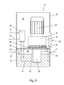
- a drive motor 31 drives a hydraulic pump 36, which is arranged in a sealing medium container 37, or which sucks sealing medium from the sealing medium container 37.
- the drive motor 31 simultaneously drives a fan 32 in the embodiment shown.
- fans 32 and hydraulic pump 36 are arranged axially one behind the other.
- the fan 32 could also be arranged separately and have its own drive motor.
- the hydraulic pump 36 could also be arranged outside the sealing medium container 37. All components of the hydraulic unit 12 are arranged in an aggregate housing 30.
- the hydraulic pump 36 sucks sealing medium from the sealing medium container 37 and conveys the sealing medium via a pressure line 41 to a hydraulic control unit 35, for controlling the pressure p oil of the sealing medium and / or the volume flow of the sealing medium.
- a hydraulic control unit 35 for controlling the pressure p oil of the sealing medium and / or the volume flow of the sealing medium.
- the sealing medium line 13 is connected to the hydraulic control unit 35.
- the discharge line 14 for returning the sealing medium from the sealing arrangement 10 may optionally be connected to the hydraulic control unit 35, for which purpose a sump line 42 leads from the hydraulic control unit 35 back into the sealing medium container 37.
- the discharge line 14 may also lead directly into the sealing medium container 37.
- the pressure p oil of the sealing medium can therefore also be adjusted by pressure control devices in the discharge line 14.
- the hydraulic control unit 35 can also be dispensed with.
- the drainage line 15 from the sealing arrangement 10 opens into the sealing medium container 37.
- a heat exchanger 33 For cooling the sealing medium in the sealing medium container 37 may be provided in the hydraulic unit 12, a heat exchanger 33, which is overflowed by the blown air flow of the fan 32 and is pumped through the sealing medium, as in Figure 3 indicated.
- the heat exchanger 33 is arranged, for example, between fan 32 and outlet slots 34 in the unit housing 30.
- a separate hydraulic pump may be provided.
- the sealing medium container 37 is arranged here in the lower part of the hydraulic unit 12 and by a separation part 38, e.g. a lid, completed. At the separation part 38 of the fan 32 and the drive motor 31 is arranged. At the separation part 38, a fan support 43 may be provided for this purpose, which rests on the separation part 38 and via which the fan 32 is attached to the separation part 38, e.g. by means of screws.
- a separation part 38 By the separation part 38, the interior of the hydraulic unit 12, and the unit housing 30, in the sealing medium container 37, which is partially filled with sealing medium, and in a fan chamber 39, in which at least the fan 32 is arranged, divided. Fan chamber 39 and sealing medium container 37 but can of course be separated locally and be provided with their own housing.
- the fan 32 sucks in air from the fan chamber 39 via intake slots 40 and blows out the intake air via outlet slots 34, possibly via the heat exchanger 33, to the outside.
- the separation part 38 is now a recess 44, for example, one or more holes, intended.
- the fan 32 sucks not only from the fan chamber 39, but to a certain extent from the sealing medium container 37, which in the free space 45 of the sealing medium container 37 (the space that is not filled with sealing medium) creates a negative pressure.
- the sealing medium container 37 would be connected in this case via the recess and a suitable, subsequent line with the fan chamber 39.
- This negative pressure is now used according to the invention to purge the compressor housing 2 with purge gas to keep the concentration of working fluid in the compressor housing 2 below a certain limit.
- the flushing takes place permanently when the fan 32 is running, wherein in the hydraulic unit, a controller for the operation of the fan 32, for example based on the temperature in the hydraulic unit or the temperature of the sealing medium may be provided.
- the fan 32 may also run permanently or coupled to the running times of the reciprocating compressor.
- the compressor housing 2 here e.g. the spacer 4, via a suction line 17 to the free space 45 in the sealing medium container 37 and thus connected to the negative pressure.
- the compressor housing 2 here e.g. in the spacer 4
- an opening 16 e.g. provided in the form of a suitable valve, which connects the compressor housing 2 with a purge gas reservoir 18, in the simplest case with the environment of the compressor, so that purge gas, in the simplest case ambient air, is sucked.
- the flushing amount can be adjusted by adjusting the negative pressure, e.g. be adjusted by appropriate dimensioning of the recess 44 in the separation part 38.
- the present in the hydraulic unit 12 fan 12 can therefore be used simultaneously for permanent flushing of the compressor housing.
- the recess 44 may preferably also be arranged in the region of the fan carrier 43, wherein in this case also a corresponding recess is provided in the fan carrier 43, as in Figure 3 indicated.
- the free space 45 in the sealing medium container 37 can be connected directly to the interior of the fan 32, whereby a particularly effective suction from the sealing medium container 37 can be achieved.
- the fan 32 is operated before the startup of the reciprocating compressor 1 for a certain period of time to flush the compressor housing 2 first, before the reciprocating compressor 1 is started.
- a gas sensor may also be arranged in the compressor housing 2 in order to prevent any inadmissible gas concentrations of working medium, e.g. occur in a fault of the flushing system, to detect and turn off the piston compressor, if necessary, or issue an error or warning message.
Landscapes
- Engineering & Computer Science (AREA)
- General Engineering & Computer Science (AREA)
- Mechanical Engineering (AREA)
- Compressor (AREA)
- Mechanical Sealing (AREA)
Applications Claiming Priority (1)
| Application Number | Priority Date | Filing Date | Title |
|---|---|---|---|
| ATA50608/2013A AT513836B1 (de) | 2013-09-23 | 2013-09-23 | Kompressor mit und Verfahren zur Spülung des Kompressorgehäuses mit Spülgas |
Publications (2)
| Publication Number | Publication Date |
|---|---|
| EP2853744A1 true EP2853744A1 (fr) | 2015-04-01 |
| EP2853744B1 EP2853744B1 (fr) | 2015-11-04 |
Family
ID=51300406
Family Applications (1)
| Application Number | Title | Priority Date | Filing Date |
|---|---|---|---|
| EP14182056.3A Not-in-force EP2853744B1 (fr) | 2013-09-23 | 2014-08-25 | Compresseur et procédé de rinçage d'un carter de compresseur à l'air de gaz de rinçage |
Country Status (5)
| Country | Link |
|---|---|
| US (1) | US9726169B2 (fr) |
| EP (1) | EP2853744B1 (fr) |
| JP (1) | JP2015061979A (fr) |
| CN (1) | CN104564604B (fr) |
| AT (1) | AT513836B1 (fr) |
Families Citing this family (15)
| Publication number | Priority date | Publication date | Assignee | Title |
|---|---|---|---|---|
| ITMI20142265A1 (it) * | 2014-12-29 | 2016-06-29 | Nuovo Pignone Srl | Dispositivo di tenuta per lo stelo di una valvola |
| DE102016005216A1 (de) * | 2016-04-28 | 2017-11-02 | Linde Aktiengesellschaft | Fluidenergiemaschine |
| IT201600085635A1 (it) * | 2016-08-17 | 2018-02-17 | Nuovo Pignone Tecnologie Srl | Tenuta per l'asta di un pistone |
| US11698062B2 (en) * | 2016-08-26 | 2023-07-11 | Burckhardt Compression Ag | Oil wiper packing |
| DE102016118728B4 (de) | 2016-10-04 | 2021-01-28 | Stasskol Gmbh | Abdichtvorrichtung, Kompressor mit einer Abdichtvorrichtung und Verfahren zum Abdichten einer Kolbenstange |
| CN107387486B (zh) * | 2017-08-01 | 2023-11-14 | 宁波斯达弗液压传动有限公司 | 一种集成式液压控制油缸 |
| US10865657B2 (en) * | 2018-04-23 | 2020-12-15 | Pratt & Whitney Canada Corp. | Sealing assembly for a gas turbine engine |
| EP3745002A1 (fr) * | 2019-05-31 | 2020-12-02 | Dana Motion Systems Italia S.R.L. | Système de transmission hydrostatique |
| CN110566673A (zh) * | 2019-09-29 | 2019-12-13 | 徐工集团工程机械股份有限公司科技分公司 | 一种介质隔离与密封防护系统及工程车辆 |
| IT202100019502A1 (it) * | 2021-07-22 | 2023-01-22 | Nuovo Pignone Tecnologie Srl | Un compressore alternativo con camera di riduzione della pressione e metodo |
| CN113915335A (zh) * | 2021-10-14 | 2022-01-11 | 安瑞科(蚌埠)压缩机有限公司 | 一种活塞式压缩机无泄漏密封装置 |
| DE102022202008A1 (de) * | 2022-02-28 | 2023-08-31 | Van Halteren Technologies Boxtel B.V. | Dichtungssystem für einen Verdichter und Verdichter |
| US12092093B2 (en) * | 2022-03-08 | 2024-09-17 | Air Products And Chemicals, Inc. | Apparatus and method for cryogenic pump cooldown |
| US12435716B2 (en) * | 2022-05-09 | 2025-10-07 | Hoerbiger Wien Gmbh | Pressure packing for a reciprocating piston compressor with buffer gas barrier |
| JP2024098377A (ja) * | 2023-01-10 | 2024-07-23 | 川崎重工業株式会社 | 水素ガス輸送装置および圧縮機のパージ方法 |
Citations (8)
| Publication number | Priority date | Publication date | Assignee | Title |
|---|---|---|---|---|
| FR553863A (fr) * | 1922-07-11 | 1923-06-01 | Westinghouse Freins | Perfectionnements dans la construction des pompes à air |
| US3685840A (en) * | 1971-03-29 | 1972-08-22 | Dresser Ind | Packing for compressors, pumps or the like |
| US4350349A (en) | 1981-02-12 | 1982-09-21 | Harry A. Robertson, Jr. | Rod packing |
| DE4122451C1 (en) * | 1991-07-06 | 1993-03-11 | Neuman & Esser Maschinenfabrik, 5132 Uebach-Palenberg, De | Stuffing box for toxic gas compressor - includes seals and flushing gas chambers with flushing gas connection tangential to piston rod |
| DE19709206A1 (de) * | 1997-03-06 | 1998-09-10 | Leybold Vakuum Gmbh | Vakuumpumpe |
| EP1146264A2 (fr) | 2000-04-10 | 2001-10-17 | Hoerbiger Kompressortechnik Services GmbH | Combinaison d'anneaux d'étanchéité |
| WO2010079227A1 (fr) | 2009-01-12 | 2010-07-15 | Hoerbiger Kompressortechnik Holding Gmbh | Dispositif d'étanchéité permettant de rendre étanche une tige de piston d'un compresseur à piston |
| EP2489907A1 (fr) | 2011-02-17 | 2012-08-22 | Hoerbiger Kompressortechnik Holding GmbH | Dispositif d'étanchéité pour une tige de piston à mouvement de va-et-vient d'un compresseur à piston |
Family Cites Families (9)
| Publication number | Priority date | Publication date | Assignee | Title |
|---|---|---|---|---|
| US2660367A (en) * | 1951-10-31 | 1953-11-24 | Allis Chalmers Mfg Co | Compressor sealing arrangement |
| GB1025384A (en) * | 1962-04-25 | 1966-04-06 | Nat Res Dev | Improvements in or relating to seals |
| JPS62153597A (ja) * | 1985-12-27 | 1987-07-08 | Hitachi Ltd | 真空ポンプ |
| CN86101455B (zh) * | 1986-03-03 | 1988-03-23 | 三菱重工业株式会社 | 回转流体机械的密封装置 |
| US5375853B1 (en) * | 1992-09-18 | 1998-05-05 | Crane John Inc | Gas lubricated barrier seal |
| US7118114B2 (en) * | 2003-05-15 | 2006-10-10 | Woodward Governor Company | Dynamic sealing arrangement for movable shaft |
| JP4391205B2 (ja) * | 2003-11-07 | 2009-12-24 | イーグル工業株式会社 | メカニカルシール装置 |
| JP5330896B2 (ja) * | 2009-05-20 | 2013-10-30 | 三菱重工業株式会社 | ドライ真空ポンプ |
| JP5638420B2 (ja) * | 2011-02-25 | 2014-12-10 | 三菱重工コンプレッサ株式会社 | オイルコンソール設備 |
-
2013
- 2013-09-23 AT ATA50608/2013A patent/AT513836B1/de not_active IP Right Cessation
-
2014
- 2014-08-25 EP EP14182056.3A patent/EP2853744B1/fr not_active Not-in-force
- 2014-09-10 US US14/482,161 patent/US9726169B2/en not_active Expired - Fee Related
- 2014-09-22 JP JP2014193020A patent/JP2015061979A/ja active Pending
- 2014-09-23 CN CN201410616569.0A patent/CN104564604B/zh not_active Expired - Fee Related
Patent Citations (8)
| Publication number | Priority date | Publication date | Assignee | Title |
|---|---|---|---|---|
| FR553863A (fr) * | 1922-07-11 | 1923-06-01 | Westinghouse Freins | Perfectionnements dans la construction des pompes à air |
| US3685840A (en) * | 1971-03-29 | 1972-08-22 | Dresser Ind | Packing for compressors, pumps or the like |
| US4350349A (en) | 1981-02-12 | 1982-09-21 | Harry A. Robertson, Jr. | Rod packing |
| DE4122451C1 (en) * | 1991-07-06 | 1993-03-11 | Neuman & Esser Maschinenfabrik, 5132 Uebach-Palenberg, De | Stuffing box for toxic gas compressor - includes seals and flushing gas chambers with flushing gas connection tangential to piston rod |
| DE19709206A1 (de) * | 1997-03-06 | 1998-09-10 | Leybold Vakuum Gmbh | Vakuumpumpe |
| EP1146264A2 (fr) | 2000-04-10 | 2001-10-17 | Hoerbiger Kompressortechnik Services GmbH | Combinaison d'anneaux d'étanchéité |
| WO2010079227A1 (fr) | 2009-01-12 | 2010-07-15 | Hoerbiger Kompressortechnik Holding Gmbh | Dispositif d'étanchéité permettant de rendre étanche une tige de piston d'un compresseur à piston |
| EP2489907A1 (fr) | 2011-02-17 | 2012-08-22 | Hoerbiger Kompressortechnik Holding GmbH | Dispositif d'étanchéité pour une tige de piston à mouvement de va-et-vient d'un compresseur à piston |
Also Published As
| Publication number | Publication date |
|---|---|
| AT513836B1 (de) | 2014-08-15 |
| CN104564604A (zh) | 2015-04-29 |
| EP2853744B1 (fr) | 2015-11-04 |
| JP2015061979A (ja) | 2015-04-02 |
| US20150086388A1 (en) | 2015-03-26 |
| CN104564604B (zh) | 2018-02-09 |
| US9726169B2 (en) | 2017-08-08 |
| AT513836A4 (de) | 2014-08-15 |
Similar Documents
| Publication | Publication Date | Title |
|---|---|---|
| EP2853744B1 (fr) | Compresseur et procédé de rinçage d'un carter de compresseur à l'air de gaz de rinçage | |
| EP3234415B1 (fr) | Dispositif d'étanchéité d'arbre d'une machine hydraulique et procédé d'étanchéité d'un arbre d'une machine hydraulique | |
| EP2855982B1 (fr) | Ensemble d'étanchéité permettant de rendre étanche une tige de piston à mouvement alternatif d'un compresseur à piston | |
| DE102011109930A1 (de) | Wälzlager und Vakuumpumpe mit Wälzlager | |
| WO1999057440A1 (fr) | Dispositif d'etancheite place sur un bout d'arbre d'un compresseur helicoidal a piston sec | |
| DE4438878A1 (de) | Dichtungssystem für eine vertikal angeordnete Welle | |
| DE102007053979A1 (de) | Vakuumpumpe mit Schmiermittelpumpe | |
| EP2791511B1 (fr) | Pompe à vide à anneau liquide pourvue d'un réglage de cavitation | |
| EP2738430A1 (fr) | Agencement d'étanchéité pour l'isolation étanche d'une tige de piston décrivant un mouvement de va-et-vient dans un compresseur à pistons | |
| EP3067560B1 (fr) | Pompe à vide dotée d'au moins un étage | |
| EP2440747B1 (fr) | Turbomachine | |
| EP2079151B1 (fr) | Procédé destiné au fonctionnement d'un générateur électrique pour la production d'énergie dans des centrales | |
| EP2824289A1 (fr) | Dispositif et procédé d'évacuation d'air de barrage dans un turboréacteur à double flux et turboréacteur à double flux associé | |
| DE102014211690A1 (de) | Fluidenergiemaschine, Verfahren zum Betrieb | |
| AT514335A4 (de) | Dichtanordnung zur Abdichtung einer hin- und hergehenden Kolbenstange eines Kolbenkompressors | |
| EP2816235B1 (fr) | Pompe à vide | |
| DE102013106469A1 (de) | Dichtungsvorrichtung | |
| DE102016118728A1 (de) | Abdichtvorrichtung, Kompressor mit einer Abdichtvorrichtung und Verfahren zum Abdichten einer Kolbenstange | |
| DE102012207019A1 (de) | Strömungsmaschine sowie Verfahren zur Kühlen einer solchen | |
| EP2990656A2 (fr) | Pompe à vide | |
| DE102008034948A1 (de) | Vakuumpumpe | |
| DE102015216192A1 (de) | Baugruppe mit Gleitringdichtung | |
| DE102013112024A1 (de) | Drehkolbengebläse mit einem Dichtsystem | |
| EP2187505A2 (fr) | Moteur électrique pour dispositifs de fermeture de bouteilles | |
| EP3267040B1 (fr) | Pompe turbomoléculaire |
Legal Events
| Date | Code | Title | Description |
|---|---|---|---|
| PUAI | Public reference made under article 153(3) epc to a published international application that has entered the european phase |
Free format text: ORIGINAL CODE: 0009012 |
|
| 17P | Request for examination filed |
Effective date: 20140825 |
|
| AK | Designated contracting states |
Kind code of ref document: A1 Designated state(s): AL AT BE BG CH CY CZ DE DK EE ES FI FR GB GR HR HU IE IS IT LI LT LU LV MC MK MT NL NO PL PT RO RS SE SI SK SM TR |
|
| AX | Request for extension of the european patent |
Extension state: BA ME |
|
| R17P | Request for examination filed (corrected) |
Effective date: 20150304 |
|
| RBV | Designated contracting states (corrected) |
Designated state(s): AL AT BE BG CH CY CZ DE DK EE ES FI FR GB GR HR HU IE IS IT LI LT LU LV MC MK MT NL NO PL PT RO RS SE SI SK SM TR |
|
| GRAP | Despatch of communication of intention to grant a patent |
Free format text: ORIGINAL CODE: EPIDOSNIGR1 |
|
| RIC1 | Information provided on ipc code assigned before grant |
Ipc: F04B 39/04 20060101AFI20150724BHEP |
|
| INTG | Intention to grant announced |
Effective date: 20150818 |
|
| GRAS | Grant fee paid |
Free format text: ORIGINAL CODE: EPIDOSNIGR3 |
|
| GRAA | (expected) grant |
Free format text: ORIGINAL CODE: 0009210 |
|
| AK | Designated contracting states |
Kind code of ref document: B1 Designated state(s): AL AT BE BG CH CY CZ DE DK EE ES FI FR GB GR HR HU IE IS IT LI LT LU LV MC MK MT NL NO PL PT RO RS SE SI SK SM TR |
|
| REG | Reference to a national code |
Ref country code: GB Ref legal event code: FG4D Free format text: NOT ENGLISH |
|
| REG | Reference to a national code |
Ref country code: CH Ref legal event code: EP |
|
| REG | Reference to a national code |
Ref country code: AT Ref legal event code: REF Ref document number: 759397 Country of ref document: AT Kind code of ref document: T Effective date: 20151115 |
|
| REG | Reference to a national code |
Ref country code: IE Ref legal event code: FG4D Free format text: LANGUAGE OF EP DOCUMENT: GERMAN |
|
| REG | Reference to a national code |
Ref country code: DE Ref legal event code: R096 Ref document number: 502014000181 Country of ref document: DE |
|
| REG | Reference to a national code |
Ref country code: CH Ref legal event code: NV Representative=s name: ISLER AND PEDRAZZINI AG, CH |
|
| REG | Reference to a national code |
Ref country code: NL Ref legal event code: MP Effective date: 20151104 |
|
| REG | Reference to a national code |
Ref country code: LT Ref legal event code: MG4D |
|
| PG25 | Lapsed in a contracting state [announced via postgrant information from national office to epo] |
Ref country code: IS Free format text: LAPSE BECAUSE OF FAILURE TO SUBMIT A TRANSLATION OF THE DESCRIPTION OR TO PAY THE FEE WITHIN THE PRESCRIBED TIME-LIMIT Effective date: 20160304 Ref country code: ES Free format text: LAPSE BECAUSE OF FAILURE TO SUBMIT A TRANSLATION OF THE DESCRIPTION OR TO PAY THE FEE WITHIN THE PRESCRIBED TIME-LIMIT Effective date: 20151104 Ref country code: LT Free format text: LAPSE BECAUSE OF FAILURE TO SUBMIT A TRANSLATION OF THE DESCRIPTION OR TO PAY THE FEE WITHIN THE PRESCRIBED TIME-LIMIT Effective date: 20151104 Ref country code: HR Free format text: LAPSE BECAUSE OF FAILURE TO SUBMIT A TRANSLATION OF THE DESCRIPTION OR TO PAY THE FEE WITHIN THE PRESCRIBED TIME-LIMIT Effective date: 20151104 Ref country code: NL Free format text: LAPSE BECAUSE OF FAILURE TO SUBMIT A TRANSLATION OF THE DESCRIPTION OR TO PAY THE FEE WITHIN THE PRESCRIBED TIME-LIMIT Effective date: 20151104 Ref country code: NO Free format text: LAPSE BECAUSE OF FAILURE TO SUBMIT A TRANSLATION OF THE DESCRIPTION OR TO PAY THE FEE WITHIN THE PRESCRIBED TIME-LIMIT Effective date: 20160204 |
|
| PG25 | Lapsed in a contracting state [announced via postgrant information from national office to epo] |
Ref country code: RS Free format text: LAPSE BECAUSE OF FAILURE TO SUBMIT A TRANSLATION OF THE DESCRIPTION OR TO PAY THE FEE WITHIN THE PRESCRIBED TIME-LIMIT Effective date: 20151104 Ref country code: SE Free format text: LAPSE BECAUSE OF FAILURE TO SUBMIT A TRANSLATION OF THE DESCRIPTION OR TO PAY THE FEE WITHIN THE PRESCRIBED TIME-LIMIT Effective date: 20151104 Ref country code: LV Free format text: LAPSE BECAUSE OF FAILURE TO SUBMIT A TRANSLATION OF THE DESCRIPTION OR TO PAY THE FEE WITHIN THE PRESCRIBED TIME-LIMIT Effective date: 20151104 Ref country code: FI Free format text: LAPSE BECAUSE OF FAILURE TO SUBMIT A TRANSLATION OF THE DESCRIPTION OR TO PAY THE FEE WITHIN THE PRESCRIBED TIME-LIMIT Effective date: 20151104 Ref country code: PT Free format text: LAPSE BECAUSE OF FAILURE TO SUBMIT A TRANSLATION OF THE DESCRIPTION OR TO PAY THE FEE WITHIN THE PRESCRIBED TIME-LIMIT Effective date: 20160304 Ref country code: PL Free format text: LAPSE BECAUSE OF FAILURE TO SUBMIT A TRANSLATION OF THE DESCRIPTION OR TO PAY THE FEE WITHIN THE PRESCRIBED TIME-LIMIT Effective date: 20151104 Ref country code: GR Free format text: LAPSE BECAUSE OF FAILURE TO SUBMIT A TRANSLATION OF THE DESCRIPTION OR TO PAY THE FEE WITHIN THE PRESCRIBED TIME-LIMIT Effective date: 20160205 |
|
| PG25 | Lapsed in a contracting state [announced via postgrant information from national office to epo] |
Ref country code: CZ Free format text: LAPSE BECAUSE OF FAILURE TO SUBMIT A TRANSLATION OF THE DESCRIPTION OR TO PAY THE FEE WITHIN THE PRESCRIBED TIME-LIMIT Effective date: 20151104 |
|
| REG | Reference to a national code |
Ref country code: DE Ref legal event code: R097 Ref document number: 502014000181 Country of ref document: DE |
|
| PG25 | Lapsed in a contracting state [announced via postgrant information from national office to epo] |
Ref country code: DK Free format text: LAPSE BECAUSE OF FAILURE TO SUBMIT A TRANSLATION OF THE DESCRIPTION OR TO PAY THE FEE WITHIN THE PRESCRIBED TIME-LIMIT Effective date: 20151104 Ref country code: EE Free format text: LAPSE BECAUSE OF FAILURE TO SUBMIT A TRANSLATION OF THE DESCRIPTION OR TO PAY THE FEE WITHIN THE PRESCRIBED TIME-LIMIT Effective date: 20151104 Ref country code: RO Free format text: LAPSE BECAUSE OF FAILURE TO SUBMIT A TRANSLATION OF THE DESCRIPTION OR TO PAY THE FEE WITHIN THE PRESCRIBED TIME-LIMIT Effective date: 20151104 Ref country code: SK Free format text: LAPSE BECAUSE OF FAILURE TO SUBMIT A TRANSLATION OF THE DESCRIPTION OR TO PAY THE FEE WITHIN THE PRESCRIBED TIME-LIMIT Effective date: 20151104 Ref country code: SM Free format text: LAPSE BECAUSE OF FAILURE TO SUBMIT A TRANSLATION OF THE DESCRIPTION OR TO PAY THE FEE WITHIN THE PRESCRIBED TIME-LIMIT Effective date: 20151104 |
|
| PLBE | No opposition filed within time limit |
Free format text: ORIGINAL CODE: 0009261 |
|
| STAA | Information on the status of an ep patent application or granted ep patent |
Free format text: STATUS: NO OPPOSITION FILED WITHIN TIME LIMIT |
|
| 26N | No opposition filed |
Effective date: 20160805 |
|
| PG25 | Lapsed in a contracting state [announced via postgrant information from national office to epo] |
Ref country code: SI Free format text: LAPSE BECAUSE OF FAILURE TO SUBMIT A TRANSLATION OF THE DESCRIPTION OR TO PAY THE FEE WITHIN THE PRESCRIBED TIME-LIMIT Effective date: 20151104 |
|
| PG25 | Lapsed in a contracting state [announced via postgrant information from national office to epo] |
Ref country code: BE Free format text: LAPSE BECAUSE OF NON-PAYMENT OF DUE FEES Effective date: 20160831 |
|
| PG25 | Lapsed in a contracting state [announced via postgrant information from national office to epo] |
Ref country code: MC Free format text: LAPSE BECAUSE OF FAILURE TO SUBMIT A TRANSLATION OF THE DESCRIPTION OR TO PAY THE FEE WITHIN THE PRESCRIBED TIME-LIMIT Effective date: 20151104 |
|
| REG | Reference to a national code |
Ref country code: FR Ref legal event code: ST Effective date: 20170428 |
|
| REG | Reference to a national code |
Ref country code: IE Ref legal event code: MM4A |
|
| PG25 | Lapsed in a contracting state [announced via postgrant information from national office to epo] |
Ref country code: FR Free format text: LAPSE BECAUSE OF NON-PAYMENT OF DUE FEES Effective date: 20160831 Ref country code: IE Free format text: LAPSE BECAUSE OF NON-PAYMENT OF DUE FEES Effective date: 20160825 |
|
| PG25 | Lapsed in a contracting state [announced via postgrant information from national office to epo] |
Ref country code: LU Free format text: LAPSE BECAUSE OF NON-PAYMENT OF DUE FEES Effective date: 20160825 |
|
| PG25 | Lapsed in a contracting state [announced via postgrant information from national office to epo] |
Ref country code: HU Free format text: LAPSE BECAUSE OF FAILURE TO SUBMIT A TRANSLATION OF THE DESCRIPTION OR TO PAY THE FEE WITHIN THE PRESCRIBED TIME-LIMIT; INVALID AB INITIO Effective date: 20140825 |
|
| PG25 | Lapsed in a contracting state [announced via postgrant information from national office to epo] |
Ref country code: CY Free format text: LAPSE BECAUSE OF FAILURE TO SUBMIT A TRANSLATION OF THE DESCRIPTION OR TO PAY THE FEE WITHIN THE PRESCRIBED TIME-LIMIT Effective date: 20151104 Ref country code: MT Free format text: LAPSE BECAUSE OF FAILURE TO SUBMIT A TRANSLATION OF THE DESCRIPTION OR TO PAY THE FEE WITHIN THE PRESCRIBED TIME-LIMIT Effective date: 20151104 Ref country code: MK Free format text: LAPSE BECAUSE OF FAILURE TO SUBMIT A TRANSLATION OF THE DESCRIPTION OR TO PAY THE FEE WITHIN THE PRESCRIBED TIME-LIMIT Effective date: 20151104 |
|
| PG25 | Lapsed in a contracting state [announced via postgrant information from national office to epo] |
Ref country code: BG Free format text: LAPSE BECAUSE OF FAILURE TO SUBMIT A TRANSLATION OF THE DESCRIPTION OR TO PAY THE FEE WITHIN THE PRESCRIBED TIME-LIMIT Effective date: 20151104 |
|
| PG25 | Lapsed in a contracting state [announced via postgrant information from national office to epo] |
Ref country code: AL Free format text: LAPSE BECAUSE OF FAILURE TO SUBMIT A TRANSLATION OF THE DESCRIPTION OR TO PAY THE FEE WITHIN THE PRESCRIBED TIME-LIMIT Effective date: 20151104 Ref country code: TR Free format text: LAPSE BECAUSE OF FAILURE TO SUBMIT A TRANSLATION OF THE DESCRIPTION OR TO PAY THE FEE WITHIN THE PRESCRIBED TIME-LIMIT Effective date: 20151104 |
|
| PGFP | Annual fee paid to national office [announced via postgrant information from national office to epo] |
Ref country code: DE Payment date: 20180921 Year of fee payment: 5 Ref country code: IT Payment date: 20180830 Year of fee payment: 5 |
|
| PGFP | Annual fee paid to national office [announced via postgrant information from national office to epo] |
Ref country code: GB Payment date: 20180822 Year of fee payment: 5 Ref country code: CH Payment date: 20180822 Year of fee payment: 5 |
|
| REG | Reference to a national code |
Ref country code: DE Ref legal event code: R119 Ref document number: 502014000181 Country of ref document: DE |
|
| GBPC | Gb: european patent ceased through non-payment of renewal fee |
Effective date: 20190825 |
|
| PG25 | Lapsed in a contracting state [announced via postgrant information from national office to epo] |
Ref country code: CH Free format text: LAPSE BECAUSE OF NON-PAYMENT OF DUE FEES Effective date: 20190831 Ref country code: LI Free format text: LAPSE BECAUSE OF NON-PAYMENT OF DUE FEES Effective date: 20190831 |
|
| PG25 | Lapsed in a contracting state [announced via postgrant information from national office to epo] |
Ref country code: DE Free format text: LAPSE BECAUSE OF NON-PAYMENT OF DUE FEES Effective date: 20200303 |
|
| PG25 | Lapsed in a contracting state [announced via postgrant information from national office to epo] |
Ref country code: GB Free format text: LAPSE BECAUSE OF NON-PAYMENT OF DUE FEES Effective date: 20190825 Ref country code: IT Free format text: LAPSE BECAUSE OF NON-PAYMENT OF DUE FEES Effective date: 20190825 |
|
| REG | Reference to a national code |
Ref country code: AT Ref legal event code: MM01 Ref document number: 759397 Country of ref document: AT Kind code of ref document: T Effective date: 20190825 |
|
| PG25 | Lapsed in a contracting state [announced via postgrant information from national office to epo] |
Ref country code: AT Free format text: LAPSE BECAUSE OF NON-PAYMENT OF DUE FEES Effective date: 20190825 |