EP2853766A2 - Couplage de rampes sphériques guidées sur un arbre de commande - Google Patents
Couplage de rampes sphériques guidées sur un arbre de commande Download PDFInfo
- Publication number
- EP2853766A2 EP2853766A2 EP14184356.5A EP14184356A EP2853766A2 EP 2853766 A2 EP2853766 A2 EP 2853766A2 EP 14184356 A EP14184356 A EP 14184356A EP 2853766 A2 EP2853766 A2 EP 2853766A2
- Authority
- EP
- European Patent Office
- Prior art keywords
- ramp
- ball
- coupling according
- disc
- ball ramp
- Prior art date
- Legal status (The legal status is an assumption and is not a legal conclusion. Google has not performed a legal analysis and makes no representation as to the accuracy of the status listed.)
- Granted
Links
Images

Classifications
-
- F—MECHANICAL ENGINEERING; LIGHTING; HEATING; WEAPONS; BLASTING
- F16—ENGINEERING ELEMENTS AND UNITS; GENERAL MEASURES FOR PRODUCING AND MAINTAINING EFFECTIVE FUNCTIONING OF MACHINES OR INSTALLATIONS; THERMAL INSULATION IN GENERAL
- F16D—COUPLINGS FOR TRANSMITTING ROTATION; CLUTCHES; BRAKES
- F16D65/00—Parts or details
- F16D65/38—Slack adjusters
- F16D65/40—Slack adjusters mechanical
- F16D65/52—Slack adjusters mechanical self-acting in one direction for adjusting excessive play
- F16D65/56—Slack adjusters mechanical self-acting in one direction for adjusting excessive play with screw-thread and nut
- F16D65/567—Slack adjusters mechanical self-acting in one direction for adjusting excessive play with screw-thread and nut for mounting on a disc brake
-
- F—MECHANICAL ENGINEERING; LIGHTING; HEATING; WEAPONS; BLASTING
- F16—ENGINEERING ELEMENTS AND UNITS; GENERAL MEASURES FOR PRODUCING AND MAINTAINING EFFECTIVE FUNCTIONING OF MACHINES OR INSTALLATIONS; THERMAL INSULATION IN GENERAL
- F16D—COUPLINGS FOR TRANSMITTING ROTATION; CLUTCHES; BRAKES
- F16D65/00—Parts or details
- F16D65/14—Actuating mechanisms for brakes; Means for initiating operation at a predetermined position
- F16D65/16—Actuating mechanisms for brakes; Means for initiating operation at a predetermined position arranged in or on the brake
- F16D65/18—Actuating mechanisms for brakes; Means for initiating operation at a predetermined position arranged in or on the brake adapted for drawing members together, e.g. for disc brakes
-
- F—MECHANICAL ENGINEERING; LIGHTING; HEATING; WEAPONS; BLASTING
- F16—ENGINEERING ELEMENTS AND UNITS; GENERAL MEASURES FOR PRODUCING AND MAINTAINING EFFECTIVE FUNCTIONING OF MACHINES OR INSTALLATIONS; THERMAL INSULATION IN GENERAL
- F16D—COUPLINGS FOR TRANSMITTING ROTATION; CLUTCHES; BRAKES
- F16D2121/00—Type of actuator operation force
- F16D2121/14—Mechanical
-
- F—MECHANICAL ENGINEERING; LIGHTING; HEATING; WEAPONS; BLASTING
- F16—ENGINEERING ELEMENTS AND UNITS; GENERAL MEASURES FOR PRODUCING AND MAINTAINING EFFECTIVE FUNCTIONING OF MACHINES OR INSTALLATIONS; THERMAL INSULATION IN GENERAL
- F16D—COUPLINGS FOR TRANSMITTING ROTATION; CLUTCHES; BRAKES
- F16D2125/00—Components of actuators
- F16D2125/18—Mechanical mechanisms
- F16D2125/20—Mechanical mechanisms converting rotation to linear movement or vice versa
- F16D2125/34—Mechanical mechanisms converting rotation to linear movement or vice versa acting in the direction of the axis of rotation
- F16D2125/36—Helical cams, Ball-rotating ramps
Definitions
- the invention relates to a spring-loaded on a drive spindle, in particular an adjusting device of a disc brake guided ball ramp clutch.
- Such ball ramp coupling is from the DE 10 2004 037 771 A1 known.
- this ball ramp clutch is part of an adjusting device, with a wear-related clearance change is compensated.
- adjusting device In the known adjusting device is arranged in the interior of a threaded sleeve which acts as a brake stamp and which is rotatably held in a bridge of the disc brake.
- the adjusting device Via a drive element, for example via a shift fork, the adjusting device is driven by a brake lever, wherein when a predetermined torque is exceeded, the ball ramp clutch acts as overload protection function, so that a further rotation of the threaded sleeve does not occur.
- the ball ramp clutch has two ramp discs, of which a brake pad facing against rotation is connected to a form-fitting into the threaded tube spring sleeve, while the other ramp disc engages the shift fork or even forms the shift fork.
- each dome is followed by a rising ramp, with the ramps of the opposing ramp disks being oriented in opposite directions.
- the thickness of the disc-shaped cage is determined by the gap formed between the two ramp discs in non-functional position, that is, when the balls are in the respective calotte, there is no sufficient contact surface for the balls.
- this cage is therefore completely unsuitable.
- the invention has for its object to further develop a ball ramp coupling of the generic type so that their reliability improves and their life is increased.
- the improved reliability also includes returning all the balls to their home position when the disengagement is canceled and the two ramp discs are again brought into a clutch state.
- the cage in which the balls are held consists of an annular disc with cup-shaped receptacles for the balls, wherein these receptacles are designed so that the balls eino in the circumferential direction of the annular disc with little play.
- the receptacles are designed so that the balls are held securely, wherein it is ensured that the cage is held in the axial direction of the center of the ball.
- the two opposite sides of the ramp discs associated hump-shaped elevations of the cage are preferably designed as freeform surfaces corresponding to the ramp geometry of the ramp discs, whereby a sufficient material for the ball guide is available.
- the invention makes use of the space available in the coupling state of the associated ramp, which provides space for the survey and thus a much larger contact surface for the ball.
- the both sides of the radial surfaces of the cage projecting elevations of a recording in their overall height smaller than the diameter of the ball.
- the sheet metal part which forms a core, ensures the necessary strength over the life of the cage, especially in the field of design-related low material accumulations.
- positive locking means may be provided, for example in the form of holes in the sheet metal part, which are penetrated by the plastic. It is also conceivable to make the surface of the sheet metal part liable adhesion, with undercuts or roughening, for example by shot peening or the like.
- FIG. 1 an adjustment of a disc brake for a commercial vehicle whose function in the DE 10 2004 037 771 A1 is described in detail and to which reference is made.
- the adjusting device has a drive spindle 1, on which at one end a toothing 6 is provided to attack a tool to turn back the drive spindle 1 in a brake pad change.
- the adjusting device as a whole is fixed by means of a bearing plate 5 on a brake caliper of the disc brake.
- the spring sleeve 2 To adjust a brake sleeve forming a threaded sleeve, the spring sleeve 2 at its end facing away from the toothing 5 driving webs 4, which engage positively in the threaded sleeve.
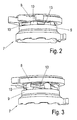
- a ball ramp clutch 7 On the drive shaft 1, a ball ramp clutch 7 is further guided, with two ramp discs 8, 9, which are each provided on their sides facing each other with calotte 11, which are distributed over the circumference and in each of which a ball 10 rests.
- Each dome 11 is adjoined by a ramp 12 which increases in the circumferential direction, the ramps 12 of the opposite ramp disks 8, 9 being aligned in opposite directions.
- the spring sleeve 2 is rotated via the ball ramp clutch 7, to which a brake lever engages in the form of a shift fork ramp plate 8.
- a disc-shaped cage 13 accommodating the balls 10 is arranged between the ramp discs 8, 9, corresponding to the illustration in FIGS FIGS. 2 and 3 , While the FIG. 2 a starting position reproduces, so to speak, in which the positive connection between the two ramp discs 8 and 9 is made by the balls, gives the FIG. 3 an end position again, in which the balls 10 are brought over the ramps 12 rising except positive engagement.
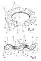
- the cage 13 is recognizable as a detail.
- Distributed circumferentially open receptacles 14 are provided to the outer edge, which, as can be seen from the FIG. 5 results, pocket-like are formed with contact surfaces 16 for the balls 10th
- a core 19 is surrounded by a sheet metal part on the outside of plastic, with small holes 15 are intended for fixing the sheet metal part in the injection molding tool, but which can also be used as an ejector.
- Each of the circumferentially opposite contact surfaces 16 of each receptacle 14 protrudes on one side over one of the two radial surfaces 18 of the cage 13, wherein the contact surfaces 16 are each formed in an integrally formed hump-shaped elevation 17.
- Each elevation 17 of a receptacle 14 is associated with one of the two opposite ramp discs 8, 9, that is, the elevations 17 and thus the molded contact surfaces 16 extend in the opposite direction in the axial direction, with respect to the axis of the cage thirteenth
- the elevations 17 are formed as free-form surfaces corresponding to the surface geometry of the associated ramps of the adjacent ramp discs 8.9.
- the free-form surfaces are in the dimension z ( FIG. 5 ) designed so that the balls 10, based on the drive spindle 1, eino in the radial direction with little play.
Landscapes
- Engineering & Computer Science (AREA)
- General Engineering & Computer Science (AREA)
- Mechanical Engineering (AREA)
- Braking Arrangements (AREA)
Applications Claiming Priority (1)
| Application Number | Priority Date | Filing Date | Title |
|---|---|---|---|
| DE102013110638.2A DE102013110638A1 (de) | 2013-09-26 | 2013-09-26 | Auf einer Antriebsspindel geführte Kugelrampenkupplung |
Publications (3)
| Publication Number | Publication Date |
|---|---|
| EP2853766A2 true EP2853766A2 (fr) | 2015-04-01 |
| EP2853766A3 EP2853766A3 (fr) | 2016-08-10 |
| EP2853766B1 EP2853766B1 (fr) | 2019-12-18 |
Family
ID=51518652
Family Applications (1)
| Application Number | Title | Priority Date | Filing Date |
|---|---|---|---|
| EP14184356.5A Active EP2853766B1 (fr) | 2013-09-26 | 2014-09-11 | Couplage de rampes sphériques guidées sur un arbre de commande |
Country Status (2)
| Country | Link |
|---|---|
| EP (1) | EP2853766B1 (fr) |
| DE (1) | DE102013110638A1 (fr) |
Families Citing this family (2)
| Publication number | Priority date | Publication date | Assignee | Title |
|---|---|---|---|---|
| DE102015205923B3 (de) | 2015-04-01 | 2016-06-09 | Magna Auteca Ag | Abklappantrieb sowie Außenspiegel zum Abklappen |
| DE102020211973A1 (de) * | 2020-09-24 | 2022-03-24 | Zf Friedrichshafen Ag | Betätigungsvorrichtung für ein Getriebe |
Citations (2)
| Publication number | Priority date | Publication date | Assignee | Title |
|---|---|---|---|---|
| DE102004037771A1 (de) | 2004-08-04 | 2006-03-16 | Knorr-Bremse Systeme für Nutzfahrzeuge GmbH | Nachstellvorrichtung für eine pneumatisch betätigte Scheibenbremse |
| DE102009052189A1 (de) | 2009-11-06 | 2011-05-19 | Neo-Plastic Dr. Doetsch Diespeck Gmbh | Wälzkörper-Käfigring |
Family Cites Families (5)
| Publication number | Priority date | Publication date | Assignee | Title |
|---|---|---|---|---|
| CH372509A (de) * | 1957-11-11 | 1963-10-15 | Robert Kling Wetzlar Gmbh | Kunststoffkäfig für Wälzlager |
| DE7016959U (de) * | 1970-05-06 | 1972-03-30 | Koepke Wolfgang | Waelzlager zur aufnahme von bewegungen, insbesondere drehbewegungen. |
| US5038895A (en) * | 1988-10-24 | 1991-08-13 | Kelsey-Hayes Company | Automatic adjusting mechanism for a disc brake assembly having a mechanically actuated parking brake |
| DE102009018224A1 (de) * | 2009-04-21 | 2010-11-11 | Knorr-Bremse Systeme für Nutzfahrzeuge GmbH | Mehrscheibenbremse |
| JP5148668B2 (ja) * | 2010-01-26 | 2013-02-20 | 曙ブレーキ工業株式会社 | パーキング機構付ディスクブレーキ装置 |
-
2013
- 2013-09-26 DE DE102013110638.2A patent/DE102013110638A1/de not_active Ceased
-
2014
- 2014-09-11 EP EP14184356.5A patent/EP2853766B1/fr active Active
Patent Citations (2)
| Publication number | Priority date | Publication date | Assignee | Title |
|---|---|---|---|---|
| DE102004037771A1 (de) | 2004-08-04 | 2006-03-16 | Knorr-Bremse Systeme für Nutzfahrzeuge GmbH | Nachstellvorrichtung für eine pneumatisch betätigte Scheibenbremse |
| DE102009052189A1 (de) | 2009-11-06 | 2011-05-19 | Neo-Plastic Dr. Doetsch Diespeck Gmbh | Wälzkörper-Käfigring |
Also Published As
| Publication number | Publication date |
|---|---|
| EP2853766B1 (fr) | 2019-12-18 |
| DE102013110638A1 (de) | 2015-03-26 |
| EP2853766A3 (fr) | 2016-08-10 |
Similar Documents
| Publication | Publication Date | Title |
|---|---|---|
| DE102007028948B3 (de) | Werkzeug zur Montage eines Maschinenelementes | |
| EP2102521A1 (fr) | Frein à disque | |
| EP3362699B1 (fr) | Dispositif de surveillance pour frein à disque d'un véhicule automobile | |
| EP2363317B1 (fr) | Roue libre de galet de serrage pour un dispositif de réglage dans un véhicule automobile | |
| WO2014026686A1 (fr) | Dispositif d'immobilisation pendant le transport, destiné notamment au piston d'une butée de débrayage | |
| EP3377784B1 (fr) | Ensemble d'amortissement pour au moins une masse d'amortissement | |
| WO2013020744A1 (fr) | Dispositif de commande d'une boîte de vitesses de véhicule automobile et procédé de fabrication de ce dispositif | |
| DE102015000192B4 (de) | Brems-Rasteinheit für Kommandogeber | |
| DE102012112610A1 (de) | Rastbolzen | |
| EP2853766A2 (fr) | Couplage de rampes sphériques guidées sur un arbre de commande | |
| WO2015014358A1 (fr) | Bague de rampe pour un système de rampe d'un dispositif d'ajustement ainsi que procédé servant au montage d'un embrayage de friction | |
| DE10311618A1 (de) | Luftgebläse mit einem mit dem Motorgehäuse nicht in Berührung bringbaren Lüfter | |
| EP3779229B1 (fr) | Bague d'accouplement | |
| DE102011051073A1 (de) | Vorrichtung zum Nachstellen des verschleißbedingten Lüftspiels bei einer Fahrzeugbremse | |
| DE102009021874A1 (de) | Vorspanneinheit | |
| DE102014223545A1 (de) | Rampensystem für eine Nachstelleinrichtung | |
| DE112014003745B4 (de) | Klinkenfreilauf | |
| DE102014018262A1 (de) | Signalgeberring für einen Magnetsensor und Gurtaufroller mit einem Signalgeberring | |
| DE102014201019A1 (de) | Ausrücksystem | |
| DE102010025458A1 (de) | Reibungskupplung | |
| DE102017121807A1 (de) | Nehmerzylinder mit Taumelausgleich im Dichtungsträger | |
| WO2016112889A1 (fr) | Dispositif de debrayage | |
| DE102014212027A1 (de) | Rampenring für eine Nachstelleinrichtung | |
| DE102019002747A1 (de) | Kupplung für einen Elektromotor und Elektromotor mit Rotorwelle, Winkelsensor und Kupplung | |
| EP2599644B1 (fr) | Composant de roulettes avec installation de stockage pouvant être bloquée |
Legal Events
| Date | Code | Title | Description |
|---|---|---|---|
| PUAI | Public reference made under article 153(3) epc to a published international application that has entered the european phase |
Free format text: ORIGINAL CODE: 0009012 |
|
| 17P | Request for examination filed |
Effective date: 20140911 |
|
| AK | Designated contracting states |
Kind code of ref document: A2 Designated state(s): AL AT BE BG CH CY CZ DE DK EE ES FI FR GB GR HR HU IE IS IT LI LT LU LV MC MK MT NL NO PL PT RO RS SE SI SK SM TR |
|
| AX | Request for extension of the european patent |
Extension state: BA ME |
|
| PUAL | Search report despatched |
Free format text: ORIGINAL CODE: 0009013 |
|
| AK | Designated contracting states |
Kind code of ref document: A3 Designated state(s): AL AT BE BG CH CY CZ DE DK EE ES FI FR GB GR HR HU IE IS IT LI LT LU LV MC MK MT NL NO PL PT RO RS SE SI SK SM TR |
|
| AX | Request for extension of the european patent |
Extension state: BA ME |
|
| RIC1 | Information provided on ipc code assigned before grant |
Ipc: F16D 65/56 20060101ALI20160705BHEP Ipc: F16D 65/18 20060101AFI20160705BHEP |
|
| STAA | Information on the status of an ep patent application or granted ep patent |
Free format text: STATUS: REQUEST FOR EXAMINATION WAS MADE |
|
| R17P | Request for examination filed (corrected) |
Effective date: 20170210 |
|
| RBV | Designated contracting states (corrected) |
Designated state(s): AL AT BE BG CH CY CZ DE DK EE ES FI FR GB GR HR HU IE IS IT LI LT LU LV MC MK MT NL NO PL PT RO RS SE SI SK SM TR |
|
| GRAP | Despatch of communication of intention to grant a patent |
Free format text: ORIGINAL CODE: EPIDOSNIGR1 |
|
| STAA | Information on the status of an ep patent application or granted ep patent |
Free format text: STATUS: GRANT OF PATENT IS INTENDED |
|
| INTG | Intention to grant announced |
Effective date: 20190711 |
|
| GRAS | Grant fee paid |
Free format text: ORIGINAL CODE: EPIDOSNIGR3 |
|
| GRAA | (expected) grant |
Free format text: ORIGINAL CODE: 0009210 |
|
| STAA | Information on the status of an ep patent application or granted ep patent |
Free format text: STATUS: THE PATENT HAS BEEN GRANTED |
|
| AK | Designated contracting states |
Kind code of ref document: B1 Designated state(s): AL AT BE BG CH CY CZ DE DK EE ES FI FR GB GR HR HU IE IS IT LI LT LU LV MC MK MT NL NO PL PT RO RS SE SI SK SM TR |
|
| REG | Reference to a national code |
Ref country code: CH Ref legal event code: EP |
|
| REG | Reference to a national code |
Ref country code: DE Ref legal event code: R096 Ref document number: 502014013271 Country of ref document: DE |
|
| REG | Reference to a national code |
Ref country code: IE Ref legal event code: FG4D Free format text: LANGUAGE OF EP DOCUMENT: GERMAN |
|
| REG | Reference to a national code |
Ref country code: AT Ref legal event code: REF Ref document number: 1214948 Country of ref document: AT Kind code of ref document: T Effective date: 20200115 |
|
| REG | Reference to a national code |
Ref country code: SE Ref legal event code: TRGR |
|
| REG | Reference to a national code |
Ref country code: NL Ref legal event code: MP Effective date: 20191218 |
|
| PG25 | Lapsed in a contracting state [announced via postgrant information from national office to epo] |
Ref country code: LV Free format text: LAPSE BECAUSE OF FAILURE TO SUBMIT A TRANSLATION OF THE DESCRIPTION OR TO PAY THE FEE WITHIN THE PRESCRIBED TIME-LIMIT Effective date: 20191218 Ref country code: BG Free format text: LAPSE BECAUSE OF FAILURE TO SUBMIT A TRANSLATION OF THE DESCRIPTION OR TO PAY THE FEE WITHIN THE PRESCRIBED TIME-LIMIT Effective date: 20200318 Ref country code: NO Free format text: LAPSE BECAUSE OF FAILURE TO SUBMIT A TRANSLATION OF THE DESCRIPTION OR TO PAY THE FEE WITHIN THE PRESCRIBED TIME-LIMIT Effective date: 20200318 Ref country code: FI Free format text: LAPSE BECAUSE OF FAILURE TO SUBMIT A TRANSLATION OF THE DESCRIPTION OR TO PAY THE FEE WITHIN THE PRESCRIBED TIME-LIMIT Effective date: 20191218 Ref country code: LT Free format text: LAPSE BECAUSE OF FAILURE TO SUBMIT A TRANSLATION OF THE DESCRIPTION OR TO PAY THE FEE WITHIN THE PRESCRIBED TIME-LIMIT Effective date: 20191218 Ref country code: GR Free format text: LAPSE BECAUSE OF FAILURE TO SUBMIT A TRANSLATION OF THE DESCRIPTION OR TO PAY THE FEE WITHIN THE PRESCRIBED TIME-LIMIT Effective date: 20200319 |
|
| REG | Reference to a national code |
Ref country code: LT Ref legal event code: MG4D |
|
| PG25 | Lapsed in a contracting state [announced via postgrant information from national office to epo] |
Ref country code: HR Free format text: LAPSE BECAUSE OF FAILURE TO SUBMIT A TRANSLATION OF THE DESCRIPTION OR TO PAY THE FEE WITHIN THE PRESCRIBED TIME-LIMIT Effective date: 20191218 Ref country code: RS Free format text: LAPSE BECAUSE OF FAILURE TO SUBMIT A TRANSLATION OF THE DESCRIPTION OR TO PAY THE FEE WITHIN THE PRESCRIBED TIME-LIMIT Effective date: 20191218 |
|
| PG25 | Lapsed in a contracting state [announced via postgrant information from national office to epo] |
Ref country code: AL Free format text: LAPSE BECAUSE OF FAILURE TO SUBMIT A TRANSLATION OF THE DESCRIPTION OR TO PAY THE FEE WITHIN THE PRESCRIBED TIME-LIMIT Effective date: 20191218 |
|
| PG25 | Lapsed in a contracting state [announced via postgrant information from national office to epo] |
Ref country code: RO Free format text: LAPSE BECAUSE OF FAILURE TO SUBMIT A TRANSLATION OF THE DESCRIPTION OR TO PAY THE FEE WITHIN THE PRESCRIBED TIME-LIMIT Effective date: 20191218 Ref country code: CZ Free format text: LAPSE BECAUSE OF FAILURE TO SUBMIT A TRANSLATION OF THE DESCRIPTION OR TO PAY THE FEE WITHIN THE PRESCRIBED TIME-LIMIT Effective date: 20191218 Ref country code: EE Free format text: LAPSE BECAUSE OF FAILURE TO SUBMIT A TRANSLATION OF THE DESCRIPTION OR TO PAY THE FEE WITHIN THE PRESCRIBED TIME-LIMIT Effective date: 20191218 Ref country code: PT Free format text: LAPSE BECAUSE OF FAILURE TO SUBMIT A TRANSLATION OF THE DESCRIPTION OR TO PAY THE FEE WITHIN THE PRESCRIBED TIME-LIMIT Effective date: 20200513 Ref country code: NL Free format text: LAPSE BECAUSE OF FAILURE TO SUBMIT A TRANSLATION OF THE DESCRIPTION OR TO PAY THE FEE WITHIN THE PRESCRIBED TIME-LIMIT Effective date: 20191218 |
|
| PG25 | Lapsed in a contracting state [announced via postgrant information from national office to epo] |
Ref country code: SM Free format text: LAPSE BECAUSE OF FAILURE TO SUBMIT A TRANSLATION OF THE DESCRIPTION OR TO PAY THE FEE WITHIN THE PRESCRIBED TIME-LIMIT Effective date: 20191218 Ref country code: SK Free format text: LAPSE BECAUSE OF FAILURE TO SUBMIT A TRANSLATION OF THE DESCRIPTION OR TO PAY THE FEE WITHIN THE PRESCRIBED TIME-LIMIT Effective date: 20191218 Ref country code: IS Free format text: LAPSE BECAUSE OF FAILURE TO SUBMIT A TRANSLATION OF THE DESCRIPTION OR TO PAY THE FEE WITHIN THE PRESCRIBED TIME-LIMIT Effective date: 20200418 |
|
| REG | Reference to a national code |
Ref country code: DE Ref legal event code: R097 Ref document number: 502014013271 Country of ref document: DE |
|
| PLBE | No opposition filed within time limit |
Free format text: ORIGINAL CODE: 0009261 |
|
| STAA | Information on the status of an ep patent application or granted ep patent |
Free format text: STATUS: NO OPPOSITION FILED WITHIN TIME LIMIT |
|
| PG25 | Lapsed in a contracting state [announced via postgrant information from national office to epo] |
Ref country code: DK Free format text: LAPSE BECAUSE OF FAILURE TO SUBMIT A TRANSLATION OF THE DESCRIPTION OR TO PAY THE FEE WITHIN THE PRESCRIBED TIME-LIMIT Effective date: 20191218 Ref country code: ES Free format text: LAPSE BECAUSE OF FAILURE TO SUBMIT A TRANSLATION OF THE DESCRIPTION OR TO PAY THE FEE WITHIN THE PRESCRIBED TIME-LIMIT Effective date: 20191218 |
|
| 26N | No opposition filed |
Effective date: 20200921 |
|
| PG25 | Lapsed in a contracting state [announced via postgrant information from national office to epo] |
Ref country code: SI Free format text: LAPSE BECAUSE OF FAILURE TO SUBMIT A TRANSLATION OF THE DESCRIPTION OR TO PAY THE FEE WITHIN THE PRESCRIBED TIME-LIMIT Effective date: 20191218 |
|
| PG25 | Lapsed in a contracting state [announced via postgrant information from national office to epo] |
Ref country code: PL Free format text: LAPSE BECAUSE OF FAILURE TO SUBMIT A TRANSLATION OF THE DESCRIPTION OR TO PAY THE FEE WITHIN THE PRESCRIBED TIME-LIMIT Effective date: 20191218 |
|
| PG25 | Lapsed in a contracting state [announced via postgrant information from national office to epo] |
Ref country code: MC Free format text: LAPSE BECAUSE OF FAILURE TO SUBMIT A TRANSLATION OF THE DESCRIPTION OR TO PAY THE FEE WITHIN THE PRESCRIBED TIME-LIMIT Effective date: 20191218 |
|
| REG | Reference to a national code |
Ref country code: CH Ref legal event code: PL |
|
| REG | Reference to a national code |
Ref country code: BE Ref legal event code: MM Effective date: 20200930 |
|
| PG25 | Lapsed in a contracting state [announced via postgrant information from national office to epo] |
Ref country code: LU Free format text: LAPSE BECAUSE OF NON-PAYMENT OF DUE FEES Effective date: 20200911 |
|
| PG25 | Lapsed in a contracting state [announced via postgrant information from national office to epo] |
Ref country code: FR Free format text: LAPSE BECAUSE OF NON-PAYMENT OF DUE FEES Effective date: 20200930 |
|
| PG25 | Lapsed in a contracting state [announced via postgrant information from national office to epo] |
Ref country code: CH Free format text: LAPSE BECAUSE OF NON-PAYMENT OF DUE FEES Effective date: 20200930 Ref country code: BE Free format text: LAPSE BECAUSE OF NON-PAYMENT OF DUE FEES Effective date: 20200930 Ref country code: LI Free format text: LAPSE BECAUSE OF NON-PAYMENT OF DUE FEES Effective date: 20200930 Ref country code: IE Free format text: LAPSE BECAUSE OF NON-PAYMENT OF DUE FEES Effective date: 20200911 |
|
| REG | Reference to a national code |
Ref country code: AT Ref legal event code: MM01 Ref document number: 1214948 Country of ref document: AT Kind code of ref document: T Effective date: 20200911 |
|
| PG25 | Lapsed in a contracting state [announced via postgrant information from national office to epo] |
Ref country code: AT Free format text: LAPSE BECAUSE OF NON-PAYMENT OF DUE FEES Effective date: 20200911 |
|
| PG25 | Lapsed in a contracting state [announced via postgrant information from national office to epo] |
Ref country code: TR Free format text: LAPSE BECAUSE OF FAILURE TO SUBMIT A TRANSLATION OF THE DESCRIPTION OR TO PAY THE FEE WITHIN THE PRESCRIBED TIME-LIMIT Effective date: 20191218 Ref country code: MT Free format text: LAPSE BECAUSE OF FAILURE TO SUBMIT A TRANSLATION OF THE DESCRIPTION OR TO PAY THE FEE WITHIN THE PRESCRIBED TIME-LIMIT Effective date: 20191218 Ref country code: CY Free format text: LAPSE BECAUSE OF FAILURE TO SUBMIT A TRANSLATION OF THE DESCRIPTION OR TO PAY THE FEE WITHIN THE PRESCRIBED TIME-LIMIT Effective date: 20191218 |
|
| PG25 | Lapsed in a contracting state [announced via postgrant information from national office to epo] |
Ref country code: MK Free format text: LAPSE BECAUSE OF FAILURE TO SUBMIT A TRANSLATION OF THE DESCRIPTION OR TO PAY THE FEE WITHIN THE PRESCRIBED TIME-LIMIT Effective date: 20191218 |
|
| P01 | Opt-out of the competence of the unified patent court (upc) registered |
Effective date: 20230607 |
|
| PGFP | Annual fee paid to national office [announced via postgrant information from national office to epo] |
Ref country code: DE Payment date: 20250926 Year of fee payment: 12 |
|
| PGFP | Annual fee paid to national office [announced via postgrant information from national office to epo] |
Ref country code: IT Payment date: 20250919 Year of fee payment: 12 |
|
| PGFP | Annual fee paid to national office [announced via postgrant information from national office to epo] |
Ref country code: GB Payment date: 20250923 Year of fee payment: 12 |
|
| PGFP | Annual fee paid to national office [announced via postgrant information from national office to epo] |
Ref country code: SE Payment date: 20250924 Year of fee payment: 12 |