EP2853770B1 - Système d'absorption - Google Patents
Système d'absorption Download PDFInfo
- Publication number
- EP2853770B1 EP2853770B1 EP14181709.8A EP14181709A EP2853770B1 EP 2853770 B1 EP2853770 B1 EP 2853770B1 EP 14181709 A EP14181709 A EP 14181709A EP 2853770 B1 EP2853770 B1 EP 2853770B1
- Authority
- EP
- European Patent Office
- Prior art keywords
- absorber mass
- absorber
- respect
- mass carrier
- another
- Prior art date
- Legal status (The legal status is an assumption and is not a legal conclusion. Google has not performed a legal analysis and makes no representation as to the accuracy of the status listed.)
- Not-in-force
Links
- 238000013016 damping Methods 0.000 title claims description 28
- 239000006096 absorbing agent Substances 0.000 claims description 232
- 230000005284 excitation Effects 0.000 claims description 16
- 238000002485 combustion reaction Methods 0.000 claims description 5
- 230000006978 adaptation Effects 0.000 claims 2
- 230000008878 coupling Effects 0.000 description 12
- 238000010168 coupling process Methods 0.000 description 12
- 238000005859 coupling reaction Methods 0.000 description 12
- 238000005096 rolling process Methods 0.000 description 12
- 125000006850 spacer group Chemical group 0.000 description 9
- 230000009849 deactivation Effects 0.000 description 7
- 230000008029 eradication Effects 0.000 description 7
- 230000002093 peripheral effect Effects 0.000 description 6
- 239000000969 carrier Substances 0.000 description 2
- 230000000694 effects Effects 0.000 description 2
- 230000009471 action Effects 0.000 description 1
- 230000008901 benefit Effects 0.000 description 1
- 230000015572 biosynthetic process Effects 0.000 description 1
- 238000000465 moulding Methods 0.000 description 1
- 230000004044 response Effects 0.000 description 1
- 238000011144 upstream manufacturing Methods 0.000 description 1
- 230000003313 weakening effect Effects 0.000 description 1
Images


Classifications
-
- F—MECHANICAL ENGINEERING; LIGHTING; HEATING; WEAPONS; BLASTING
- F16—ENGINEERING ELEMENTS AND UNITS; GENERAL MEASURES FOR PRODUCING AND MAINTAINING EFFECTIVE FUNCTIONING OF MACHINES OR INSTALLATIONS; THERMAL INSULATION IN GENERAL
- F16F—SPRINGS; SHOCK-ABSORBERS; MEANS FOR DAMPING VIBRATION
- F16F15/00—Suppression of vibrations in systems; Means or arrangements for avoiding or reducing out-of-balance forces, e.g. due to motion
- F16F15/10—Suppression of vibrations in rotating systems by making use of members moving with the system
- F16F15/14—Suppression of vibrations in rotating systems by making use of members moving with the system using masses freely rotating with the system, i.e. uninvolved in transmitting driveline torque, e.g. rotative dynamic dampers
- F16F15/1407—Suppression of vibrations in rotating systems by making use of members moving with the system using masses freely rotating with the system, i.e. uninvolved in transmitting driveline torque, e.g. rotative dynamic dampers the rotation being limited with respect to the driving means
- F16F15/145—Masses mounted with play with respect to driving means thus enabling free movement over a limited range
Definitions
- the present invention relates to a Tilgersystem having a Tilgermassenarme with a plurality of axially adjacent mutually arranged Tilgermassen-carrier elements, which are provided for receiving likewise adjacent to each Tilgermassenechen arranged.
- Such Tilgersystem is from the DE 10 2011 010 342 A1 and the WO 2012/168604 A1 known.
- the absorber system of DE 10 2011 010 342 A1 according to Fig. 5 via an absorber mass carrier with two absorber mass carrier elements arranged at an axial distance from one another, each of which serves to accommodate relatively movable absorber masses on both sides.
- both the absorber mass carrier elements and the absorber masses each have guide tracks in which connecting elements are movably received.
- the two absorber mass carrier elements are fixedly connected to one another by means of spacers, and additionally connected to a damper output of the damping device via the absorber mass carrier element adjacent to a damping device.
- the absorber system as well as the damping device is part of a hydrodynamically active coupling device, wherein a lockup clutch of this coupling device with a Torsionsdämpfereingang the damping device and a turbine of the hydrodynamic circuit of this coupling device with the Tilgersystem and therefore also with the Torsionsdämpfrungsgang the damping device is firmly connected.
- a Tilgersystem which avoids the problem of Hertzian pressure, but in particular the problem of edge pressure due to short guide length on absorber mass carrier element is through the DE 10 2011 076 790 A1 , especially Fig. 7 , known.
- a damping system is attached to a torsion damper intermediate component of a damping device, which has a Tilgermassenhov with absorber mass carrier elements which are arranged at an axial distance from each other, and are provided axially between them for receiving absorber masses.
- a disadvantage of such an embodiment of the absorber system is that if required a plurality of absorber mass carriers, the number of absorber mass carrier elements is high, resulting in axial juxtaposition of the absorber mass carrier to a large axial space requirement.
- the invention has for its object to form a Tilgersystem with a plurality of axially adjacent mutually arranged Tilgermassen carrier elements having Tilgermassenhov such that with a small number of absorber mass carrier elements Hertzian pressure between connecting elements and absorber mass carrier elements on the one hand and between connecting elements and absorber masses on the other hand remains within a problem-free load range, and edge pressures on the connecting elements are largely excluded.
- a absorber system comprising a Tilgermassenarme with a plurality axially adjacent to each other arranged absorber mass-carrier elements which are provided for receiving likewise adjacent mutually Tilgermassenechen, wherein at least one of the absorber mass-carrier elements is provided for receiving at least two axially adjacent to each other Tilgermassenappelen.
- This absorber system offers the advantage that each absorber mass unit axially between two each with axial distance from each other arranged absorber mass carrier elements is received, and thus the Hertzian pressure between effective as connecting elements rolling elements and absorber mass-carrier elements on the one hand and between effective as rolling elements and damping masses on the other hand remains within a problem-free load range, and edge pressures on the connecting elements are largely excluded. Nevertheless, the number of absorber mass carrier elements is limited in this absorber system, since at least one axially disposed between two mutually adjacent absorber mass units absorber mass carrier element is provided for receiving both absorber mass units, each absorber mass unit may have one or more absorber masses.
- each of the absorber mass units arranged axially adjacent to one another is guided on both sides by a respective absorber mass carrier element, and yet, based on this absorber system, at least one absorber mass carrier element can be dispensed with, since at least one axially central absorber mass carrier element guideways for having both axially adjacent to each other arranged absorber masses.
- this saving in absorber mass carrier elements is the greater, the more absorber mass units are to be arranged axially adjacent to each other.
- these axially central absorber mass carrier elements each require twice the number compared to the absorber mass carrier elements, ie those absorber mass carrier elements which only receive at least one absorber mass unit Guideways, namely on the one hand the guideways for the at least one absorber mass unit on one side and on the other hand the guideways for the at least one absorber mass unit on the opposite side of the respective absorber mass carrier element.
- These guideways may according to an embodiment of the Tilgersystems be formed at least substantially the same radii about a central axis of the absorber system, and are therefore arranged with circumferential offset to each other. This creates a very compact designed Tilgersystem.
- the absorber system arranges the absorber mass units arranged axially adjacent to one another on significantly different radii around the central axis of the absorber system. Understandably, in this embodiment, the guideways for each two axially adjacent to each arranged Tilgermassenechen are arranged with radial offset from one another.
- the Tilgermassenechen axially adjacent to each other can be provided for the eradication of suggestions of a drive, such as an internal combustion engine, with at least substantially equal orders or for the eradication of suggestions with different orders. If these absorber mass units are provided for eradicating suggestions with essentially the same orders, then the guideways provided in the axially outer absorber mass carrier elements and in the axially central absorber mass carrier elements are at least substantially identical.
- the absorber mass units arranged axially adjacent to one another are provided for the purpose of eradicating suggestions with different orders
- the guideways provided in the axially outer absorber mass carrier elements and in the axially central absorber mass carrier elements are designed differently, if for the different guideways Cost reasons each same rolling bodies use.
- one of the absorber mass units involved is provided for excitations of the second order, while another of the involved absorber mass units is intended for excitations of the first order. This is advantageous when the engine upstream of the absorber system is designed as a 4-cylinder engine, in which a cylinder deactivation leads to an operation with only two cylinders.
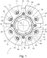
- a damping system 1 is shown with an absorber mass carrier 3, which, as in Fig. 4 illustrated, a plurality of axially spaced-apart absorber mass carrier elements 5a to 5c.
- the action principle of the absorber system 1 is illustrated with the aid of absorber mass units 8a, each having at least one absorber mass 7a, these absorber mass units 8a being like Fig. 4 further shows axially located between the two absorber mass carrier elements 5a and 5b.
- the same operating principle also applies to the absorber mass units 8b with at least one absorber mass 7b, which in Fig. 4 are provided axially between the two absorber mass carrier elements 5b and 5c.
- absorber masses 7a are in the Fig. 1 and 2 each arranged in the direction axially in front of the absorber masses 7a absorber mass carrier element 5a removed, and only the axially central absorber mass carrier element 5b shown.
- the absorber mass carrier element 5b is connected by spacers 11a to the absorber mass carrier element 5a and by spacers 11b to the absorber mass carrier element 5c.
- absorber masses 7a have each trained in pairs guideways 22 for receiving rolling bodies 20, wherein the guideways 22 are designed such that they allow a radial relative movement of the absorber masses 7a relative to the rolling bodies 20.
- the absorber masses 7a have, radially inward on their peripheral sides 42 adjacent stop sides 43.
- guideways 13 are provided, which have a curved course. As shown in Fig. 1 or 2
- the guideways 13 each have an exit region 14, in which the respective guideway 13 has the greatest radial distance from a central axis 15, and via connection regions 17 which, extending circumferentially opposite one another, adjoin both sides of the exit region 14.
- the guideways 22 provided on the absorber masses 7a, 7b also have a curved course, each having an exit region 24, in which the respective guideway 22 has the smallest radial distance from the central axis 15, and with connection regions 25 which extend circumferentially opposite each other , connect to both sides of the output area 24.
- the guideways 22 are each provided on both sides of a Tilgermassentechniks 35 of the respective absorber mass.
- the absorber masses 7a strive radially outwards, so that the rolling bodies 20 each position themselves in the output region 24 of the respective guide track 22, that is to say in that region which has the smallest radial distance from the central axis 15.
- the rolling bodies 20 are supported in each case in the exit region 14 of the absorber mass carrier elements 5a and 5b as well as 5b and 5c, ie in that region which has the greatest radial distance from the central axis 15.
- the absorber masses 7a each have at their radially inner ends in each case a geometric Anformung 28 which has a first contact portion 26 in the peripheral middle part, in the peripheral side outer parts on the other hand via second contact areas 27.
- the first contact area 26 has an area center 37, which divides the first contact region 29 into molding halves 23.
- This geometric Anformung 28 cooperates in a manner to be described below with stops 31 which are provided radially inside the absorber masses 7a and which are gripped together on an annular component 32.
- the annular member 32 has in the circumferential direction between each two absorber masses 7a via a respective holder 34, which encloses a respective spacer 11a, so that the holder 34 each serves as Anschlagaufivity 38.
- the annular member 32 is thus rotatably on the absorber mass carrier element 5b and thus received on Tilgermassenlasi 3.
- a circumferentially extending annular body 33 acts between each two Anschlagaufivity 38 each with a stop profile 40.
- Anschlagaufivity 38 and stop profiles 40 together form stops 31 on the annular member 32nd
- the absorber masses 7a strive radially outwards under the effect of the centrifugal force so that the rolling bodies 20 can respectively position themselves in the exit region 24 of the respective guide track 22 of the absorber masses 7a , Although torsional vibrations can enforce deflections of the absorber masses 7a in the circumferential direction, whereby the rolling elements 20 are deflected out of the output regions 14, 24 of the guideways 13, 22 in their connection regions 17, 25, however, with a decaying torsional vibration always a provision of the rolling elements 20 in the starting position below the effect of centrifugal force.
- the two absorber masses 7a located radially below the central axis 15 likewise fall radially inwards until their stop sides 43 with the first contact areas 26 formed thereon, which are relevant for the movement direction, abut on the associated stop profile 40 of the stop 31 on the annular body 33 of the annular component 32 have come, and until also the relevant for the direction of movement second contact portions 27 of the respective absorber masses 7a at the corresponding brackets 34 and thus at the Anschlagaufillon 38 of the annular member 32 come into abutment. In this way it is prevented that the two radially located below the central axis 15 absorber masses 7a reach with their peripheral sides 42 in abutment against each other.
- the absorber masses 7a to receive them axially between two absorber mass carrier elements 5a and 5b, and for the absorber masses 7b to receive them axially between two absorber mass carrier elements 5b and 5c. Since the axially central absorber mass carrier element 5b is thus used both to receive the absorber masses 7a and to receive the absorber masses 7b, this absorber mass carrier element 5b requires a larger number of guideways 13 than the two axially outer absorber mass carrier elements 5a and 5c on the one hand the guideways 13a for the absorber masses 7a and on the other hand the guideways 13b for the absorber masses 7b.
- Fig. 3 exemplifies the absorber mass carrier element 5a for the axially outer absorber mass carrier elements 5a and 5c.
- the guideways 13a and 13b are then formed at least substantially the same if both absorber masses 7a and 7b are to repel excitations of a drive, such as an internal combustion engine, with at least substantially the same order. If, on the other hand, suggestions with different orders are to be eradicated, then the guideways 13a and 13b differ from each other, as in FIG Fig.
- the guideways 13a are provided for eradicating 2nd order excitations
- the guideways 13b are for eradicating 1st order excitations.
- This is advantageous when the engine preceding the absorber system 1 is designed as a 4-cylinder engine in which a cylinder deactivation leads to an operation with only two cylinders. In 4-cylinder operation, the eradication of excitations of the 2nd order is to be carried out, in 2-cylinder operation, however, the eradication of excitations of the 1st order.
- the absorber masses 7a and 7b are arranged at substantially the same radii about the central axis 15 of the absorber system 1, which is why the guideways 13a and 13b are arranged with circumferential offset from one another.
- Fig. 6 A variant of this is out Fig. 6 can be removed, in which the absorber masses 7a and 7b are arranged on significantly different radii about the central axis of the absorber system 1. Understandably, in such an embodiment, the guideways for the absorber masses 7a and the guideways for the absorber masses 7b are arranged in the axially central absorber mass carrier element 5b with radial offset from one another. Otherwise no differences compared to those already in Fig. 5 Guideways 13a, 13b shown, is based on a graphic representation of the guideways in the embodiment according to Fig. 6 waived.
- the absorber system 1 is part of a torsional vibration damper 30, which is provided in the housing 54 of a hydrodynamic coupling assembly 56.
- This hydrodynamic coupling arrangement 56 has a hydrodynamic Circuit 60 with impeller 61, turbine 62 and stator 63, and a coupling device 64 which has a clutch piston 65 and a friction disc clutch 66.
- the clutch device 64 In response to the driving of the clutch piston 65, the clutch device 64 is movable between an engagement position and a disengagement position.
- the coupling device 64 is connected to a torsion damper input 67 of a damper device 70 which has two circumferential spring sets 68, 69, wherein a torsion damper intermediate component 74 is effective between the two circumferential spring sets 68, 69.
- the torsion damper output 72 of the damping device 70 cooperates with an output 73, and also serves as an absorber mass carrier element 5a.
- the absorber mass carrier element 5b is also connected to the torsion damper output 72 of the damping device 70, via an axial ejection 77 provided on the absorber mass carrier element 5b, by means of which the absorber mass carrier element 5b is provided with a guide 78 radially inwardly surrounding the radially outer circumferential spring set 69 Rivet connection is.
- This guide 78 is rotationally fixed with the torsion damper output 72 of the damping device 70.
- the damping device 70 forms together with the absorber system 1, the torsional vibration damper 30, wherein the damping device is provided axially adjacent to the absorber system 1.
- Fig. 7 is one of the in Fig. 6 illustrated embodiment deviating connection 75 to a damping device of a torsional vibration damper.
- a hub 76 is integrally formed on the damper mass carrier element 5a adjacent to a damping device in the radially inner region, which hub is provided for producing a connection to a component, not shown, of the damping device.
- the hub 76 is centered in the direction of this component of the damping device.
- the hub 76 but also according to Fig. 7b at the axially central absorber mass carrier element 5b or according to Fig. 7c be formed on the absorber mass means farthest from the said damping device 5c.
- the padding of the hub 76 in the axial direction is significantly stronger than in the former case.
- the hub 76 passes through a radially inner recess 80 in the absorber mass carrier element 5a
- the hub 76 has both a radially inner recess 81 in the absorber mass carrier element 5b as well as the radially inner recess 80 in the absorber mass carrier element 5a passes through.
Landscapes
- Engineering & Computer Science (AREA)
- General Engineering & Computer Science (AREA)
- Physics & Mathematics (AREA)
- Acoustics & Sound (AREA)
- Aviation & Aerospace Engineering (AREA)
- Mechanical Engineering (AREA)
- Mechanical Operated Clutches (AREA)
Claims (10)
- Système d'amortissement (1), présentant un support de masselotte (3) avec une pluralité d'éléments de support de masselotte (5a à 5c) disposés de manière adjacente axialement les uns aux autres, qui sont prévus pour recevoir des unités de masselotte (8a, 8b) également disposées de manière adjacente les unes aux autres, caractérisé en ce qu'au moins un élément de support de masselotte (5b) des éléments de support de masselotte (5a à 5c) est prévu pour recevoir à chaque fois deux unités de masselotte (8a, 8b) disposées de manière adjacente l'une à l'autre, avec, par rapport aux éléments de support de masselotte (5a, 5c) qui ne reçoivent à chaque fois qu'au moins une unité de masselotte (8a, 8b), dans chaque cas le double du nombre de pistes de guidage (13a, 13b), à savoir d'une part les pistes de guidage (13a) pour l'au moins une unité de masselotte (8a) d'un côté et d'autre part les pistes de guidage (13b) pour l'au moins une unité de masselotte (8b) du côté opposé.
- Système d'amortissement selon la revendication 1, caractérisé en ce qu'à chaque fois deux éléments de support de masselotte disposés à distance axiale l'un de l'autre (5a et 5b ; 5b et 5c) reçoivent axialement entre eux à chaque fois une unité de masselotte (8a, 8b) et au moins un élément de support de masselotte (5b) disposé axialement entre deux unités de masselotte (8a, 8b) à chaque fois adjacentes l'une à l'autre est prévu pour recevoir deux unités de masselotte (8a, 8b) .
- Système d'amortissement selon la revendication 1, caractérisé en ce que lors de la conception des deux unités de masselotte adjacentes l'une à l'autre (8a, 8b) en réponse à des excitations d'un entraînement, tel qu'un moteur à combustion interne, ayant des ordres différents, au niveau de l'au moins un élément de support de masselotte (5b) disposé axialement entre deux unités de masselotte adjacentes l'une à l'autre (8a, 8b), les pistes de guidage (13a, 13b) peuvent être réalisées différemment.
- Système d'amortissement selon la revendication 1, caractérisé en ce que lors de la conception des deux unités de masselotte adjacentes l'une à l'autre (8a, 8b) en réponse à des excitations d'un entraînement, tel qu'un moteur à combustion interne, ayant des ordres au moins essentiellement identiques, au niveau de l'au moins un élément de support de masselotte (5b) disposé axialement entre deux unités de masselotte adjacentes l'une à l'autre (8a, 8b), les pistes de guidage (13a, 13b) sont réalisées de manière au moins essentiellement identique.
- Système d'amortissement selon l'une quelconque des revendications 3 ou 4, caractérisé en ce que lors de l'agencement de deux unités de masselotte adjacentes l'une à l'autre (8a, 8b) au moins essentiellement sur le même diamètre autour d'un axe central (15) au niveau de l'au moins un élément de support de masselotte (5b) disposé axialement entre les deux unités de masselotte adjacentes l'une à l'autre (8a, 8b), les pistes de guidage (13a, 13b) pour les deux unités de masselotte (8a, 8b) sont réalisées avec un décalage périphérique l'une par rapport à l'autre.
- Système d'amortissement selon l'une quelconque des revendications 3 ou 4, caractérisé en ce que lors de l'agencement de deux unités de masselotte adjacentes l'une à l'autre (8a, 8b) sur des diamètres différents autour d'un axe central (15) au niveau de l'au moins un élément de support de masselotte (5b) disposé axialement entre les deux unités de masselotte adjacentes l'une à l'autre (8a, 8b), les pistes de guidage (13a, 13b) pour les deux unités de masselotte (8a, 8b) sont réalisées avec un décalage radial l'une par rapport à l'autre.
- Système d'amortissement selon la revendication 1, dans lequel l'un des éléments de support de masselotte (5a à 5c) dispose d'une liaison (75) à un dispositif d'amortissement (70) d'un amortisseur d'oscillations de torsion (30), caractérisé en ce que la liaison (75) présente un moyeu (76) prolongeant radialement à l'intérieur l'élément de support de masselotte (5a à 5c).
- Système d'amortissement selon la revendication 7, dans lequel le moyeu (62) est au moins essentiellement axialement adjacent au dispositif d'amortissement (70) de l'amortisseur d'oscillations de torsion (30), caractérisé en ce que le moyeu (76) dispose d'une composante s'étendant dans la direction du dispositif d'amortissement (70).
- Système d'amortissement selon l'une quelconque des revendications 7 ou 8, caractérisé en ce que le moyeu (76), lors de la réalisation sur un élément de support de masselotte (5b, 5c) qui est prévu du côté opposé au dispositif d'amortissement (70) de l'élément de support de masselotte (5a) adjacent à ce dispositif d'amortissement (70), vient en prise radialement à l'intérieur dans la direction axiale à travers au moins l'élément de support de masselotte (5a ; 5a et 5b) adjacent à l'amortisseur d'oscillations de torsion (30).
- Système d'amortissement selon la revendication 7, caractérisé en ce que le dispositif d'amortissement (70) de l'amortisseur d'oscillations de torsion (30), pour recevoir la liaison (75) de l'un des éléments de support de masselotte (5a à 5c), dispose d'une sortie d'amortisseur de torsion (72).
Applications Claiming Priority (1)
| Application Number | Priority Date | Filing Date | Title |
|---|---|---|---|
| DE201310219505 DE102013219505A1 (de) | 2013-09-27 | 2013-09-27 | Tilgersystem |
Publications (2)
| Publication Number | Publication Date |
|---|---|
| EP2853770A1 EP2853770A1 (fr) | 2015-04-01 |
| EP2853770B1 true EP2853770B1 (fr) | 2018-01-10 |
Family
ID=51359311
Family Applications (1)
| Application Number | Title | Priority Date | Filing Date |
|---|---|---|---|
| EP14181709.8A Not-in-force EP2853770B1 (fr) | 2013-09-27 | 2014-08-21 | Système d'absorption |
Country Status (2)
| Country | Link |
|---|---|
| EP (1) | EP2853770B1 (fr) |
| DE (1) | DE102013219505A1 (fr) |
Families Citing this family (3)
| Publication number | Priority date | Publication date | Assignee | Title |
|---|---|---|---|---|
| DE112015001593B4 (de) * | 2014-04-02 | 2025-08-14 | Schaeffler Technologies AG & Co. KG | Fliehkraftpendeleinrichtung und Drehschwingungsdämpfer |
| DE102014221639A1 (de) * | 2014-10-24 | 2016-04-28 | Zf Friedrichshafen Ag | Tilgerschwingungsdämpfer und Antriebsstrang |
| DE102015208397A1 (de) * | 2015-05-06 | 2016-11-10 | Zf Friedrichshafen Ag | Tilgeranordnung |
Family Cites Families (9)
| Publication number | Priority date | Publication date | Assignee | Title |
|---|---|---|---|---|
| DE112011100547B4 (de) | 2010-02-16 | 2021-01-14 | Schaeffler Technologies AG & Co. KG | Drehmomentübertragungseinrichtung |
| DE102011085905A1 (de) * | 2010-12-02 | 2012-06-06 | Schaeffler Technologies Gmbh & Co. Kg | Drehschwingungstilgervorrichtung und Drehmomentübertragungsvorrichtung für ein Kraftfahrzeug |
| DE102012204186A1 (de) * | 2011-03-31 | 2012-10-04 | Schaeffler Technologies AG & Co. KG | Fliehkraftpendeleinrichtung |
| DE102011076790B4 (de) | 2011-05-31 | 2023-07-13 | Zf Friedrichshafen Ag | Antriebssystem für ein Fahrzeug |
| FR2976331B1 (fr) * | 2011-06-07 | 2013-05-24 | Valeo Embrayages | Dispositif d'amortissement de torsion, notamment pour une transmission de vehicule automobile |
| EP2786042B1 (fr) * | 2011-11-28 | 2018-05-30 | Schaeffler Technologies AG & Co. KG | Pendule à force centrifuge |
| EP2600030A3 (fr) * | 2011-12-01 | 2018-01-03 | Schaeffler Technologies AG & Co. KG | Convertisseur de couple |
| DE102012212970A1 (de) * | 2012-02-28 | 2013-08-29 | Schaeffler Technologies AG & Co. KG | Drehmomentübertragungseinrichtung und Antriebsstrang mit Drehmomentübertragungseinrichtung |
| DE102012213015A1 (de) * | 2012-07-25 | 2014-02-13 | Zf Friedrichshafen Ag | Anfahrelement mit Torsionsschwingungsdämpfer und Schwingungstilger |
-
2013
- 2013-09-27 DE DE201310219505 patent/DE102013219505A1/de not_active Withdrawn
-
2014
- 2014-08-21 EP EP14181709.8A patent/EP2853770B1/fr not_active Not-in-force
Non-Patent Citations (1)
| Title |
|---|
| None * |
Also Published As
| Publication number | Publication date |
|---|---|
| EP2853770A1 (fr) | 2015-04-01 |
| DE102013219505A1 (de) | 2015-04-16 |
Similar Documents
| Publication | Publication Date | Title |
|---|---|---|
| EP2912341B1 (fr) | Amortisseur d'oscillations de torsion | |
| EP2912340B2 (fr) | Amortisseur de vibrations de torsion | |
| EP2853773B2 (fr) | Amortisseur d'oscillations de torsion | |
| EP2853772B1 (fr) | Amortisseur d'oscillations de torsion | |
| EP3377784A1 (fr) | Ensemble d'amortissement pour au moins une masse d'amortissement | |
| DE102014207258A1 (de) | Torsionsschwingungsdämpfer mit einer Dämpfungseinrichtung, einem Tilgersystem und einer Masseeinrichtung | |
| DE102019106343A1 (de) | Fliehkraftpendeleinrichtung mit einer an einen Randabschnitt herangeführten Kulissenbahn und Verfahren zur Herstellung einer Fliehkraftpendeleinrichtung | |
| EP2853770B1 (fr) | Système d'absorption | |
| WO2015067423A1 (fr) | Système d'amortisseur | |
| DE102016217217A1 (de) | Drehmomentübertragungseinrichtung | |
| EP2598774B1 (fr) | Amortisseur d'oscillations de torsion | |
| DE102016217542A1 (de) | Drehmomentübertragungseinrichtung | |
| EP2853771B1 (fr) | Amortisseur d'oscillations de torsion | |
| DE102016123987A1 (de) | Torsionsdämpfersystem | |
| DE102014208569A1 (de) | Drehschwingungsdämpfer | |
| WO2015067424A1 (fr) | Système d'amortisseur | |
| DE102014220901A1 (de) | Baueinheit einer Kopplungsanordnung mit einer Schwingungsreduzierungseinrichtung und mit einer Kupplungseinrichtung | |
| DE102014207260A1 (de) | Torsionsschwingungsdämpfer mit einer Dämpfungseinrichtung, einem Tilgersystem und einer Masseeinrichtung | |
| WO2017036473A1 (fr) | Élément de roulement pour dispositif à pendules centrifuges | |
| DE102016209972A1 (de) | Fliehkraftpendeleinrichtung mit versteiften Trägerplatten und Kupplung | |
| DE102016206500A1 (de) | Tilgersystem | |
| DE102014207257A1 (de) | Torsionsschwingungsdämpfer mit einer Dämpfungseinrichtung, einem Tilgersystem und einer Masseeinrichtung | |
| DE102011003503B4 (de) | Torsionsschwingungsdämpfer, insbesondere für einen hydrodynamischen Drehmomentwandler | |
| EP3593007B1 (fr) | Système d'amortissement | |
| WO2023025840A1 (fr) | Amortisseur de vibrations torsionnelles et procédé associé de production |
Legal Events
| Date | Code | Title | Description |
|---|---|---|---|
| PUAI | Public reference made under article 153(3) epc to a published international application that has entered the european phase |
Free format text: ORIGINAL CODE: 0009012 |
|
| 17P | Request for examination filed |
Effective date: 20140821 |
|
| AK | Designated contracting states |
Kind code of ref document: A1 Designated state(s): AL AT BE BG CH CY CZ DE DK EE ES FI FR GB GR HR HU IE IS IT LI LT LU LV MC MK MT NL NO PL PT RO RS SE SI SK SM TR |
|
| AX | Request for extension of the european patent |
Extension state: BA ME |
|
| R17P | Request for examination filed (corrected) |
Effective date: 20150630 |
|
| 17Q | First examination report despatched |
Effective date: 20161213 |
|
| GRAP | Despatch of communication of intention to grant a patent |
Free format text: ORIGINAL CODE: EPIDOSNIGR1 |
|
| INTG | Intention to grant announced |
Effective date: 20170825 |
|
| GRAS | Grant fee paid |
Free format text: ORIGINAL CODE: EPIDOSNIGR3 |
|
| GRAA | (expected) grant |
Free format text: ORIGINAL CODE: 0009210 |
|
| AK | Designated contracting states |
Kind code of ref document: B1 Designated state(s): AL AT BE BG CH CY CZ DE DK EE ES FI FR GB GR HR HU IE IS IT LI LT LU LV MC MK MT NL NO PL PT RO RS SE SI SK SM TR |
|
| REG | Reference to a national code |
Ref country code: CH Ref legal event code: EP Ref country code: AT Ref legal event code: REF Ref document number: 962762 Country of ref document: AT Kind code of ref document: T Effective date: 20180115 |
|
| REG | Reference to a national code |
Ref country code: IE Ref legal event code: FG4D Free format text: LANGUAGE OF EP DOCUMENT: GERMAN |
|
| REG | Reference to a national code |
Ref country code: DE Ref legal event code: R096 Ref document number: 502014006871 Country of ref document: DE |
|
| REG | Reference to a national code |
Ref country code: NL Ref legal event code: MP Effective date: 20180110 |
|
| PG25 | Lapsed in a contracting state [announced via postgrant information from national office to epo] |
Ref country code: NL Free format text: LAPSE BECAUSE OF FAILURE TO SUBMIT A TRANSLATION OF THE DESCRIPTION OR TO PAY THE FEE WITHIN THE PRESCRIBED TIME-LIMIT Effective date: 20180110 |
|
| REG | Reference to a national code |
Ref country code: FR Ref legal event code: PLFP Year of fee payment: 5 |
|
| PG25 | Lapsed in a contracting state [announced via postgrant information from national office to epo] |
Ref country code: ES Free format text: LAPSE BECAUSE OF FAILURE TO SUBMIT A TRANSLATION OF THE DESCRIPTION OR TO PAY THE FEE WITHIN THE PRESCRIBED TIME-LIMIT Effective date: 20180110 Ref country code: LT Free format text: LAPSE BECAUSE OF FAILURE TO SUBMIT A TRANSLATION OF THE DESCRIPTION OR TO PAY THE FEE WITHIN THE PRESCRIBED TIME-LIMIT Effective date: 20180110 Ref country code: CY Free format text: LAPSE BECAUSE OF FAILURE TO SUBMIT A TRANSLATION OF THE DESCRIPTION OR TO PAY THE FEE WITHIN THE PRESCRIBED TIME-LIMIT Effective date: 20180110 Ref country code: FI Free format text: LAPSE BECAUSE OF FAILURE TO SUBMIT A TRANSLATION OF THE DESCRIPTION OR TO PAY THE FEE WITHIN THE PRESCRIBED TIME-LIMIT Effective date: 20180110 Ref country code: NO Free format text: LAPSE BECAUSE OF FAILURE TO SUBMIT A TRANSLATION OF THE DESCRIPTION OR TO PAY THE FEE WITHIN THE PRESCRIBED TIME-LIMIT Effective date: 20180410 Ref country code: HR Free format text: LAPSE BECAUSE OF FAILURE TO SUBMIT A TRANSLATION OF THE DESCRIPTION OR TO PAY THE FEE WITHIN THE PRESCRIBED TIME-LIMIT Effective date: 20180110 |
|
| PG25 | Lapsed in a contracting state [announced via postgrant information from national office to epo] |
Ref country code: BG Free format text: LAPSE BECAUSE OF FAILURE TO SUBMIT A TRANSLATION OF THE DESCRIPTION OR TO PAY THE FEE WITHIN THE PRESCRIBED TIME-LIMIT Effective date: 20180410 Ref country code: PL Free format text: LAPSE BECAUSE OF FAILURE TO SUBMIT A TRANSLATION OF THE DESCRIPTION OR TO PAY THE FEE WITHIN THE PRESCRIBED TIME-LIMIT Effective date: 20180110 Ref country code: GR Free format text: LAPSE BECAUSE OF FAILURE TO SUBMIT A TRANSLATION OF THE DESCRIPTION OR TO PAY THE FEE WITHIN THE PRESCRIBED TIME-LIMIT Effective date: 20180411 Ref country code: IS Free format text: LAPSE BECAUSE OF FAILURE TO SUBMIT A TRANSLATION OF THE DESCRIPTION OR TO PAY THE FEE WITHIN THE PRESCRIBED TIME-LIMIT Effective date: 20180510 Ref country code: SE Free format text: LAPSE BECAUSE OF FAILURE TO SUBMIT A TRANSLATION OF THE DESCRIPTION OR TO PAY THE FEE WITHIN THE PRESCRIBED TIME-LIMIT Effective date: 20180110 Ref country code: LV Free format text: LAPSE BECAUSE OF FAILURE TO SUBMIT A TRANSLATION OF THE DESCRIPTION OR TO PAY THE FEE WITHIN THE PRESCRIBED TIME-LIMIT Effective date: 20180110 Ref country code: RS Free format text: LAPSE BECAUSE OF FAILURE TO SUBMIT A TRANSLATION OF THE DESCRIPTION OR TO PAY THE FEE WITHIN THE PRESCRIBED TIME-LIMIT Effective date: 20180110 |
|
| PG25 | Lapsed in a contracting state [announced via postgrant information from national office to epo] |
Ref country code: MT Free format text: LAPSE BECAUSE OF FAILURE TO SUBMIT A TRANSLATION OF THE DESCRIPTION OR TO PAY THE FEE WITHIN THE PRESCRIBED TIME-LIMIT Effective date: 20180110 |
|
| REG | Reference to a national code |
Ref country code: DE Ref legal event code: R097 Ref document number: 502014006871 Country of ref document: DE |
|
| PG25 | Lapsed in a contracting state [announced via postgrant information from national office to epo] |
Ref country code: RO Free format text: LAPSE BECAUSE OF FAILURE TO SUBMIT A TRANSLATION OF THE DESCRIPTION OR TO PAY THE FEE WITHIN THE PRESCRIBED TIME-LIMIT Effective date: 20180110 Ref country code: AL Free format text: LAPSE BECAUSE OF FAILURE TO SUBMIT A TRANSLATION OF THE DESCRIPTION OR TO PAY THE FEE WITHIN THE PRESCRIBED TIME-LIMIT Effective date: 20180110 Ref country code: IT Free format text: LAPSE BECAUSE OF FAILURE TO SUBMIT A TRANSLATION OF THE DESCRIPTION OR TO PAY THE FEE WITHIN THE PRESCRIBED TIME-LIMIT Effective date: 20180110 Ref country code: EE Free format text: LAPSE BECAUSE OF FAILURE TO SUBMIT A TRANSLATION OF THE DESCRIPTION OR TO PAY THE FEE WITHIN THE PRESCRIBED TIME-LIMIT Effective date: 20180110 |
|
| PLBE | No opposition filed within time limit |
Free format text: ORIGINAL CODE: 0009261 |
|
| STAA | Information on the status of an ep patent application or granted ep patent |
Free format text: STATUS: NO OPPOSITION FILED WITHIN TIME LIMIT |
|
| PG25 | Lapsed in a contracting state [announced via postgrant information from national office to epo] |
Ref country code: DK Free format text: LAPSE BECAUSE OF FAILURE TO SUBMIT A TRANSLATION OF THE DESCRIPTION OR TO PAY THE FEE WITHIN THE PRESCRIBED TIME-LIMIT Effective date: 20180110 Ref country code: SM Free format text: LAPSE BECAUSE OF FAILURE TO SUBMIT A TRANSLATION OF THE DESCRIPTION OR TO PAY THE FEE WITHIN THE PRESCRIBED TIME-LIMIT Effective date: 20180110 Ref country code: CZ Free format text: LAPSE BECAUSE OF FAILURE TO SUBMIT A TRANSLATION OF THE DESCRIPTION OR TO PAY THE FEE WITHIN THE PRESCRIBED TIME-LIMIT Effective date: 20180110 Ref country code: SK Free format text: LAPSE BECAUSE OF FAILURE TO SUBMIT A TRANSLATION OF THE DESCRIPTION OR TO PAY THE FEE WITHIN THE PRESCRIBED TIME-LIMIT Effective date: 20180110 |
|
| 26N | No opposition filed |
Effective date: 20181011 |
|
| PG25 | Lapsed in a contracting state [announced via postgrant information from national office to epo] |
Ref country code: SI Free format text: LAPSE BECAUSE OF FAILURE TO SUBMIT A TRANSLATION OF THE DESCRIPTION OR TO PAY THE FEE WITHIN THE PRESCRIBED TIME-LIMIT Effective date: 20180110 |
|
| PG25 | Lapsed in a contracting state [announced via postgrant information from national office to epo] |
Ref country code: MC Free format text: LAPSE BECAUSE OF FAILURE TO SUBMIT A TRANSLATION OF THE DESCRIPTION OR TO PAY THE FEE WITHIN THE PRESCRIBED TIME-LIMIT Effective date: 20180110 |
|
| REG | Reference to a national code |
Ref country code: CH Ref legal event code: PL |
|
| GBPC | Gb: european patent ceased through non-payment of renewal fee |
Effective date: 20180821 |
|
| PG25 | Lapsed in a contracting state [announced via postgrant information from national office to epo] |
Ref country code: LI Free format text: LAPSE BECAUSE OF NON-PAYMENT OF DUE FEES Effective date: 20180831 Ref country code: LU Free format text: LAPSE BECAUSE OF NON-PAYMENT OF DUE FEES Effective date: 20180821 Ref country code: CH Free format text: LAPSE BECAUSE OF NON-PAYMENT OF DUE FEES Effective date: 20180831 |
|
| REG | Reference to a national code |
Ref country code: BE Ref legal event code: MM Effective date: 20180831 |
|
| PG25 | Lapsed in a contracting state [announced via postgrant information from national office to epo] |
Ref country code: BE Free format text: LAPSE BECAUSE OF NON-PAYMENT OF DUE FEES Effective date: 20180831 |
|
| PG25 | Lapsed in a contracting state [announced via postgrant information from national office to epo] |
Ref country code: GB Free format text: LAPSE BECAUSE OF NON-PAYMENT OF DUE FEES Effective date: 20180821 |
|
| PG25 | Lapsed in a contracting state [announced via postgrant information from national office to epo] |
Ref country code: TR Free format text: LAPSE BECAUSE OF FAILURE TO SUBMIT A TRANSLATION OF THE DESCRIPTION OR TO PAY THE FEE WITHIN THE PRESCRIBED TIME-LIMIT Effective date: 20180110 |
|
| PG25 | Lapsed in a contracting state [announced via postgrant information from national office to epo] |
Ref country code: PT Free format text: LAPSE BECAUSE OF FAILURE TO SUBMIT A TRANSLATION OF THE DESCRIPTION OR TO PAY THE FEE WITHIN THE PRESCRIBED TIME-LIMIT Effective date: 20180110 Ref country code: HU Free format text: LAPSE BECAUSE OF FAILURE TO SUBMIT A TRANSLATION OF THE DESCRIPTION OR TO PAY THE FEE WITHIN THE PRESCRIBED TIME-LIMIT; INVALID AB INITIO Effective date: 20140821 |
|
| PG25 | Lapsed in a contracting state [announced via postgrant information from national office to epo] |
Ref country code: MK Free format text: LAPSE BECAUSE OF NON-PAYMENT OF DUE FEES Effective date: 20180110 Ref country code: IE Free format text: LAPSE BECAUSE OF NON-PAYMENT OF DUE FEES Effective date: 20180821 |
|
| REG | Reference to a national code |
Ref country code: AT Ref legal event code: MM01 Ref document number: 962762 Country of ref document: AT Kind code of ref document: T Effective date: 20190821 |
|
| PG25 | Lapsed in a contracting state [announced via postgrant information from national office to epo] |
Ref country code: AT Free format text: LAPSE BECAUSE OF NON-PAYMENT OF DUE FEES Effective date: 20190821 |
|
| PGFP | Annual fee paid to national office [announced via postgrant information from national office to epo] |
Ref country code: DE Payment date: 20220608 Year of fee payment: 9 |
|
| PGFP | Annual fee paid to national office [announced via postgrant information from national office to epo] |
Ref country code: FR Payment date: 20220709 Year of fee payment: 9 |
|
| P01 | Opt-out of the competence of the unified patent court (upc) registered |
Effective date: 20230528 |
|
| REG | Reference to a national code |
Ref country code: DE Ref legal event code: R119 Ref document number: 502014006871 Country of ref document: DE |
|
| PG25 | Lapsed in a contracting state [announced via postgrant information from national office to epo] |
Ref country code: FR Free format text: LAPSE BECAUSE OF NON-PAYMENT OF DUE FEES Effective date: 20230831 Ref country code: DE Free format text: LAPSE BECAUSE OF NON-PAYMENT OF DUE FEES Effective date: 20240301 |