EP2853820A1 - Vorrichtung zum Garen von Lebensmitteln - Google Patents
Vorrichtung zum Garen von Lebensmitteln Download PDFInfo
- Publication number
- EP2853820A1 EP2853820A1 EP14174915.0A EP14174915A EP2853820A1 EP 2853820 A1 EP2853820 A1 EP 2853820A1 EP 14174915 A EP14174915 A EP 14174915A EP 2853820 A1 EP2853820 A1 EP 2853820A1
- Authority
- EP
- European Patent Office
- Prior art keywords
- heating plate
- plate
- heating unit
- drawer
- heating
- Prior art date
- Legal status (The legal status is an assumption and is not a legal conclusion. Google has not performed a legal analysis and makes no representation as to the accuracy of the status listed.)
- Granted
Links
Images


Classifications
-
- F—MECHANICAL ENGINEERING; LIGHTING; HEATING; WEAPONS; BLASTING
- F24—HEATING; RANGES; VENTILATING
- F24C—DOMESTIC STOVES OR RANGES ; DETAILS OF DOMESTIC STOVES OR RANGES, OF GENERAL APPLICATION
- F24C15/00—Details
- F24C15/16—Shelves, racks or trays inside ovens; Supports therefor
- F24C15/162—Co-operating with a door, e.g. operated by the door
-
- A—HUMAN NECESSITIES
- A47—FURNITURE; DOMESTIC ARTICLES OR APPLIANCES; COFFEE MILLS; SPICE MILLS; SUCTION CLEANERS IN GENERAL
- A47J—KITCHEN EQUIPMENT; COFFEE MILLS; SPICE MILLS; APPARATUS FOR MAKING BEVERAGES
- A47J37/00—Baking; Roasting; Grilling; Frying
- A47J37/06—Roasters; Grills; Sandwich grills
- A47J37/0623—Small-size cooking ovens, i.e. defining an at least partially closed cooking cavity
- A47J37/0629—Small-size cooking ovens, i.e. defining an at least partially closed cooking cavity with electric heating elements
-
- H—ELECTRICITY
- H05—ELECTRIC TECHNIQUES NOT OTHERWISE PROVIDED FOR
- H05B—ELECTRIC HEATING; ELECTRIC LIGHT SOURCES NOT OTHERWISE PROVIDED FOR; CIRCUIT ARRANGEMENTS FOR ELECTRIC LIGHT SOURCES, IN GENERAL
- H05B6/00—Heating by electric, magnetic or electromagnetic fields
- H05B6/02—Induction heating
- H05B6/10—Induction heating apparatus, other than furnaces, for specific applications
- H05B6/12—Cooking devices
- H05B6/129—Cooking devices induction ovens
Definitions
- the invention relates to a device for cooking food, comprising an upper and a lower heating plate.
- the invention further relates to a kitchen furniture with a receptacle and a device arranged therein, device for cooking food.
- the object of the invention is to propose an improved device of the type specified.
- the heating behavior and the possibility of cleaning the device in the kitchen furniture to be improved.
- the invention relates to a device for cooking food.
- the device comprises a housing and an upper and a lower heating plate. At least one and preferably the upper heating plate is mounted in the housing so that it can be moved from a first position to a second position. In the first position, the two heating plates are arranged parallel to each other. In the second position, the vertical distance of Heating plates is at least partially larger than in the first position.
- a heater and preferably an induction heater is arranged, which together with the associated heating plate forms an upper or lower heating unit or a part thereof.
- one and preferably the upper heating plate is mounted in the receptacle so that it can be moved away from the other heating plate.
- the distance of the bearing surfaces or cooking surfaces of the heating plates increases at least in sections, and preferably everywhere.
- the surfaces of the heating plates may be at an angle to each other.
- Cooking is understood to mean roasting, toasting and / or grilling of the foodstuffs located in the device.
- the food is sandwiched between the upper and lower heating plates.
- the upper heating plate touches foods of different thickness. This can be achieved by a vertically flexible, for example, vertically guided and / or sprung storage of one and preferably the upper heating plate.
- the heating plates are heated by this heater. Behind the respective heating plate means above the upper heating plate and below the lower heating plate behind the rear surface facing the support surface.
- the heating unit is optionally mounted as a whole in the receptacle so that it can be moved from a first position to a second position. This is especially true for the upper heating unit.
- the heating unit also comprises further components, such as at least one carrier for holding the heating plate and the heater.
- the carrier may be made of metal or a heat-resistant plastic, for example.
- the induction heating is preferably a current-carrying coil. Induction-based heating plates are among others advantageous due to its fast response and good energy yield.
- the upper and / or lower heating plate is releasably secured to the respective heating unit.
- the heating plate can therefore be reversibly removed from the respective heating unit or the carrier, for example, to clean the hot plate in the dishwasher.
- Suitable types of fastening for the releasable attachment include inter alia a locking mechanism, for example using metal springs, or a magnetic connection.
- the lower heating plate may for example also be easily inserted into a receptacle of the lower heating unit.
- an intermediate plate is arranged between the upper and / or lower heating plate and the respective heater.
- the intermediate plate has a flat surface.
- the intermediate plate covers the heater completely and tightly.
- a complete and dense covering may mean that the intermediate plate closes positively on all sides with the support of the heating unit.
- the intermediate plate may optionally be glued peripherally with the carrier. This prevents contamination of the heater and also allows easy cleaning of the heating unit with removed heating plate.
- the intermediate plate is made of a heat-resistant and electrically insulating material.
- a glass ceramic Preference is given to the use of a glass ceramic.
- Glass-ceramic plates have a high transmittance for heat radiation or the electric field of an induction heater, and have a low thermal expansion. They have a smooth and non-porous surface. The thermal conductivity is low, which means that the surrounding area is not heated too much.
- Main constituents of a preferred glass ceramic are lithium, aluminum and silicon oxide.
- the upper and / or lower heating plate comprises or consists of a metal, and preferably a ferromagnetic material such as an iron alloy. This allows or favors the inductive heating of the heating plates. Iron alloys, in particular, usually have suitable electrical resistances for inductive heating.
- a housing basically any frame is understood that is suitable to carry the heating units, etc. of the device according to the invention and to fix against each other.
- the housing is a receptacle of a kitchen cabinet.
- the receptacle comprises a drawer.
- the device according to the invention can be arranged at least partially on the drawer or form part of the drawer.
- a partial arrangement on the drawer may mean that a heating unit, for example the upper heating unit is fixed in the receptacle and is not arranged on the drawer, while the other heating unit, for example the lower heating unit is arranged on the drawer.
- the support of the lower heating unit is attached to the drawer or forms part of the drawer bottom.
- the receptacle can also accommodate a device according to the invention with a housing formed separately from the receptacle.
- At least one and preferably the upper heating unit is formed or fixed in the receptacle of the kitchen appliance such that the associated heating plate moves from the first position to the second position when the drawer is opened.
- the upper heating unit is mounted in the receptacle such that movement from the first position to the second position occurs in synchronism with the opening of the drawer. But equally asynchronous movements may be provided, for example, that the movement from the first position to the second position from a certain opening degree of the drawer suddenly occurs.
- At least one and preferably the lower heating unit is mounted in the drawer of the kitchen cabinet.
- the upper and lower heating plate can be the same size and / or be shaped equal.
- the upper and / or the lower heating plate may have a structure and preferably grooves on the contact surface or contact surface for the food.
- the invention further relates to a kitchen furniture with a receptacle and therein arranged device (3) for cooking food, wherein the recording of the kitchen furniture with the housing (1) of the device is connected or the housing (1).
- the kitchen furniture may be, for example, a built-in wardrobe or a built-in chest of drawers for a kitchen.
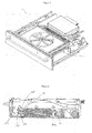
- a receptacle 1 of an embodiment of a kitchen cabinet according to the invention is shown, which has a drawer 2 and an inventive device 3 for cooking food.
- Figures 1 and 2 show this recording with closed drawer and FIGS. 3 and 4 show this recording with open drawer.
- the drawer 2 is longitudinally displaceably guided in the receptacle 1 and comprises a lower heating unit 100 of the device 3.
- This lower heating unit 100 is in FIG. 5 shown in enlarged view.
- the heating plate 101 comprises a heating plate 101, behind which an induction coil 102 is arranged.
- the heating plate 101 has a support surface 101 a for toasting bread or for grilling or the like.
- the heating plate 101 and the induction coil 102 are arranged together in the carrier 103, which forms part of the drawer.
- the carrier 104 is made of a plastic material.
- In the induction coil 102 it is a current-carrying copper wire coil.
- the heating plate 101 is detachably attached to the heating unit 100 by being inserted into a recess 104 of the carrier 103.
- the heating plate 101 can therefore be reversibly removed from the heating unit 100 for cleaning.
- an intermediate plate 105 is arranged with a smooth and non-porous surface.
- the heating plate 101 lies completely on this surface. Between the induction coil 102 and the intermediate plate 105 spacers 106 are arranged.
- the intermediate plate 105 is made of Ceran®, a glass ceramic of Schott AG, whose main components are lithium, aluminum and silicon oxide. This material has high electric field permeability of the induction coil 102 and a small thermal expansion coefficient. It also has a low thermal conductivity, so that the waste heat of the overlying heating plate 101 in the operating state of the heating unit 100 is not transmitted too much to the plastic carrier 103.
- the intermediate plate covers the induction coil 102 completely and tightly, and is peripherally bonded to the support surface 104a in the receptacle 104. This prevents contamination of the induction coil 102 and allows easy cleaning of the drawer 2 with the heating plate removed.
- the heating plate 101 is made of a ferromagnetic iron alloy, which favors inductive heating. It has on the support surface 101 a for the food on a grooved structure to give the food the desired rust structure and to reduce sticking of the food.
- an upper heating plate 11 is disposed above the lower heating plate 9.
- the upper heating plate 11 comprises a grill plate 12, which is arranged on its underside, a heat generator 13, which is designed as a radiant heater and which is disposed at the top of the upper heating plate 11, and a cover 14 for the radiant heater, which is arranged between the grill plate 12 and the heat generator 13.
- the grill plate 12 is designed as a plate with transverse recesses on its underside. It is detachably attached to the upper heating plate 11 and can be removed in particular for cleaning purposes and then reattached.
- an upper heating unit 200 which is constructed similarly to the lower heating unit 100.
- only metal springs 207 are provided on the upper heating unit 200 in order to allow a reversibly detachable fastening of the heating plate 201, but at the same time to prevent a force-induced detachment from the intermediate plate 205.
- the upper heating unit 200 is mounted in the receptacle 1 so that the upper heating plate 201 moves from a first position (shown in FIG. 2 ) to a second position (shown in FIG. 4 ) emotional.
- upper heating unit 200 is pivotally attached to a first lever 10 and to a second lever 11 on the ceiling of the receptacle 1. Both levers 10 and 11 are pivotally mounted for this purpose about an axis on the ceiling of the receptacle 1.
- the second lever 11 includes a slot 12 for receiving a journal 208 on the upper heating unit 200.
- the slot 12 is curved along a circular path, wherein the circle center is defined by the pivot axis of the second lever 11.
- the second lever 11 is pivoted by force, whereby a movement of the heating unit 200 from the first position to the second position and can be reversed.
- the force can be generated by a motor or mechanically by moving the drawer.
- the drawer 2 is initially in the withdrawn state, the in FIGS. 3 and 4 is shown.
- the upper heating unit 200 is in the raised second position.
- the food can be placed on the heating plate 101.
- the drawer 2 is inserted into the receptacle 1.
Landscapes
- Engineering & Computer Science (AREA)
- Chemical & Material Sciences (AREA)
- Combustion & Propulsion (AREA)
- Mechanical Engineering (AREA)
- General Engineering & Computer Science (AREA)
- Physics & Mathematics (AREA)
- Electromagnetism (AREA)
- Food Science & Technology (AREA)
- Baking, Grill, Roasting (AREA)
- Electric Stoves And Ranges (AREA)
- Electric Ovens (AREA)
Description
- Die Erfindung betrifft eine Vorrichtung zum Garen von Lebensmitteln, die eine obere und eine untere Heizplatte umfasst. Die Erfindung betrifft ferner ein Küchenmöbel mit einer Aufnahme und einer darin angeordneten derartigen Vorrichtung, Vorrichtung zum Garen von Lebensmitteln.
- Aus der
DE 10 2011 101 042 A1 ist ein Küchenmöbel mit einer Schublade bekannt, in der sich eine gattungsgemäße Vorrichtung befindet. - Aufgabe der Erfindung ist es, eine verbesserte Vorrichtung der eingangs angegebenen Art vorzuschlagen. Insbesondere sollen das Heizverhalten und die Möglichkeit der Reinigung der Vorrichtung im Küchenmöbel verbessert werden.
- Vor diesem Hintergrund betrifft die Erfindung eine Vorrichtung zum Garen von Lebensmitteln. Die Vorrichtung umfasst ein Gehäuse sowie eine obere und eine untere Heizplatte. Wenigstens eine und vorzugsweise die obere Heizplatte ist derart in dem Gehäuse befestigt, dass sie von einer ersten Stellung in eine zweite Stellung bewegt werden kann. In der ersten Stellung sind die beiden Heizplatten parallel zueinander angeordnet. In der zweiten Stellung ist der Vertikalabstand der Heizplatten zumindest abschnittsweise größer ist als in der ersten Stellung. Hinter der oberen und/oder der unteren Heizplatte ist eine Heizung und vorzugsweise eine Induktionsheizung angeordnet, die gemeinsam mit der dazugehörigen Heizplatte eine obere bzw. untere Heizeinheit oder einen Teil davon bildet.
- Dies bedeutet, dass eine und vorzugsweise die obere Heizplatte so in der Aufnahme befestigt ist, dass sie von der anderen Heizplatte wegbewegt werden kann. Beim Übertritt der Heizplatte von der ersten in die zweite Stellung vergrößert sich der Abstand der Auflageflächen bzw. Garflächen der Heizplatten zumindest abschnittsweise und vorzugsweise überall. In der zweiten Stellung können die Flächen der Heizplatten in einem Winkel zueinander stehen. Unter einem Garen wird ein Braten, Toasten und/oder Grillen der Lebensmittel verstanden, die sich in der Vorrichtung befinden. Die Lebensmittel werden zwischen der oberen und der unteren Heizplatte eingefasst. Bevorzugt ist dabei, dass die obere Heizplatte Lebensmittel unterschiedlicher Dicke berührt. Dies kann durch eine vertikal flexible, beispielsweise vertikal geführte und/oder gefederte Lagerung einer und vorzugsweise der oberen Heizplatte erreicht werden.
- Die Heizplatten werden durch diese Heizung beheizt. Hinter der jeweiligen Heizplatte bedeutet oberhalb der oberen Heizplatte und unterhalb der unteren Heizplatte hinter deren der Auflagefläche gegenüberstehenden Rückfläche. Die Heizeinheit ist ggf. als Ganzes so in der Aufnahme befestigt ist, dass sie von einer ersten Stellung in eine zweite Stellung bewegt werden kann. Dies gilt insbesondere für die obere Heizeinheit. Die Heizeinheit umfasst in der Regel noch weitere Bauteile wie zumindest einen Träger zur Aufnahme der Heizplatte und der Heizung. Der Träger kann beispielsweise aus Metall oder einem hitzebeständigen Kunststoff gefertigt sein. Bei der Induktionsheizung handelt es sich vorzugsweise um eine stromdurchflossene Spule. Heizplatten auf Induktionsbasis sind unter anderem aufgrund Ihres schnellen Ansprechverhaltens und der guten Energieausbeute vorteilhaft.
- In einer Ausführungsform ist die obere und/oder die untere Heizplatte lösbar an der jeweiligen Heizeinheit befestigt. Die Heizplatte kann also reversibel von der jeweiligen Heizeinheit bzw. dem Träger abgenommen werden, beispielweise um die Heizplatte in der Spülmaschine zu reinigen. Geeignete Befestigungsarten für die lösbare Befestigung umfassen unter anderem einen Rastmechanismus, beispielweise unter Verwendung von Metallfedern, oder eine Magnetverbindung. Die untere Heizplatte kann beispielsweise auch einfach in eine Aufnahme der unteren Heizeinheit eingelegt sein.
- In einer Ausführungsform ist zwischen der oberen und/oder unteren Heizplatte und der jeweiligen Heizung eine Zwischenplatte angeordnet.
- In einer Ausführungsform weist die Zwischenplatte eine ebene Oberfläche auf.
- In einer Ausführungsform überdeckt die Zwischenplatte die Heizung vollständig und dicht. Ein vollständiges und dichtes Überdecken kann bedeuten, dass die Zwischenplatte auf allen Seiten formschlüssig mit dem Träger der Heizeinheit abschließt. Die Zwischenplatte kann mit dem Träger gegebenenfalls umlaufend verklebt sein. Dies verhindert eine Verschmutzung der Heizung und ermöglicht zudem eine einfache Reinigung der Heizeinheit mit abgenommener Heizplatte.
- In einer Ausführungsform besteht die Zwischenplatte aus einem hitzebeständigen und elektrisch isolierenden Material. Bevorzugt ist dabei der Einsatz einer Glaskeramik. Platten aus Glaskeramik haben eine hohe Durchlässigkeit für Wärmestrahlung oder das elektrische Feld einer Induktionsheizung, und haben eine geringe Wärmeausdehnung. Sie besitzen eine glatte und porenfreie Oberfläche. Die Wärmeleitfähigkeit ist gering, was dazu führt, dass der umgebende Bereich nicht zu stark erhitzt wird. Hauptbestandteile einer bevorzugten Glaskeramik sind Lithium-, Aluminium- und Siliziumoxid.
- In einer Ausführungsform weist die obere und/oder die untere Heizplatte ein Metall und vorzugsweise ein ferromagnetisches Material wie beispielsweise eine Eisenlegierung auf oder besteht daraus. Dies ermöglicht bzw. begünstigt die induktive Beheizung der Heizplatten. Insbesondere Eisenlegierungen haben in der Regel geeignete elektrische Widerstände für eine induktive Beheizung.
- Unter einem Gehäuse wird grundsätzlich jeder Rahmen verstanden, der geeignet ist, die Heizeinheiten etc. der erfindungsgemäßen Vorrichtung zu tragen und gegeneinander zu fixeren.
- In einer Ausführungsform handelt es sich bei dem Gehäuse um eine Aufnahme eines Küchenmöbels. In einer Ausführungsform umfasst die Aufnahme eine Schublade. Die erfindungsgemäße Vorrichtung kann zumindest teilweise an der Schublade angeordnet sein bzw. Bestandteil der Schublade bilden. Eine teilweise Anordnung an der Schublade kann bedeuten, dass eine Heizeinheit, beispielsweise die obere Heizeinheit in der Aufnahme befestigt ist und nicht an der Schublade angeordnet ist, während die andere Heizeinheit, beispielsweise die untere Heizeinheit an der Schublade angeordnet ist. Beispielsweise kann vorgesehen sein, dass der Träger der unteren Heizeinheit an der Schublade befestigt ist oder Teil des Schubladenbodens bildet.
- Alternativ kann die Aufnahme auch eine erfindungsgemäße Vorrichtung mit einem separat von der Aufnahme ausgebildeten Gehäuse aufnehmen.
- In einer Ausführungsform ist wenigstens eine und vorzugsweise die obere Heizeinheit so ausgebildet oder in der Aufnahme des Küchenmöbels befestigt, dass die dazugehörige Heizplatte sich beim Öffnen der Schublade von der ersten Stellung in die zweite Stellung bewegt. Dies umfasst Ausführungsformen, wobei die obere Heizeinheit so in der Aufnahme befestigt ist, dass die Bewegung von der ersten Stellung in die zweite Stellung synchron mit dem Öffnen der Schublade erfolgt. Aber gleichermaßen können auch asynchrone Bewegungen vorgesehen sein, beispielsweise dass die Bewegung von der ersten Stellung in die zweite Stellung ab einem gewissen Öffnungsgrad der Schublade plötzlich erfolgt.
- In einer Ausführungsform ist wenigstens eine und vorzugsweise die untere Heizeinheit in der Schublade des Küchenmöbels befestigt.
- Die obere und die untere Heizplatte können gleich groß sind und/oder gleich geformt sein. Die obere und/oder die untere Heizplatte können an der Kontaktfläche bzw. Auflagefläche für das Lebensmittel eine Struktur und vorzugsweise Rillen aufweisen.
- Die Erfindung betrifft ferner ein Küchenmöbel mit einer Aufnahme und einer darin angeordneten erfindungsgemäßen Vorrichtung (3) zum Garen von Lebensmitteln, wobei die Aufnahme des Küchenmöbels mit dem Gehäuse (1) der Vorrichtung verbunden ist oder das Gehäuse (1) darstellt. Bei dem Küchenmöbel kann es sich beispielsweise um einen Einbauschrank bzw. eine Einbaukommode für eine Küche handeln.
- Weitere Einzelheiten und Vorteile ergeben sich aus dem nachfolgend anhand der Figuren beschriebenen Ausführungsbeispiel. In den Figuren zeigen:
- Figur 1:
- eine Aufnahme eines erfindungsgemäßen Küchenmöbels mit darin angeordneter Schublade und erfindungsgemäßer Vorrichtung zum Garen von Lebensmitteln in perspektivischer Ansicht;
- Figur 2:
- die Aufnahme aus
Figur 1 im Querschnitt; - Figur 3:
- eine perspektivische Ansicht der Aufnahme aus
Figur 1 mit geöffneter Schublade; - Figur 4:
- die Aufnahme aus
Figur 3 im Querschnitt; und - Figur 5:
- eine vergrößerte Querschnittsansicht einer in der Vorrichtung angeordneten Heizeinheit.
- In den Figuren wird eine Aufnahme 1 einer Ausführungsform eines erfindungsgemäßen Küchenmöbels dargestellt, die eine Schublade 2 und eine erfindungsgemäße Vorrichtung 3 zum Garen von Lebensmitteln aufweist.
Figuren 1 und 2 zeigen diese Aufnahme mit geschlossener Schublade undFiguren 3 und 4 zeigen diese Aufnahme mit offener Schublade. - Die Schublade 2 ist in der Aufnahme 1 längsverschiebbar geführt und umfasst eine untere Heizeinheit 100 der Vorrichtung 3. Diese untere Heizeinheit 100 wird in
Figur 5 in vergrößerter Ansicht gezeigt. - Sie umfasst eine Heizplatte 101, hinter der eine Induktionsspule 102 angeordnet ist. Die Heizplatte 101 weist eine Auflagefläche 101 a zum Toasten von Brot bzw. zum Grillen oder dergleichen auf. Die Heizplatte 101 und die Induktionsspule 102 sind gemeinsam in dem Träger 103 angeordnet, der Teil der Schublade bildet. Der Träger 104 ist aus einem Kunststoffmaterial gefertigt. Bei der Induktionsspule 102 handelt es sich um eine stromdurchflossene Kupferdrahtspule. Die Heizplatte 101 ist lösbar an der Heizeinheit 100 befestigt, indem sie in eine Ausnehmung 104 des Trägers 103 eingelegt ist. Die Heizplatte 101 kann also zur Reinigung reversibel von der Heizeinheit 100 abgenommen werden. Zwischen der Heizplatte 101 und der Induktionsspule 102 ist eine Zwischenplatte 105 mit einer glatten und porenfreien Oberfläche angeordnet. Die Heizplatte 101 liegt vollflächig auf dieser Oberfläche auf. Zwischen der Induktionsspule 102 und der Zwischenplatte 105 sind Abstandshalter 106 angeordnet.
- Die Zwischenplatte 105 ist aus Ceran®, einer Glaskeramik der Schott AG gefertigt, deren Hauptbestandteile Lithium-, Aluminium- und Siliziumoxid sind. Dieses Material hat eine hohe Durchlässigkeit für das elektrische Feld der Induktionsspule 102 und einen geringen thermischen Längenausdehnungskoeffizienten. Es weist ferner eine geringe Wärmeleitfähigkeit auf, sodass die Abwärme der aufliegenden Heizplatte 101 im Betriebszustand der Heizeinheit 100 nicht zu stark an den Kunststoffträger 103 weitergegeben wird. Die Zwischenplatte überdeckt die Induktionsspule 102 vollständig und dicht, und ist umlaufend an der Auflagefläche 104a in der Aufnahme 104 verklebt. Dies verhindert eine Verschmutzung der Induktionsspule 102 und ermöglicht eine einfache Reinigung der Schublade 2 mit abgenommener Heizplatte.
- Die Heizplatte 101 ist aus einer ferromagnetischen Eisenlegierung gefertigt, die eine induktive Beheizung begünstigt. Sie weist an der Auflagefläche 101 a für das Lebensmittel eine gerillte Struktur auf, um dem Nahrungsmittel die gewünschte Roststruktur zu geben und ein Anhaften des Lebensmittels zu verringern.
- In dem Gehäuse 1 ist oberhalb der unteren Heizplatte 9 eine obere Heizplatte 11 angeordnet. Die obere Heizplatte 11 umfasst eine Grillplatte 12, die an ihrer Unterseite angeordnet ist, einen Hitzeerzeuger 13, der als Heizstrahler ausgebildet ist und der an der Oberseite der oberen Heizplatte 11 angeordnet ist, und eine Abdeckung 14 für den Heizstrahler, die zwischen der Grillplatte 12 und dem Hitzeerzeuger 13 angeordnet ist. Die Grillplatte 12 ist als Platte mit quer verlaufenden Vertiefungen an ihrer Unterseite ausgestaltet. Sie ist an der oberen Heizplatte 11 lösbar befestigt und kann insbesondere zu Reinigungszwecken abgenommen und danach wieder angebracht werden.
- In der Aufnahme 1 ist ferner eine obere Heizeinheit 200 vorhanden, die ähnlich der unteren Heizeinheit 100 aufgebaut ist. Im Unterschied zur unteren Heizeinheit 100 sind an der oberen Heizeinheit 200 lediglich Metallfedern 207 vorgesehen, um eine reversibel lösbare Befestigung der Heizplatte 201 zu ermöglichen, aber gleichzeitig ein schwerkraftbedingtes Ablösen von der Zwischenplatte 205 zu verhindern.
- Die obere Heizeinheit 200 ist so in der Aufnahme 1 befestigt, dass die obere Heizplatte 201 sich beim Öffnen der Schublade 2 von einer ersten Stellung (gezeigt in
Figur 2 ) in eine zweite Stellung (gezeigt inFigur 4 ) bewegt. - Was den Befestigungsmechanismus der oberen Heizplatte im Detail betrifft ,so ist obere Heizeinheit 200 an einen ersten Hebel 10 und an einem zweiten Hebel 11 an der Decke der Aufnahme 1 schwenkbar befestigt. Beide Hebel 10 und 11 sind zu diesem Zweck um eine Achse schwenkbar an der Decke der Aufnahme 1 befestigt. Der zweite Hebel 11 umfasst ein Langloch 12 zu Aufnahme eines Lagerzapfens 208 an der oberen Heizeinheit 200. Das Langloch 12 verläuft gekrümmt entlang einer kreisförmigen Bahn, wobei der Kreismittelpunkt durch die Schwenkachse des zweiten Hebels 11 definiert wird.
- Der zweite Hebel 11 wird durch Krafteinwirkung geschwenkt, wodurch eine Bewegung der Heizeinheit 200 von der ersten Stellung in die zweite Stellung und umgekehrt bewirkt werden kann. Die Krafteinwirkung kann von einem Motor oder mechanisch durch Bewegung der Schublade erzeugt werden.
- Im Betrieb befindet sich die Schublade 2 zunächst im herausgezogenen Zustand, der in
Figuren 3 und 4 gezeigt ist. Dabei befindet sich die obere Heizeinheit 200 in der angehobenen zweiten Stellung. In diesem Zustand kann das Lebensmittel auf die Heizplatte 101 aufgelegt werden. Anschließend wird die Schublade 2 in die Aufnahme 1 eingeschoben. - Anschließen wird die Schublade 2 in die Aufnahme 1 eingeschoben, um den ersten Zustand zu erreichen. Dieser Zustand ist in
Figuren 1 und 2 dargestellt. Während des Einschiebens der Schublade oder nach dem Einschieben der Schublade 2 wird die obere Heizeinheit 200 unter Verwendung des oben beschriebenen Mechanismus abgesenkt, bis sich die zweite Heizplatte 201 in einem geringen Abstand über der ersten Heizplatte 101 und parallel zu dieser befindet. Je nach Dicke des Lebensmittels kann entweder durch das Langloch 12 ein starres Aufdrücken verhindert werden oder die obere Heizeinheit 200 nicht zur Gänze abgesenkt werden.
Claims (10)
- Vorrichtung (3) zum Garen von Lebensmitteln mit einem Gehäuse (1) sowie einer oberen und einer unteren Heizplatte (101, 201), wobei wenigstens eine Heizplatte, vorzugsweise die obere Heizplatte (201) so in dem Gehäuse (1) befestigt ist, dass sie von einer ersten Stellung in eine zweite Stellung bewegt werden kann, wobei die beiden Heizplatten (101, 201) in der ersten Stellung parallel zueinander angeordnet sind und wobei der Vertikalabstand der Heizplatten (101, 201) in der zweiten Stellung zumindest abschnittsweise größer ist als in der ersten Stellung, wobei hinter der oberen Heizplatte (201) und/oder der unteren Heizplatte (101) eine Heizung (102, 202) und vorzugsweise eine Induktionsheizung angeordnet ist, die gemeinsam mit der dazugehörigen Heizplatte (101, 201) eine obere bzw. untere Heizeinheit (100, 200) oder einen Teil davon bildet.
- Vorrichtung nach Anspruch 2, dadurch gekennzeichnet, dass die obere und/oder untere Heizplatte (101, 201) lösbar an der jeweiligen Heizeinheit (100, 200) befestigt ist.
- Vorrichtung nach Anspruch 2, dadurch gekennzeichnet, dass zwischen der oberen und/oder unteren Heizplatte (101, 201) und der jeweiligen Heizung (102, 202) eine Zwischenplatte (105, 205) angeordnet ist.
- Vorrichtung nach Anspruch 3, dadurch gekennzeichnet, dass die Zwischenplatte (105, 205) eine ebene Oberfläche aufweist und/oder dass die Zwischenplatte (105, 205) die Heizung (102, 202) vollständig und dicht überdeckt.
- Vorrichtung nach Anspruch 3 oder 4, dadurch gekennzeichnet, dass die Zwischenplatte (105, 205) aus einem hitzebeständigen und elektrisch isolierenden Material besteht, vorzugsweise aus einer Glaskeramik.
- Vorrichtung nach einem der vorhergehenden Ansprüche, dadurch gekennzeichnet, dass die obere und/oder die untere Heizplatte (101, 201) ein Metall und vorzugsweise ein ferromagnetisches Material wie beispielsweise eine Eisenlegierung aufweisen oder daraus bestehen.
- Vorrichtung nach einem der vorhergehenden Ansprüche, dadurch gekennzeichnet, dass es sich bei dem Gehäuse (1) um die Aufnahme eines Küchenmöbels, vorzugsweise umfassend eine Schublade (2).
- Vorrichtung nach Anspruch 7, dadurch gekennzeichnet, dass wenigstens eine Heizeinheit, vorzugsweise die obere Heizeinheit (200) konfiguriert ist bzw. so in der Aufnahme befestigt ist, dass die dazugehörige Heizplatte (101, 201) sich beim oder nach dem Öffnen der Schublade (2) von der ersten Stellung in die zweite Stellung bewegt.
- Vorrichtung nach Anspruch 7 oder 8, dadurch gekennzeichnet, dass wenigstens eine Heizeinheit, vorzugsweise die untere Heizeinheit (100) in der Schublade (2) befestigt ist.
- Küchenmöbel mit einer Aufnahme und einer darin angeordneten Vorrichtung (3) zum Garen von Lebensmitteln, wobei die Aufnahme des Küchenmöbels mit dem Gehäuse (1) der Vorrichtung verbunden ist oder das Gehäuse (1) darstellt,
dadurch gekennzeichnet,
dass die Vorrichtung (3) nach einem der vorgehenden Ansprüche ausgebildet ist.
Priority Applications (1)
| Application Number | Priority Date | Filing Date | Title |
|---|---|---|---|
| PL14174915T PL2853820T3 (pl) | 2013-09-04 | 2014-06-30 | Urządzenie do obróbki termicznej środków spożywczych |
Applications Claiming Priority (1)
| Application Number | Priority Date | Filing Date | Title |
|---|---|---|---|
| DE102013014719.0A DE102013014719A1 (de) | 2013-09-04 | 2013-09-04 | Vorrichtung zum Garen von Lebensmitteln |
Publications (2)
| Publication Number | Publication Date |
|---|---|
| EP2853820A1 true EP2853820A1 (de) | 2015-04-01 |
| EP2853820B1 EP2853820B1 (de) | 2017-11-29 |
Family
ID=51176913
Family Applications (1)
| Application Number | Title | Priority Date | Filing Date |
|---|---|---|---|
| EP14174915.0A Active EP2853820B1 (de) | 2013-09-04 | 2014-06-30 | Vorrichtung zum Garen von Lebensmitteln |
Country Status (5)
| Country | Link |
|---|---|
| EP (1) | EP2853820B1 (de) |
| DE (1) | DE102013014719A1 (de) |
| ES (1) | ES2660881T3 (de) |
| PL (1) | PL2853820T3 (de) |
| TR (1) | TR201802618T4 (de) |
Cited By (3)
| Publication number | Priority date | Publication date | Assignee | Title |
|---|---|---|---|---|
| EP2746670A3 (de) * | 2012-12-20 | 2017-06-07 | Gronbach Forschungs- und Entwicklungs GmbH & Co. KG | Gargerät |
| EP4054291A1 (de) * | 2021-03-03 | 2022-09-07 | Miele & Cie. KG | Gargerät |
| WO2023247181A1 (de) | 2022-06-21 | 2023-12-28 | BSH Hausgeräte GmbH | Dampfgarschublade mit raumteiler und heizelementen |
Families Citing this family (2)
| Publication number | Priority date | Publication date | Assignee | Title |
|---|---|---|---|---|
| DE102021105039A1 (de) | 2021-03-03 | 2022-09-08 | Miele & Cie. Kg | Einbaugargerät |
| BE1029169B1 (de) * | 2021-03-03 | 2022-10-03 | Miele & Cie | Gargerät, vorzugsweise Einbaugargerät |
Citations (5)
| Publication number | Priority date | Publication date | Assignee | Title |
|---|---|---|---|---|
| DE10001330A1 (de) * | 2000-01-14 | 2001-07-19 | Heinrich Schuermann | Elektrokochplatte |
| US20080099471A1 (en) * | 2006-10-17 | 2008-05-01 | Marino Fadelli | Apparatus for cooking food products in a quick manner on both sides thereof |
| DE102010036993B3 (de) * | 2010-08-13 | 2012-02-02 | Eisfink Max Maier Gmbh & Co. Kg | Koch- oder Grillplatte |
| DE102011101042A1 (de) | 2011-05-10 | 2012-11-15 | Gronbach Forschungs- Und Entwicklungs Gmbh & Co. Kg | Gargerät |
| DE102012003970A1 (de) * | 2012-02-29 | 2013-08-29 | Gronbach Forschungs- Und Entwicklungs Gmbh & Co. Kg | Gargerät |
Family Cites Families (1)
| Publication number | Priority date | Publication date | Assignee | Title |
|---|---|---|---|---|
| EP1818620B1 (de) * | 2006-02-10 | 2011-06-15 | Filippi S.r.l. | Backofen mit einem Backwagen mit integriertem Heizelement und Grillrosten |
-
2013
- 2013-09-04 DE DE102013014719.0A patent/DE102013014719A1/de not_active Withdrawn
-
2014
- 2014-06-30 TR TR2018/02618T patent/TR201802618T4/tr unknown
- 2014-06-30 EP EP14174915.0A patent/EP2853820B1/de active Active
- 2014-06-30 ES ES14174915.0T patent/ES2660881T3/es active Active
- 2014-06-30 PL PL14174915T patent/PL2853820T3/pl unknown
Patent Citations (5)
| Publication number | Priority date | Publication date | Assignee | Title |
|---|---|---|---|---|
| DE10001330A1 (de) * | 2000-01-14 | 2001-07-19 | Heinrich Schuermann | Elektrokochplatte |
| US20080099471A1 (en) * | 2006-10-17 | 2008-05-01 | Marino Fadelli | Apparatus for cooking food products in a quick manner on both sides thereof |
| DE102010036993B3 (de) * | 2010-08-13 | 2012-02-02 | Eisfink Max Maier Gmbh & Co. Kg | Koch- oder Grillplatte |
| DE102011101042A1 (de) | 2011-05-10 | 2012-11-15 | Gronbach Forschungs- Und Entwicklungs Gmbh & Co. Kg | Gargerät |
| DE102012003970A1 (de) * | 2012-02-29 | 2013-08-29 | Gronbach Forschungs- Und Entwicklungs Gmbh & Co. Kg | Gargerät |
Cited By (4)
| Publication number | Priority date | Publication date | Assignee | Title |
|---|---|---|---|---|
| EP2746670A3 (de) * | 2012-12-20 | 2017-06-07 | Gronbach Forschungs- und Entwicklungs GmbH & Co. KG | Gargerät |
| EP4054291A1 (de) * | 2021-03-03 | 2022-09-07 | Miele & Cie. KG | Gargerät |
| EP4054290A1 (de) * | 2021-03-03 | 2022-09-07 | Miele & Cie. KG | Gargerät |
| WO2023247181A1 (de) | 2022-06-21 | 2023-12-28 | BSH Hausgeräte GmbH | Dampfgarschublade mit raumteiler und heizelementen |
Also Published As
| Publication number | Publication date |
|---|---|
| EP2853820B1 (de) | 2017-11-29 |
| ES2660881T3 (es) | 2018-03-26 |
| TR201802618T4 (tr) | 2018-03-21 |
| PL2853820T3 (pl) | 2018-04-30 |
| DE102013014719A1 (de) | 2015-03-05 |
Similar Documents
| Publication | Publication Date | Title |
|---|---|---|
| EP2853820B1 (de) | Vorrichtung zum Garen von Lebensmitteln | |
| DE2809884A1 (de) | Kochgeraet | |
| EP2268101A1 (de) | Tiegelboden, Gargerät damit und Verfahren zum Betreiben solch eines Gargeräts | |
| DE202006012631U1 (de) | Grillvorrichtung zum Braten und/oder Garen von Speisen | |
| EP3616578B1 (de) | Elektrischer grill mit zwei einen grillraum aufspannenden grillplatten | |
| DE102009029464B4 (de) | Garraumvorrichtung mit CNT-Heizelement | |
| EP2746670B1 (de) | Gargerät | |
| DE8508617U1 (de) | Einschiebbarer oder einlegbarer Backboden für einen Backofen | |
| DE60004581T2 (de) | Herausnehmbare Heizbaugruppe für Elektroherd | |
| DE102007004275A1 (de) | Vorrichtung zur Wandlung induktiv übertragener elektrischer Energie und Verfahren zur Herstellung einer derartigen Vorrichtung | |
| EP3449786B1 (de) | Elektrisches tischraclettegerät | |
| EP2196113A2 (de) | Garkessel für die Zubereitung von Speisen | |
| DE102011055931A1 (de) | Heizelement | |
| DE102009026111A1 (de) | Kochgerät und insbesondere dafür vorgessehener gelochter GN-Behälter | |
| EP1880635A1 (de) | Speisentransportwagen | |
| DE102009019765A1 (de) | Grillvorrichtung für ein Induktionskochfeld | |
| EP2025267B1 (de) | Brühkammer aus Karbon | |
| EP3210508B1 (de) | Elektrischer grill | |
| DE4000536C2 (de) | ||
| DE202016105795U1 (de) | Vorrichtung zum form- und kraftschlüssigen Halten von Scheiben einer Einrichtung zur Wärmebehandlung von Lebensmitteln, insbesondere eines Backofens | |
| EP0697567B1 (de) | Kombinationseinrichtung zum Zubereiten warmer Speisen | |
| DE102005030493B4 (de) | System, bestehend aus mindestens einem elektrischen Küchengerät und einer Küchenarbeitsplatte | |
| DE202016003176U1 (de) | Grillschutz | |
| DE102006046427A1 (de) | Kochfeld für Speisenbehälter | |
| DE202016103127U1 (de) | Vorrichtung zum Hochtemperaturgrillen |
Legal Events
| Date | Code | Title | Description |
|---|---|---|---|
| PUAI | Public reference made under article 153(3) epc to a published international application that has entered the european phase |
Free format text: ORIGINAL CODE: 0009012 |
|
| 17P | Request for examination filed |
Effective date: 20140630 |
|
| AK | Designated contracting states |
Kind code of ref document: A1 Designated state(s): AL AT BE BG CH CY CZ DE DK EE ES FI FR GB GR HR HU IE IS IT LI LT LU LV MC MK MT NL NO PL PT RO RS SE SI SK SM TR |
|
| AX | Request for extension of the european patent |
Extension state: BA ME |
|
| REG | Reference to a national code |
Ref country code: DE Ref legal event code: R079 Ref document number: 502014006377 Country of ref document: DE Free format text: PREVIOUS MAIN CLASS: F24C0015000000 Ipc: F24C0015160000 |
|
| RIC1 | Information provided on ipc code assigned before grant |
Ipc: F24C 15/16 20060101AFI20161103BHEP Ipc: A47J 37/06 20060101ALI20161103BHEP |
|
| 17Q | First examination report despatched |
Effective date: 20161201 |
|
| GRAP | Despatch of communication of intention to grant a patent |
Free format text: ORIGINAL CODE: EPIDOSNIGR1 |
|
| INTG | Intention to grant announced |
Effective date: 20170720 |
|
| GRAS | Grant fee paid |
Free format text: ORIGINAL CODE: EPIDOSNIGR3 |
|
| GRAA | (expected) grant |
Free format text: ORIGINAL CODE: 0009210 |
|
| AK | Designated contracting states |
Kind code of ref document: B1 Designated state(s): AL AT BE BG CH CY CZ DE DK EE ES FI FR GB GR HR HU IE IS IT LI LT LU LV MC MK MT NL NO PL PT RO RS SE SI SK SM TR |
|
| REG | Reference to a national code |
Ref country code: CH Ref legal event code: EP |
|
| REG | Reference to a national code |
Ref country code: AT Ref legal event code: REF Ref document number: 950738 Country of ref document: AT Kind code of ref document: T Effective date: 20171215 |
|
| REG | Reference to a national code |
Ref country code: IE Ref legal event code: FG4D Free format text: LANGUAGE OF EP DOCUMENT: GERMAN |
|
| REG | Reference to a national code |
Ref country code: DE Ref legal event code: R096 Ref document number: 502014006377 Country of ref document: DE |
|
| REG | Reference to a national code |
Ref country code: CH Ref legal event code: NV Representative=s name: KELLER AND PARTNER PATENTANWAELTE AG, CH |
|
| REG | Reference to a national code |
Ref country code: NL Ref legal event code: FP |
|
| REG | Reference to a national code |
Ref country code: ES Ref legal event code: FG2A Ref document number: 2660881 Country of ref document: ES Kind code of ref document: T3 Effective date: 20180326 |
|
| REG | Reference to a national code |
Ref country code: LT Ref legal event code: MG4D |
|
| PG25 | Lapsed in a contracting state [announced via postgrant information from national office to epo] |
Ref country code: LT Free format text: LAPSE BECAUSE OF FAILURE TO SUBMIT A TRANSLATION OF THE DESCRIPTION OR TO PAY THE FEE WITHIN THE PRESCRIBED TIME-LIMIT Effective date: 20171129 Ref country code: SE Free format text: LAPSE BECAUSE OF FAILURE TO SUBMIT A TRANSLATION OF THE DESCRIPTION OR TO PAY THE FEE WITHIN THE PRESCRIBED TIME-LIMIT Effective date: 20171129 Ref country code: FI Free format text: LAPSE BECAUSE OF FAILURE TO SUBMIT A TRANSLATION OF THE DESCRIPTION OR TO PAY THE FEE WITHIN THE PRESCRIBED TIME-LIMIT Effective date: 20171129 Ref country code: NO Free format text: LAPSE BECAUSE OF FAILURE TO SUBMIT A TRANSLATION OF THE DESCRIPTION OR TO PAY THE FEE WITHIN THE PRESCRIBED TIME-LIMIT Effective date: 20180228 |
|
| PG25 | Lapsed in a contracting state [announced via postgrant information from national office to epo] |
Ref country code: RS Free format text: LAPSE BECAUSE OF FAILURE TO SUBMIT A TRANSLATION OF THE DESCRIPTION OR TO PAY THE FEE WITHIN THE PRESCRIBED TIME-LIMIT Effective date: 20171129 Ref country code: GR Free format text: LAPSE BECAUSE OF FAILURE TO SUBMIT A TRANSLATION OF THE DESCRIPTION OR TO PAY THE FEE WITHIN THE PRESCRIBED TIME-LIMIT Effective date: 20180301 Ref country code: HR Free format text: LAPSE BECAUSE OF FAILURE TO SUBMIT A TRANSLATION OF THE DESCRIPTION OR TO PAY THE FEE WITHIN THE PRESCRIBED TIME-LIMIT Effective date: 20171129 Ref country code: BG Free format text: LAPSE BECAUSE OF FAILURE TO SUBMIT A TRANSLATION OF THE DESCRIPTION OR TO PAY THE FEE WITHIN THE PRESCRIBED TIME-LIMIT Effective date: 20180228 Ref country code: LV Free format text: LAPSE BECAUSE OF FAILURE TO SUBMIT A TRANSLATION OF THE DESCRIPTION OR TO PAY THE FEE WITHIN THE PRESCRIBED TIME-LIMIT Effective date: 20171129 |
|
| REG | Reference to a national code |
Ref country code: FR Ref legal event code: PLFP Year of fee payment: 5 |
|
| PG25 | Lapsed in a contracting state [announced via postgrant information from national office to epo] |
Ref country code: DK Free format text: LAPSE BECAUSE OF FAILURE TO SUBMIT A TRANSLATION OF THE DESCRIPTION OR TO PAY THE FEE WITHIN THE PRESCRIBED TIME-LIMIT Effective date: 20171129 Ref country code: CZ Free format text: LAPSE BECAUSE OF FAILURE TO SUBMIT A TRANSLATION OF THE DESCRIPTION OR TO PAY THE FEE WITHIN THE PRESCRIBED TIME-LIMIT Effective date: 20171129 Ref country code: EE Free format text: LAPSE BECAUSE OF FAILURE TO SUBMIT A TRANSLATION OF THE DESCRIPTION OR TO PAY THE FEE WITHIN THE PRESCRIBED TIME-LIMIT Effective date: 20171129 Ref country code: CY Free format text: LAPSE BECAUSE OF FAILURE TO SUBMIT A TRANSLATION OF THE DESCRIPTION OR TO PAY THE FEE WITHIN THE PRESCRIBED TIME-LIMIT Effective date: 20171129 |
|
| REG | Reference to a national code |
Ref country code: DE Ref legal event code: R097 Ref document number: 502014006377 Country of ref document: DE |
|
| PG25 | Lapsed in a contracting state [announced via postgrant information from national office to epo] |
Ref country code: SM Free format text: LAPSE BECAUSE OF FAILURE TO SUBMIT A TRANSLATION OF THE DESCRIPTION OR TO PAY THE FEE WITHIN THE PRESCRIBED TIME-LIMIT Effective date: 20171129 |
|
| PG25 | Lapsed in a contracting state [announced via postgrant information from national office to epo] |
Ref country code: MT Free format text: LAPSE BECAUSE OF FAILURE TO SUBMIT A TRANSLATION OF THE DESCRIPTION OR TO PAY THE FEE WITHIN THE PRESCRIBED TIME-LIMIT Effective date: 20171129 |
|
| PLBE | No opposition filed within time limit |
Free format text: ORIGINAL CODE: 0009261 |
|
| STAA | Information on the status of an ep patent application or granted ep patent |
Free format text: STATUS: NO OPPOSITION FILED WITHIN TIME LIMIT |
|
| 26N | No opposition filed |
Effective date: 20180830 |
|
| PG25 | Lapsed in a contracting state [announced via postgrant information from national office to epo] |
Ref country code: SI Free format text: LAPSE BECAUSE OF FAILURE TO SUBMIT A TRANSLATION OF THE DESCRIPTION OR TO PAY THE FEE WITHIN THE PRESCRIBED TIME-LIMIT Effective date: 20171129 |
|
| PG25 | Lapsed in a contracting state [announced via postgrant information from national office to epo] |
Ref country code: LU Free format text: LAPSE BECAUSE OF NON-PAYMENT OF DUE FEES Effective date: 20180630 Ref country code: MC Free format text: LAPSE BECAUSE OF FAILURE TO SUBMIT A TRANSLATION OF THE DESCRIPTION OR TO PAY THE FEE WITHIN THE PRESCRIBED TIME-LIMIT Effective date: 20171129 |
|
| REG | Reference to a national code |
Ref country code: IE Ref legal event code: MM4A |
|
| PG25 | Lapsed in a contracting state [announced via postgrant information from national office to epo] |
Ref country code: IE Free format text: LAPSE BECAUSE OF NON-PAYMENT OF DUE FEES Effective date: 20180630 |
|
| REG | Reference to a national code |
Ref country code: DE Ref legal event code: R082 Ref document number: 502014006377 Country of ref document: DE Representative=s name: HOFSTETTER, SCHURACK & PARTNER PATENT- UND REC, DE Ref country code: DE Ref legal event code: R082 Ref document number: 502014006377 Country of ref document: DE Representative=s name: HOFSTETTER, SCHURACK & PARTNER - PATENT- UND R, DE |
|
| PGFP | Annual fee paid to national office [announced via postgrant information from national office to epo] |
Ref country code: PL Payment date: 20190529 Year of fee payment: 6 Ref country code: NL Payment date: 20190623 Year of fee payment: 6 |
|
| PGFP | Annual fee paid to national office [announced via postgrant information from national office to epo] |
Ref country code: BE Payment date: 20190626 Year of fee payment: 6 Ref country code: FR Payment date: 20190625 Year of fee payment: 6 Ref country code: TR Payment date: 20190624 Year of fee payment: 6 |
|
| PGFP | Annual fee paid to national office [announced via postgrant information from national office to epo] |
Ref country code: SK Payment date: 20190603 Year of fee payment: 6 Ref country code: CH Payment date: 20190627 Year of fee payment: 6 |
|
| PGFP | Annual fee paid to national office [announced via postgrant information from national office to epo] |
Ref country code: GB Payment date: 20190627 Year of fee payment: 6 Ref country code: ES Payment date: 20190712 Year of fee payment: 6 Ref country code: IT Payment date: 20190628 Year of fee payment: 6 |
|
| PG25 | Lapsed in a contracting state [announced via postgrant information from national office to epo] |
Ref country code: HU Free format text: LAPSE BECAUSE OF FAILURE TO SUBMIT A TRANSLATION OF THE DESCRIPTION OR TO PAY THE FEE WITHIN THE PRESCRIBED TIME-LIMIT; INVALID AB INITIO Effective date: 20140630 Ref country code: PT Free format text: LAPSE BECAUSE OF FAILURE TO SUBMIT A TRANSLATION OF THE DESCRIPTION OR TO PAY THE FEE WITHIN THE PRESCRIBED TIME-LIMIT Effective date: 20171129 |
|
| PG25 | Lapsed in a contracting state [announced via postgrant information from national office to epo] |
Ref country code: MK Free format text: LAPSE BECAUSE OF NON-PAYMENT OF DUE FEES Effective date: 20171129 Ref country code: RO Free format text: LAPSE BECAUSE OF FAILURE TO SUBMIT A TRANSLATION OF THE DESCRIPTION OR TO PAY THE FEE WITHIN THE PRESCRIBED TIME-LIMIT Effective date: 20171129 |
|
| PG25 | Lapsed in a contracting state [announced via postgrant information from national office to epo] |
Ref country code: AL Free format text: LAPSE BECAUSE OF FAILURE TO SUBMIT A TRANSLATION OF THE DESCRIPTION OR TO PAY THE FEE WITHIN THE PRESCRIBED TIME-LIMIT Effective date: 20171129 Ref country code: IS Free format text: LAPSE BECAUSE OF FAILURE TO SUBMIT A TRANSLATION OF THE DESCRIPTION OR TO PAY THE FEE WITHIN THE PRESCRIBED TIME-LIMIT Effective date: 20180329 |
|
| REG | Reference to a national code |
Ref country code: CH Ref legal event code: PFA Owner name: GRONBACH FORSCHUNGS- UND ENTWICKLUNGS GMBH AND, AT Free format text: FORMER OWNER: GRONBACH FORSCHUNGS- UND ENTWICKLUNGS GMBH AND CO. KG, AT |
|
| REG | Reference to a national code |
Ref country code: CH Ref legal event code: PL |
|
| REG | Reference to a national code |
Ref country code: NL Ref legal event code: MM Effective date: 20200701 |
|
| REG | Reference to a national code |
Ref country code: SK Ref legal event code: MM4A Ref document number: E 26422 Country of ref document: SK Effective date: 20200630 |
|
| GBPC | Gb: european patent ceased through non-payment of renewal fee |
Effective date: 20200630 |
|
| REG | Reference to a national code |
Ref country code: BE Ref legal event code: MM Effective date: 20200630 |
|
| PG25 | Lapsed in a contracting state [announced via postgrant information from national office to epo] |
Ref country code: NL Free format text: LAPSE BECAUSE OF NON-PAYMENT OF DUE FEES Effective date: 20200701 Ref country code: FR Free format text: LAPSE BECAUSE OF NON-PAYMENT OF DUE FEES Effective date: 20200630 Ref country code: CH Free format text: LAPSE BECAUSE OF NON-PAYMENT OF DUE FEES Effective date: 20200630 Ref country code: LI Free format text: LAPSE BECAUSE OF NON-PAYMENT OF DUE FEES Effective date: 20200630 Ref country code: GB Free format text: LAPSE BECAUSE OF NON-PAYMENT OF DUE FEES Effective date: 20200630 |
|
| PG25 | Lapsed in a contracting state [announced via postgrant information from national office to epo] |
Ref country code: BE Free format text: LAPSE BECAUSE OF NON-PAYMENT OF DUE FEES Effective date: 20200630 |
|
| PG25 | Lapsed in a contracting state [announced via postgrant information from national office to epo] |
Ref country code: SK Free format text: LAPSE BECAUSE OF NON-PAYMENT OF DUE FEES Effective date: 20200630 |
|
| PG25 | Lapsed in a contracting state [announced via postgrant information from national office to epo] |
Ref country code: IT Free format text: LAPSE BECAUSE OF NON-PAYMENT OF DUE FEES Effective date: 20200630 |
|
| REG | Reference to a national code |
Ref country code: ES Ref legal event code: FD2A Effective date: 20211129 |
|
| PG25 | Lapsed in a contracting state [announced via postgrant information from national office to epo] |
Ref country code: ES Free format text: LAPSE BECAUSE OF NON-PAYMENT OF DUE FEES Effective date: 20200701 |
|
| PG25 | Lapsed in a contracting state [announced via postgrant information from national office to epo] |
Ref country code: TR Free format text: LAPSE BECAUSE OF NON-PAYMENT OF DUE FEES Effective date: 20200630 |
|
| PG25 | Lapsed in a contracting state [announced via postgrant information from national office to epo] |
Ref country code: PL Free format text: LAPSE BECAUSE OF NON-PAYMENT OF DUE FEES Effective date: 20200630 |
|
| P01 | Opt-out of the competence of the unified patent court (upc) registered |
Effective date: 20230602 |
|
| PGFP | Annual fee paid to national office [announced via postgrant information from national office to epo] |
Ref country code: AT Payment date: 20250616 Year of fee payment: 12 |
|
| PGFP | Annual fee paid to national office [announced via postgrant information from national office to epo] |
Ref country code: DE Payment date: 20250626 Year of fee payment: 12 |