EP2853820B1 - Dispositif de cuisson de produits alimentaires - Google Patents
Dispositif de cuisson de produits alimentaires Download PDFInfo
- Publication number
- EP2853820B1 EP2853820B1 EP14174915.0A EP14174915A EP2853820B1 EP 2853820 B1 EP2853820 B1 EP 2853820B1 EP 14174915 A EP14174915 A EP 14174915A EP 2853820 B1 EP2853820 B1 EP 2853820B1
- Authority
- EP
- European Patent Office
- Prior art keywords
- heating unit
- heating
- hot plate
- drawer
- plate
- Prior art date
- Legal status (The legal status is an assumption and is not a legal conclusion. Google has not performed a legal analysis and makes no representation as to the accuracy of the status listed.)
- Active
Links
Images


Classifications
-
- F—MECHANICAL ENGINEERING; LIGHTING; HEATING; WEAPONS; BLASTING
- F24—HEATING; RANGES; VENTILATING
- F24C—DOMESTIC STOVES OR RANGES ; DETAILS OF DOMESTIC STOVES OR RANGES, OF GENERAL APPLICATION
- F24C15/00—Details
- F24C15/16—Shelves, racks or trays inside ovens; Supports therefor
- F24C15/162—Co-operating with a door, e.g. operated by the door
-
- A—HUMAN NECESSITIES
- A47—FURNITURE; DOMESTIC ARTICLES OR APPLIANCES; COFFEE MILLS; SPICE MILLS; SUCTION CLEANERS IN GENERAL
- A47J—KITCHEN EQUIPMENT; COFFEE MILLS; SPICE MILLS; APPARATUS FOR MAKING BEVERAGES
- A47J37/00—Baking; Roasting; Grilling; Frying
- A47J37/06—Roasters; Grills; Sandwich grills
- A47J37/0623—Small-size cooking ovens, i.e. defining an at least partially closed cooking cavity
- A47J37/0629—Small-size cooking ovens, i.e. defining an at least partially closed cooking cavity with electric heating elements
-
- H—ELECTRICITY
- H05—ELECTRIC TECHNIQUES NOT OTHERWISE PROVIDED FOR
- H05B—ELECTRIC HEATING; ELECTRIC LIGHT SOURCES NOT OTHERWISE PROVIDED FOR; CIRCUIT ARRANGEMENTS FOR ELECTRIC LIGHT SOURCES, IN GENERAL
- H05B6/00—Heating by electric, magnetic or electromagnetic fields
- H05B6/02—Induction heating
- H05B6/10—Induction heating apparatus, other than furnaces, for specific applications
- H05B6/12—Cooking devices
- H05B6/129—Cooking devices induction ovens
Definitions
- the invention relates to a device for cooking food, comprising an upper and a lower heating plate.
- the invention further relates to a kitchen furniture with a receptacle and a device arranged therein for cooking food.
- the US 2008/099471 A1 discloses another device for cooking food.
- the EP 1 818 620 A1 discloses an oven with a heating plate in which an induction heater is arranged.
- the object of the invention is to propose an improved device of the type specified.
- the heating behavior and the possibility of cleaning the device in the kitchen furniture to be improved.
- the invention relates to a device for cooking food.
- the device comprises a housing and an upper and a lower heating plate. At least one and preferably the upper heating plate is mounted in the housing so that it can be moved from a first position to a second position. In the first position, the two heating plates are arranged parallel to each other. In the second position, the vertical distance of the heating plates is at least partially larger than in the first position.
- a heater and preferably an induction heater is arranged, which together with the associated heating plate forms an upper or lower heating unit or a part thereof.
- one and preferably the upper heating plate is mounted in the receptacle so that it can be moved away from the other heating plate.
- the distance of the bearing surfaces or cooking surfaces of the heating plates increases at least in sections, and preferably everywhere.
- the surfaces of the heating plates may be at an angle to each other.
- Cooking is understood to mean roasting, toasting and / or grilling of the foodstuffs located in the device.
- the food is sandwiched between the upper and lower heating plates.
- the upper heating plate touches foods of different thickness. This can be achieved by a vertically flexible, for example, vertically guided and / or sprung storage of one and preferably the upper heating plate.
- the heating plates are heated by this heater. Behind the respective heating plate means above the upper heating plate and below the lower heating plate behind the rear surface facing the support surface.
- the heating unit is possibly as a whole so attached to the receptacle that they are from a first position can be moved to a second position. This is especially true for the upper heating unit.
- the heating unit also comprises further components, such as at least one carrier for holding the heating plate and the heater.
- the carrier may be made of metal or a heat-resistant plastic, for example.
- the induction heating is preferably a current-carrying coil. Induction-based heating plates are advantageous due, among other things, to their fast response and good energy yield.
- the upper and / or the lower heating plate is detachably fastened to the respective heating unit.
- the heating plate can therefore be reversibly removed from the respective heating unit or the carrier, for example, to clean the hot plate in the dishwasher.
- Suitable types of fastening for the releasable attachment include inter alia a locking mechanism, for example using metal springs, or a magnetic connection.
- the lower heating plate may for example also be easily inserted into a receptacle of the lower heating unit.
- an intermediate plate is arranged between the upper and / or lower heating plate and the respective heating.
- the intermediate plate covers the heater completely and tightly.
- a complete and dense covering may mean that the intermediate plate closes positively on all sides with the support of the heating unit.
- the intermediate plate may optionally be glued peripherally with the carrier. This prevents contamination of the heater and also allows easy cleaning of the heating unit with removed heating plate.
- the intermediate plate is made of a heat-resistant and electrically insulating material.
- a glass ceramic Preference is given to the use of a glass ceramic.
- Glass-ceramic plates have a high transmittance for heat radiation or the electric field of an induction heater, and have a low thermal expansion. They have a smooth and non-porous surface. The thermal conductivity is low, which means that the surrounding area is not heated too much.
- Main constituents of a preferred glass ceramic are lithium, aluminum and silicon oxide.
- the upper and / or the lower heating plate on a metal and preferably a ferromagnetic material such as an iron alloy or consists thereof.
- a ferromagnetic material such as an iron alloy or consists thereof.
- Iron alloys in particular, usually have suitable electrical resistances for inductive heating.
- a housing basically any frame is understood that is suitable to carry the heating units, etc. of the device according to the invention and to fix against each other.
- the housing is a receptacle of a kitchen cabinet.
- the receptacle comprises a drawer.
- the device according to the invention can be arranged at least partially on the drawer or form part of the drawer.
- a partial arrangement on the drawer may mean that a heating unit, for example, the upper heating unit is mounted in the receptacle and not on the drawer is arranged while the other heating unit, for example, the lower heating unit is arranged on the drawer.
- the support of the lower heating unit is attached to the drawer or forms part of the drawer bottom.
- the receptacle can also accommodate a device according to the invention with a housing formed separately from the receptacle.
- At least one and preferably the upper heating unit is formed or fixed in the receptacle of the kitchen appliance such that the associated heating plate moves from the first position to the second position when the drawer is opened.
- the upper heating unit is mounted in the receptacle such that movement from the first position to the second position occurs in synchronism with the opening of the drawer. But equally asynchronous movements may be provided, for example, that the movement from the first position to the second position from a certain opening degree of the drawer suddenly occurs.
- At least one and preferably the lower heating unit is mounted in the drawer of the kitchen cabinet.
- the upper and lower heating plate can be the same size and / or be shaped equal.
- the upper and / or the lower heating plate may have a structure and preferably grooves on the contact surface or contact surface for the food.
- the invention further relates to a kitchen furniture with a receptacle and therein arranged device (3) for cooking food, wherein the inclusion of the kitchen cabinet with the housing (1) of the device is connected or the housing (1) represents.
- the kitchen furniture may be, for example, a built-in wardrobe or a built-in chest of drawers for a kitchen.
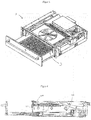
- a receptacle 1 of an embodiment of a kitchen cabinet according to the invention is shown, which has a drawer 2 and an inventive device 3 for cooking food.
- Figures 1 and 2 show this recording with closed drawer and FIGS. 3 and 4 show this recording with open drawer.
- the drawer 2 is longitudinally displaceably guided in the receptacle 1 and comprises a lower heating unit 100 of the device 3.
- This lower heating unit 100 is in FIG. 5 shown in enlarged view.
- the heating plate 101 comprises a heating plate 101, behind which an induction coil 102 is arranged.
- the heating plate 101 has a support surface 101a for toasting bread or for grilling or the like.
- the heating plate 101 and the induction coil 102 are arranged together in the carrier 103, which forms part of the drawer.
- the carrier 104 is made of a plastic material.
- the induction coil 102 is a current-carrying copper wire coil.
- the heating plate 101 is detachably attached to the heating unit 100 by being inserted into a recess 104 of the carrier 103.
- the heating plate 101 can therefore be reversibly removed from the heating unit 100 for cleaning.
- an intermediate plate 105 is arranged with a smooth and non-porous surface.
- the heating plate 101 lies completely on this surface. Between the induction coil 102 and the intermediate plate 105 spacers 106 are arranged.
- the intermediate plate 105 is made of Ceran®, a glass ceramic of Schott AG, whose main components are lithium, aluminum and silicon oxide. This material has high electric field permeability of the induction coil 102 and a small thermal expansion coefficient. It also has a low thermal conductivity, so that the waste heat of the overlying heating plate 101 in the operating state of the heating unit 100 is not transmitted too much to the plastic carrier 103.
- the intermediate plate covers the induction coil 102 completely and tightly, and is peripherally bonded to the support surface 104a in the receptacle 104. This prevents contamination of the induction coil 102 and allows easy cleaning of the drawer 2 with the heating plate removed.
- the heating plate 101 is made of a ferromagnetic iron alloy, which favors inductive heating. It has on the support surface 101 a for the food on a grooved structure to give the food the desired rust structure and to reduce sticking of the food.
- an upper heating plate 11 is disposed above the lower heating plate 9.
- the upper heating plate 11 comprises a grill plate 12 arranged on its underside, a heat generator 13 which is designed as a radiant heater and which is arranged on the upper side of the upper heating plate 11, and a cover 14 for the radiant heater which is located between the grill plate 12 and the heat generator 13 is arranged.
- the grill plate 12 is designed as a plate with transverse recesses on its underside. It is detachably attached to the upper heating plate 11 and can be removed in particular for cleaning purposes and then reattached.
- an upper heating unit 200 which is constructed similarly to the lower heating unit 100.
- only metal springs 207 are provided on the upper heating unit 200 in order to enable a reversibly detachable fastening of the heating plate 201, but at the same time to prevent a force-induced detachment from the intermediate plate 205.
- the upper heating unit 200 is mounted in the receptacle 1 so that the upper heating plate 201 moves from a first position (shown in FIG. 2 ) to a second position (shown in FIG. 4 ) emotional.
- upper heating unit 200 is pivotally attached to a first lever 10 and to a second lever 11 on the ceiling of the receptacle 1. Both levers 10 and 11 are closed attached to this purpose around an axis pivotally mounted on the ceiling of the receptacle 1.
- the second lever 11 includes a slot 12 for receiving a journal 208 on the upper heating unit 200.
- the slot 12 is curved along a circular path, wherein the circle center is defined by the pivot axis of the second lever 11.
- the second lever 11 is pivoted by force, whereby movement of the heating unit 200 from the first position to the second position and vice versa can be effected.
- the force can be generated by a motor or mechanically by moving the drawer.
- the drawer 2 is initially in the withdrawn state, the in FIGS. 3 and 4 is shown.
- the upper heating unit 200 is in the raised second position.
- the food can be placed on the heating plate 101.
- the drawer 2 is inserted into the receptacle 1.
Landscapes
- Engineering & Computer Science (AREA)
- Food Science & Technology (AREA)
- Chemical & Material Sciences (AREA)
- Combustion & Propulsion (AREA)
- Mechanical Engineering (AREA)
- General Engineering & Computer Science (AREA)
- Physics & Mathematics (AREA)
- Electromagnetism (AREA)
- Baking, Grill, Roasting (AREA)
- Electric Ovens (AREA)
- Electric Stoves And Ranges (AREA)
Claims (6)
- Dispositif (3) de cuisson de produits alimentaires comprenant un boîtier (1) ainsi qu'une plaque chauffante supérieure et une plaque chauffante inférieure (201, 101), au moins une plaque chauffante, de préférence la plaque chauffante supérieure (201) étant fixée de telle manière dans le boîtier (1) qu'elle peut être déplacée d'une première position à une seconde position,
les deux plaques chauffantes (101, 201) étant disposées parallèlement l'une à l'autre dans la première position et l'écart vertical entre les plaques chauffantes (101, 201) dans la seconde position étant au moins en partie supérieur à celui de la première position, un élément de chauffage (102, 202), et de préférence un élément de chauffage par induction, étant disposé derrière la plaque chauffante supérieure (201) et/ou la plaque chauffante inférieure (101) et formant conjointement avec la plaque chauffante (101, 201) associée une unité de chauffage supérieure ou inférieure (100, 200) ou une partie de celle-ci,
la plaque chauffante supérieure et/ou inférieure (101, 201) étant fixée de manière détachable à l'unité de chauffage (100, 200) respective,
caractérisé en ce que,
entre la plaque chauffante supérieure et/ou inférieure (201, 101) et l'élément de chauffage (102, 202) respectif, est disposée une plaque intermédiaire (105, 205), qui recouvre entièrement et de manière étanchéifiante l'élément de chauffage (102, 202) et qui est composée d'un matériau résistant à la chaleur et isolant électriquement, de préférence de vitrocéramique. - Dispositif selon la revendication 1, caractérisé en ce que la plaque chauffante supérieure et/ou la plaque chauffante inférieure (201, 101) comportent ou sont constituées d'un métal, et de préférence d'un matériau ferromagnétique, comme par exemple un alliage de fer.
- Dispositif selon l'une des revendications précédentes, caractérisé en ce que le boîtier (1) est le logement d'un meuble de cuisine, comprenant de préférence un tiroir (2).
- Dispositif selon la revendication 3, caractérisé en ce qu'au moins une unité de chauffage, de préférence l'unité de chauffage supérieure (200) est configurée ou est fixée de telle manière dans le logement que la plaque chauffante (101, 201) associée à celle-ci se déplace de la première position à la seconde position lors de l'ouverture du tiroir (2) ou après celle-ci.
- Dispositif selon la revendication 3 ou 4, caractérisé en ce qu'au moins une unité de chauffage, de préférence l'unité de chauffage inférieure (100) est fixée dans le tiroir (2).
- Meuble de cuisine comprenant un logement et un dispositif (3) de cuisson de produits alimentaires disposé dans ledit logement, dans lequel
le logement du meuble de cuisine est relié au boîtier (1) du dispositif ou représente le boîtier (1),
caractérisé en ce que le dispositif (3) est réalisé selon l'une des revendications précédentes.
Priority Applications (1)
| Application Number | Priority Date | Filing Date | Title |
|---|---|---|---|
| PL14174915T PL2853820T3 (pl) | 2013-09-04 | 2014-06-30 | Urządzenie do obróbki termicznej środków spożywczych |
Applications Claiming Priority (1)
| Application Number | Priority Date | Filing Date | Title |
|---|---|---|---|
| DE102013014719.0A DE102013014719A1 (de) | 2013-09-04 | 2013-09-04 | Vorrichtung zum Garen von Lebensmitteln |
Publications (2)
| Publication Number | Publication Date |
|---|---|
| EP2853820A1 EP2853820A1 (fr) | 2015-04-01 |
| EP2853820B1 true EP2853820B1 (fr) | 2017-11-29 |
Family
ID=51176913
Family Applications (1)
| Application Number | Title | Priority Date | Filing Date |
|---|---|---|---|
| EP14174915.0A Active EP2853820B1 (fr) | 2013-09-04 | 2014-06-30 | Dispositif de cuisson de produits alimentaires |
Country Status (5)
| Country | Link |
|---|---|
| EP (1) | EP2853820B1 (fr) |
| DE (1) | DE102013014719A1 (fr) |
| ES (1) | ES2660881T3 (fr) |
| PL (1) | PL2853820T3 (fr) |
| TR (1) | TR201802618T4 (fr) |
Cited By (1)
| Publication number | Priority date | Publication date | Assignee | Title |
|---|---|---|---|---|
| BE1029169B1 (de) * | 2021-03-03 | 2022-10-03 | Miele & Cie | Gargerät, vorzugsweise Einbaugargerät |
Families Citing this family (4)
| Publication number | Priority date | Publication date | Assignee | Title |
|---|---|---|---|---|
| DE102012025412A1 (de) * | 2012-12-20 | 2014-06-26 | Gronbach Forschungs- Und Entwicklungs Gmbh & Co. Kg | Gargerät |
| DE102021105078A1 (de) * | 2021-03-03 | 2022-09-08 | Miele & Cie. Kg | Gargerät |
| DE102021105039A1 (de) | 2021-03-03 | 2022-09-08 | Miele & Cie. Kg | Einbaugargerät |
| DE102022206183A1 (de) | 2022-06-21 | 2023-12-21 | BSH Hausgeräte GmbH | Dampfgarschublade mit Raumteiler und Heizelementen |
Citations (1)
| Publication number | Priority date | Publication date | Assignee | Title |
|---|---|---|---|---|
| EP1818620A1 (fr) * | 2006-02-10 | 2007-08-15 | Filippi S.r.l. | Four avec un chariot de four avec un elément chauffant intégré et de grilles de cuisson |
Family Cites Families (5)
| Publication number | Priority date | Publication date | Assignee | Title |
|---|---|---|---|---|
| DE10001330A1 (de) * | 2000-01-14 | 2001-07-19 | Heinrich Schuermann | Elektrokochplatte |
| ITPN20060081A1 (it) * | 2006-10-17 | 2008-04-18 | Electrolux Professional Spa | Dispositivo per la cottura rapida di alimenti su due lati opposti |
| DE102010036993B3 (de) * | 2010-08-13 | 2012-02-02 | Eisfink Max Maier Gmbh & Co. Kg | Koch- oder Grillplatte |
| DE102011101042A1 (de) | 2011-05-10 | 2012-11-15 | Gronbach Forschungs- Und Entwicklungs Gmbh & Co. Kg | Gargerät |
| DE102012003970B4 (de) * | 2012-02-29 | 2013-09-05 | Gronbach Forschungs- Und Entwicklungs Gmbh & Co. Kg | Gargerät |
-
2013
- 2013-09-04 DE DE102013014719.0A patent/DE102013014719A1/de not_active Withdrawn
-
2014
- 2014-06-30 TR TR2018/02618T patent/TR201802618T4/tr unknown
- 2014-06-30 ES ES14174915.0T patent/ES2660881T3/es active Active
- 2014-06-30 EP EP14174915.0A patent/EP2853820B1/fr active Active
- 2014-06-30 PL PL14174915T patent/PL2853820T3/pl unknown
Patent Citations (1)
| Publication number | Priority date | Publication date | Assignee | Title |
|---|---|---|---|---|
| EP1818620A1 (fr) * | 2006-02-10 | 2007-08-15 | Filippi S.r.l. | Four avec un chariot de four avec un elément chauffant intégré et de grilles de cuisson |
Cited By (1)
| Publication number | Priority date | Publication date | Assignee | Title |
|---|---|---|---|---|
| BE1029169B1 (de) * | 2021-03-03 | 2022-10-03 | Miele & Cie | Gargerät, vorzugsweise Einbaugargerät |
Also Published As
| Publication number | Publication date |
|---|---|
| TR201802618T4 (tr) | 2018-03-21 |
| EP2853820A1 (fr) | 2015-04-01 |
| ES2660881T3 (es) | 2018-03-26 |
| PL2853820T3 (pl) | 2018-04-30 |
| DE102013014719A1 (de) | 2015-03-05 |
Similar Documents
| Publication | Publication Date | Title |
|---|---|---|
| EP1075204B1 (fr) | Procede pour rechauffer des aliments deja prepares | |
| EP2853820A1 (fr) | Dispositif de cuisson de produits alimentaires | |
| DE2809884A1 (de) | Kochgeraet | |
| DE602005005680T2 (de) | Vorrichtung zum beibehalten einer temperatur in nahrungsmitteln und getränken | |
| DE102009029464B4 (de) | Garraumvorrichtung mit CNT-Heizelement | |
| EP2746670B1 (fr) | Appareil de cuisson | |
| DE8508617U1 (de) | Einschiebbarer oder einlegbarer Backboden für einen Backofen | |
| DE102007004275A1 (de) | Vorrichtung zur Wandlung induktiv übertragener elektrischer Energie und Verfahren zur Herstellung einer derartigen Vorrichtung | |
| DE60004581T2 (de) | Herausnehmbare Heizbaugruppe für Elektroherd | |
| EP2658341B1 (fr) | Système doté d'un champ de cuisson et d'au moins une unité de plaque de champ de cuisson amovible | |
| EP3384817B1 (fr) | Installation de cuisson destinée à la préparation d'un produit à cuire | |
| DE202005002549U1 (de) | Gargutträger | |
| EP2765827B1 (fr) | Dispositif de plaque de cuisson | |
| DE102011055931A1 (de) | Heizelement | |
| DE102009019765A1 (de) | Grillvorrichtung für ein Induktionskochfeld | |
| DE102009026111A1 (de) | Kochgerät und insbesondere dafür vorgessehener gelochter GN-Behälter | |
| EP1880635A1 (fr) | Chariot de transport de repas | |
| DE596315C (de) | Anordnung fuer elektrisch beheizte Bratpfannen | |
| DE202006005171U1 (de) | GN-Behälter und insbesondere damit ausgerüstetes Kochsystem | |
| EP2025267B1 (fr) | Chambre d'infusion en matière plastique renforcée de fibres de carbone | |
| EP3210508B1 (fr) | Gril électrique | |
| DE4000536C2 (fr) | ||
| EP0697567B1 (fr) | Unités de cuisson combinées pour préparer des denrées chaudes | |
| DE20021753U1 (de) | Geschirrteil | |
| EP2463589A1 (fr) | Champ de cuisson à induction doté d'une plaque de cuisson et d'un inducteur agencé sous la plaque de cuisson |
Legal Events
| Date | Code | Title | Description |
|---|---|---|---|
| PUAI | Public reference made under article 153(3) epc to a published international application that has entered the european phase |
Free format text: ORIGINAL CODE: 0009012 |
|
| 17P | Request for examination filed |
Effective date: 20140630 |
|
| AK | Designated contracting states |
Kind code of ref document: A1 Designated state(s): AL AT BE BG CH CY CZ DE DK EE ES FI FR GB GR HR HU IE IS IT LI LT LU LV MC MK MT NL NO PL PT RO RS SE SI SK SM TR |
|
| AX | Request for extension of the european patent |
Extension state: BA ME |
|
| REG | Reference to a national code |
Ref country code: DE Ref legal event code: R079 Ref document number: 502014006377 Country of ref document: DE Free format text: PREVIOUS MAIN CLASS: F24C0015000000 Ipc: F24C0015160000 |
|
| RIC1 | Information provided on ipc code assigned before grant |
Ipc: F24C 15/16 20060101AFI20161103BHEP Ipc: A47J 37/06 20060101ALI20161103BHEP |
|
| 17Q | First examination report despatched |
Effective date: 20161201 |
|
| GRAP | Despatch of communication of intention to grant a patent |
Free format text: ORIGINAL CODE: EPIDOSNIGR1 |
|
| INTG | Intention to grant announced |
Effective date: 20170720 |
|
| GRAS | Grant fee paid |
Free format text: ORIGINAL CODE: EPIDOSNIGR3 |
|
| GRAA | (expected) grant |
Free format text: ORIGINAL CODE: 0009210 |
|
| AK | Designated contracting states |
Kind code of ref document: B1 Designated state(s): AL AT BE BG CH CY CZ DE DK EE ES FI FR GB GR HR HU IE IS IT LI LT LU LV MC MK MT NL NO PL PT RO RS SE SI SK SM TR |
|
| REG | Reference to a national code |
Ref country code: CH Ref legal event code: EP |
|
| REG | Reference to a national code |
Ref country code: AT Ref legal event code: REF Ref document number: 950738 Country of ref document: AT Kind code of ref document: T Effective date: 20171215 |
|
| REG | Reference to a national code |
Ref country code: IE Ref legal event code: FG4D Free format text: LANGUAGE OF EP DOCUMENT: GERMAN |
|
| REG | Reference to a national code |
Ref country code: DE Ref legal event code: R096 Ref document number: 502014006377 Country of ref document: DE |
|
| REG | Reference to a national code |
Ref country code: CH Ref legal event code: NV Representative=s name: KELLER AND PARTNER PATENTANWAELTE AG, CH |
|
| REG | Reference to a national code |
Ref country code: NL Ref legal event code: FP |
|
| REG | Reference to a national code |
Ref country code: ES Ref legal event code: FG2A Ref document number: 2660881 Country of ref document: ES Kind code of ref document: T3 Effective date: 20180326 |
|
| REG | Reference to a national code |
Ref country code: LT Ref legal event code: MG4D |
|
| PG25 | Lapsed in a contracting state [announced via postgrant information from national office to epo] |
Ref country code: LT Free format text: LAPSE BECAUSE OF FAILURE TO SUBMIT A TRANSLATION OF THE DESCRIPTION OR TO PAY THE FEE WITHIN THE PRESCRIBED TIME-LIMIT Effective date: 20171129 Ref country code: SE Free format text: LAPSE BECAUSE OF FAILURE TO SUBMIT A TRANSLATION OF THE DESCRIPTION OR TO PAY THE FEE WITHIN THE PRESCRIBED TIME-LIMIT Effective date: 20171129 Ref country code: FI Free format text: LAPSE BECAUSE OF FAILURE TO SUBMIT A TRANSLATION OF THE DESCRIPTION OR TO PAY THE FEE WITHIN THE PRESCRIBED TIME-LIMIT Effective date: 20171129 Ref country code: NO Free format text: LAPSE BECAUSE OF FAILURE TO SUBMIT A TRANSLATION OF THE DESCRIPTION OR TO PAY THE FEE WITHIN THE PRESCRIBED TIME-LIMIT Effective date: 20180228 |
|
| PG25 | Lapsed in a contracting state [announced via postgrant information from national office to epo] |
Ref country code: RS Free format text: LAPSE BECAUSE OF FAILURE TO SUBMIT A TRANSLATION OF THE DESCRIPTION OR TO PAY THE FEE WITHIN THE PRESCRIBED TIME-LIMIT Effective date: 20171129 Ref country code: GR Free format text: LAPSE BECAUSE OF FAILURE TO SUBMIT A TRANSLATION OF THE DESCRIPTION OR TO PAY THE FEE WITHIN THE PRESCRIBED TIME-LIMIT Effective date: 20180301 Ref country code: HR Free format text: LAPSE BECAUSE OF FAILURE TO SUBMIT A TRANSLATION OF THE DESCRIPTION OR TO PAY THE FEE WITHIN THE PRESCRIBED TIME-LIMIT Effective date: 20171129 Ref country code: BG Free format text: LAPSE BECAUSE OF FAILURE TO SUBMIT A TRANSLATION OF THE DESCRIPTION OR TO PAY THE FEE WITHIN THE PRESCRIBED TIME-LIMIT Effective date: 20180228 Ref country code: LV Free format text: LAPSE BECAUSE OF FAILURE TO SUBMIT A TRANSLATION OF THE DESCRIPTION OR TO PAY THE FEE WITHIN THE PRESCRIBED TIME-LIMIT Effective date: 20171129 |
|
| REG | Reference to a national code |
Ref country code: FR Ref legal event code: PLFP Year of fee payment: 5 |
|
| PG25 | Lapsed in a contracting state [announced via postgrant information from national office to epo] |
Ref country code: DK Free format text: LAPSE BECAUSE OF FAILURE TO SUBMIT A TRANSLATION OF THE DESCRIPTION OR TO PAY THE FEE WITHIN THE PRESCRIBED TIME-LIMIT Effective date: 20171129 Ref country code: CZ Free format text: LAPSE BECAUSE OF FAILURE TO SUBMIT A TRANSLATION OF THE DESCRIPTION OR TO PAY THE FEE WITHIN THE PRESCRIBED TIME-LIMIT Effective date: 20171129 Ref country code: EE Free format text: LAPSE BECAUSE OF FAILURE TO SUBMIT A TRANSLATION OF THE DESCRIPTION OR TO PAY THE FEE WITHIN THE PRESCRIBED TIME-LIMIT Effective date: 20171129 Ref country code: CY Free format text: LAPSE BECAUSE OF FAILURE TO SUBMIT A TRANSLATION OF THE DESCRIPTION OR TO PAY THE FEE WITHIN THE PRESCRIBED TIME-LIMIT Effective date: 20171129 |
|
| REG | Reference to a national code |
Ref country code: DE Ref legal event code: R097 Ref document number: 502014006377 Country of ref document: DE |
|
| PG25 | Lapsed in a contracting state [announced via postgrant information from national office to epo] |
Ref country code: SM Free format text: LAPSE BECAUSE OF FAILURE TO SUBMIT A TRANSLATION OF THE DESCRIPTION OR TO PAY THE FEE WITHIN THE PRESCRIBED TIME-LIMIT Effective date: 20171129 |
|
| PG25 | Lapsed in a contracting state [announced via postgrant information from national office to epo] |
Ref country code: MT Free format text: LAPSE BECAUSE OF FAILURE TO SUBMIT A TRANSLATION OF THE DESCRIPTION OR TO PAY THE FEE WITHIN THE PRESCRIBED TIME-LIMIT Effective date: 20171129 |
|
| PLBE | No opposition filed within time limit |
Free format text: ORIGINAL CODE: 0009261 |
|
| STAA | Information on the status of an ep patent application or granted ep patent |
Free format text: STATUS: NO OPPOSITION FILED WITHIN TIME LIMIT |
|
| 26N | No opposition filed |
Effective date: 20180830 |
|
| PG25 | Lapsed in a contracting state [announced via postgrant information from national office to epo] |
Ref country code: SI Free format text: LAPSE BECAUSE OF FAILURE TO SUBMIT A TRANSLATION OF THE DESCRIPTION OR TO PAY THE FEE WITHIN THE PRESCRIBED TIME-LIMIT Effective date: 20171129 |
|
| PG25 | Lapsed in a contracting state [announced via postgrant information from national office to epo] |
Ref country code: LU Free format text: LAPSE BECAUSE OF NON-PAYMENT OF DUE FEES Effective date: 20180630 Ref country code: MC Free format text: LAPSE BECAUSE OF FAILURE TO SUBMIT A TRANSLATION OF THE DESCRIPTION OR TO PAY THE FEE WITHIN THE PRESCRIBED TIME-LIMIT Effective date: 20171129 |
|
| REG | Reference to a national code |
Ref country code: IE Ref legal event code: MM4A |
|
| PG25 | Lapsed in a contracting state [announced via postgrant information from national office to epo] |
Ref country code: IE Free format text: LAPSE BECAUSE OF NON-PAYMENT OF DUE FEES Effective date: 20180630 |
|
| REG | Reference to a national code |
Ref country code: DE Ref legal event code: R082 Ref document number: 502014006377 Country of ref document: DE Representative=s name: HOFSTETTER, SCHURACK & PARTNER PATENT- UND REC, DE Ref country code: DE Ref legal event code: R082 Ref document number: 502014006377 Country of ref document: DE Representative=s name: HOFSTETTER, SCHURACK & PARTNER - PATENT- UND R, DE |
|
| PGFP | Annual fee paid to national office [announced via postgrant information from national office to epo] |
Ref country code: PL Payment date: 20190529 Year of fee payment: 6 Ref country code: NL Payment date: 20190623 Year of fee payment: 6 |
|
| PGFP | Annual fee paid to national office [announced via postgrant information from national office to epo] |
Ref country code: BE Payment date: 20190626 Year of fee payment: 6 Ref country code: FR Payment date: 20190625 Year of fee payment: 6 Ref country code: TR Payment date: 20190624 Year of fee payment: 6 |
|
| PGFP | Annual fee paid to national office [announced via postgrant information from national office to epo] |
Ref country code: SK Payment date: 20190603 Year of fee payment: 6 Ref country code: CH Payment date: 20190627 Year of fee payment: 6 |
|
| PGFP | Annual fee paid to national office [announced via postgrant information from national office to epo] |
Ref country code: GB Payment date: 20190627 Year of fee payment: 6 Ref country code: ES Payment date: 20190712 Year of fee payment: 6 Ref country code: IT Payment date: 20190628 Year of fee payment: 6 |
|
| PG25 | Lapsed in a contracting state [announced via postgrant information from national office to epo] |
Ref country code: HU Free format text: LAPSE BECAUSE OF FAILURE TO SUBMIT A TRANSLATION OF THE DESCRIPTION OR TO PAY THE FEE WITHIN THE PRESCRIBED TIME-LIMIT; INVALID AB INITIO Effective date: 20140630 Ref country code: PT Free format text: LAPSE BECAUSE OF FAILURE TO SUBMIT A TRANSLATION OF THE DESCRIPTION OR TO PAY THE FEE WITHIN THE PRESCRIBED TIME-LIMIT Effective date: 20171129 |
|
| PG25 | Lapsed in a contracting state [announced via postgrant information from national office to epo] |
Ref country code: MK Free format text: LAPSE BECAUSE OF NON-PAYMENT OF DUE FEES Effective date: 20171129 Ref country code: RO Free format text: LAPSE BECAUSE OF FAILURE TO SUBMIT A TRANSLATION OF THE DESCRIPTION OR TO PAY THE FEE WITHIN THE PRESCRIBED TIME-LIMIT Effective date: 20171129 |
|
| PG25 | Lapsed in a contracting state [announced via postgrant information from national office to epo] |
Ref country code: AL Free format text: LAPSE BECAUSE OF FAILURE TO SUBMIT A TRANSLATION OF THE DESCRIPTION OR TO PAY THE FEE WITHIN THE PRESCRIBED TIME-LIMIT Effective date: 20171129 Ref country code: IS Free format text: LAPSE BECAUSE OF FAILURE TO SUBMIT A TRANSLATION OF THE DESCRIPTION OR TO PAY THE FEE WITHIN THE PRESCRIBED TIME-LIMIT Effective date: 20180329 |
|
| REG | Reference to a national code |
Ref country code: CH Ref legal event code: PFA Owner name: GRONBACH FORSCHUNGS- UND ENTWICKLUNGS GMBH AND, AT Free format text: FORMER OWNER: GRONBACH FORSCHUNGS- UND ENTWICKLUNGS GMBH AND CO. KG, AT |
|
| REG | Reference to a national code |
Ref country code: CH Ref legal event code: PL |
|
| REG | Reference to a national code |
Ref country code: NL Ref legal event code: MM Effective date: 20200701 |
|
| REG | Reference to a national code |
Ref country code: SK Ref legal event code: MM4A Ref document number: E 26422 Country of ref document: SK Effective date: 20200630 |
|
| GBPC | Gb: european patent ceased through non-payment of renewal fee |
Effective date: 20200630 |
|
| REG | Reference to a national code |
Ref country code: BE Ref legal event code: MM Effective date: 20200630 |
|
| PG25 | Lapsed in a contracting state [announced via postgrant information from national office to epo] |
Ref country code: NL Free format text: LAPSE BECAUSE OF NON-PAYMENT OF DUE FEES Effective date: 20200701 Ref country code: FR Free format text: LAPSE BECAUSE OF NON-PAYMENT OF DUE FEES Effective date: 20200630 Ref country code: CH Free format text: LAPSE BECAUSE OF NON-PAYMENT OF DUE FEES Effective date: 20200630 Ref country code: LI Free format text: LAPSE BECAUSE OF NON-PAYMENT OF DUE FEES Effective date: 20200630 Ref country code: GB Free format text: LAPSE BECAUSE OF NON-PAYMENT OF DUE FEES Effective date: 20200630 |
|
| PG25 | Lapsed in a contracting state [announced via postgrant information from national office to epo] |
Ref country code: BE Free format text: LAPSE BECAUSE OF NON-PAYMENT OF DUE FEES Effective date: 20200630 |
|
| PG25 | Lapsed in a contracting state [announced via postgrant information from national office to epo] |
Ref country code: SK Free format text: LAPSE BECAUSE OF NON-PAYMENT OF DUE FEES Effective date: 20200630 |
|
| PG25 | Lapsed in a contracting state [announced via postgrant information from national office to epo] |
Ref country code: IT Free format text: LAPSE BECAUSE OF NON-PAYMENT OF DUE FEES Effective date: 20200630 |
|
| REG | Reference to a national code |
Ref country code: ES Ref legal event code: FD2A Effective date: 20211129 |
|
| PG25 | Lapsed in a contracting state [announced via postgrant information from national office to epo] |
Ref country code: ES Free format text: LAPSE BECAUSE OF NON-PAYMENT OF DUE FEES Effective date: 20200701 |
|
| PG25 | Lapsed in a contracting state [announced via postgrant information from national office to epo] |
Ref country code: TR Free format text: LAPSE BECAUSE OF NON-PAYMENT OF DUE FEES Effective date: 20200630 |
|
| PG25 | Lapsed in a contracting state [announced via postgrant information from national office to epo] |
Ref country code: PL Free format text: LAPSE BECAUSE OF NON-PAYMENT OF DUE FEES Effective date: 20200630 |
|
| P01 | Opt-out of the competence of the unified patent court (upc) registered |
Effective date: 20230602 |
|
| PGFP | Annual fee paid to national office [announced via postgrant information from national office to epo] |
Ref country code: AT Payment date: 20250616 Year of fee payment: 12 |
|
| PGFP | Annual fee paid to national office [announced via postgrant information from national office to epo] |
Ref country code: DE Payment date: 20250626 Year of fee payment: 12 |