EP2853841A1 - Procédé de refroidissement de composants d'une machine de formage par soufflage et/ou d'une machine de remplissage de boissons - Google Patents
Procédé de refroidissement de composants d'une machine de formage par soufflage et/ou d'une machine de remplissage de boissons Download PDFInfo
- Publication number
- EP2853841A1 EP2853841A1 EP20140179665 EP14179665A EP2853841A1 EP 2853841 A1 EP2853841 A1 EP 2853841A1 EP 20140179665 EP20140179665 EP 20140179665 EP 14179665 A EP14179665 A EP 14179665A EP 2853841 A1 EP2853841 A1 EP 2853841A1
- Authority
- EP
- European Patent Office
- Prior art keywords
- refrigeration system
- working fluid
- evaporator
- condenser
- cooling
- Prior art date
- Legal status (The legal status is an assumption and is not a legal conclusion. Google has not performed a legal analysis and makes no representation as to the accuracy of the status listed.)
- Withdrawn
Links
- 238000001816 cooling Methods 0.000 title claims abstract description 45
- 235000013361 beverage Nutrition 0.000 title claims abstract description 41
- 238000000034 method Methods 0.000 title claims abstract description 28
- 238000000071 blow moulding Methods 0.000 title claims abstract description 25
- 238000005057 refrigeration Methods 0.000 claims abstract description 105
- 239000012530 fluid Substances 0.000 claims abstract description 69
- 238000004519 manufacturing process Methods 0.000 claims abstract description 39
- 230000007613 environmental effect Effects 0.000 claims abstract description 8
- XLYOFNOQVPJJNP-UHFFFAOYSA-N water Substances O XLYOFNOQVPJJNP-UHFFFAOYSA-N 0.000 claims description 22
- 238000010438 heat treatment Methods 0.000 claims description 7
- 239000012080 ambient air Substances 0.000 claims description 3
- 238000007664 blowing Methods 0.000 claims description 2
- 239000007789 gas Substances 0.000 description 9
- 239000002918 waste heat Substances 0.000 description 6
- 239000003570 air Substances 0.000 description 4
- 238000001704 evaporation Methods 0.000 description 3
- 239000000463 material Substances 0.000 description 3
- QGZKDVFQNNGYKY-UHFFFAOYSA-N Ammonia Chemical group N QGZKDVFQNNGYKY-UHFFFAOYSA-N 0.000 description 2
- 238000009833 condensation Methods 0.000 description 2
- 230000005494 condensation Effects 0.000 description 2
- 230000008020 evaporation Effects 0.000 description 2
- 239000003507 refrigerant Substances 0.000 description 2
- CBENFWSGALASAD-UHFFFAOYSA-N Ozone Chemical compound [O-][O+]=O CBENFWSGALASAD-UHFFFAOYSA-N 0.000 description 1
- 229910021529 ammonia Inorganic materials 0.000 description 1
- 230000001419 dependent effect Effects 0.000 description 1
- 238000010586 diagram Methods 0.000 description 1
- 238000004870 electrical engineering Methods 0.000 description 1
- 230000002427 irreversible effect Effects 0.000 description 1
- 238000000465 moulding Methods 0.000 description 1
- 238000013021 overheating Methods 0.000 description 1
- 230000000704 physical effect Effects 0.000 description 1
- 239000000126 substance Substances 0.000 description 1
- 238000005496 tempering Methods 0.000 description 1
Images
Classifications
-
- F—MECHANICAL ENGINEERING; LIGHTING; HEATING; WEAPONS; BLASTING
- F25—REFRIGERATION OR COOLING; COMBINED HEATING AND REFRIGERATION SYSTEMS; HEAT PUMP SYSTEMS; MANUFACTURE OR STORAGE OF ICE; LIQUEFACTION SOLIDIFICATION OF GASES
- F25B—REFRIGERATION MACHINES, PLANTS OR SYSTEMS; COMBINED HEATING AND REFRIGERATION SYSTEMS; HEAT PUMP SYSTEMS
- F25B1/00—Compression machines, plants or systems with non-reversible cycle
- F25B1/10—Compression machines, plants or systems with non-reversible cycle with multi-stage compression
-
- B—PERFORMING OPERATIONS; TRANSPORTING
- B29—WORKING OF PLASTICS; WORKING OF SUBSTANCES IN A PLASTIC STATE IN GENERAL
- B29C—SHAPING OR JOINING OF PLASTICS; SHAPING OF MATERIAL IN A PLASTIC STATE, NOT OTHERWISE PROVIDED FOR; AFTER-TREATMENT OF THE SHAPED PRODUCTS, e.g. REPAIRING
- B29C49/00—Blow-moulding, i.e. blowing a preform or parison to a desired shape within a mould; Apparatus therefor
- B29C49/42—Component parts, details or accessories; Auxiliary operations
- B29C49/4239—Avoiding condense, e.g. on cooled mould surfaces
-
- B—PERFORMING OPERATIONS; TRANSPORTING
- B29—WORKING OF PLASTICS; WORKING OF SUBSTANCES IN A PLASTIC STATE IN GENERAL
- B29C—SHAPING OR JOINING OF PLASTICS; SHAPING OF MATERIAL IN A PLASTIC STATE, NOT OTHERWISE PROVIDED FOR; AFTER-TREATMENT OF THE SHAPED PRODUCTS, e.g. REPAIRING
- B29C49/00—Blow-moulding, i.e. blowing a preform or parison to a desired shape within a mould; Apparatus therefor
- B29C49/42—Component parts, details or accessories; Auxiliary operations
- B29C49/64—Heating or cooling preforms, parisons or blown articles
- B29C49/6409—Thermal conditioning of preforms
- B29C49/6427—Cooling of preforms
-
- B—PERFORMING OPERATIONS; TRANSPORTING
- B67—OPENING, CLOSING OR CLEANING BOTTLES, JARS OR SIMILAR CONTAINERS; LIQUID HANDLING
- B67C—CLEANING, FILLING WITH LIQUIDS OR SEMILIQUIDS, OR EMPTYING, OF BOTTLES, JARS, CANS, CASKS, BARRELS, OR SIMILAR CONTAINERS, NOT OTHERWISE PROVIDED FOR; FUNNELS
- B67C3/00—Bottling liquids or semiliquids; Filling jars or cans with liquids or semiliquids using bottling or like apparatus; Filling casks or barrels with liquids or semiliquids
- B67C3/02—Bottling liquids or semiliquids; Filling jars or cans with liquids or semiliquids using bottling or like apparatus
- B67C3/22—Details
-
- F—MECHANICAL ENGINEERING; LIGHTING; HEATING; WEAPONS; BLASTING
- F25—REFRIGERATION OR COOLING; COMBINED HEATING AND REFRIGERATION SYSTEMS; HEAT PUMP SYSTEMS; MANUFACTURE OR STORAGE OF ICE; LIQUEFACTION SOLIDIFICATION OF GASES
- F25B—REFRIGERATION MACHINES, PLANTS OR SYSTEMS; COMBINED HEATING AND REFRIGERATION SYSTEMS; HEAT PUMP SYSTEMS
- F25B1/00—Compression machines, plants or systems with non-reversible cycle
-
- B—PERFORMING OPERATIONS; TRANSPORTING
- B67—OPENING, CLOSING OR CLEANING BOTTLES, JARS OR SIMILAR CONTAINERS; LIQUID HANDLING
- B67C—CLEANING, FILLING WITH LIQUIDS OR SEMILIQUIDS, OR EMPTYING, OF BOTTLES, JARS, CANS, CASKS, BARRELS, OR SIMILAR CONTAINERS, NOT OTHERWISE PROVIDED FOR; FUNNELS
- B67C3/00—Bottling liquids or semiliquids; Filling jars or cans with liquids or semiliquids using bottling or like apparatus; Filling casks or barrels with liquids or semiliquids
- B67C3/02—Bottling liquids or semiliquids; Filling jars or cans with liquids or semiliquids using bottling or like apparatus
- B67C3/22—Details
- B67C2003/227—Additional apparatus related to blow-moulding of the containers, e.g. a complete production line forming filled containers from preforms
Definitions
- the present invention relates to a method for cooling components of a container production plant and / or a beverage filling machine which heat during a blow molding process and / or a beverage production process.
- the present invention furthermore relates to a cooling system for cooling during a blow molding process and / or a beverage production process heating components of a container production plant and / or a beverage filling plant according to the preamble of claim 12 and a container production plant and a beverage filling machine according to the preambles of claims 13 and 14th
- refrigeration systems which are used for cooling of, for example, blow molds, which are based on evaporation of at least largely environmentally harmful or person-endangering refrigerants.
- refrigerants are working fluids which contain a hydrofluorocarbon (CFC) or develop a CFC during evaporation or it is an ammonia.
- CFC hydrofluorocarbon
- Such refrigeration systems for cooling the blow molds described above are particularly inexpensive to install and / or in operation, however, such environmentally friendly working fluids based refrigeration systems have a relatively low electrical efficiency.
- heat pumps are already known, which as a working fluid environment or persons unhindered, that is environmentally friendly, are.
- working fluids are biodegradable.
- Such heat pumps are used, for example, as geothermal heating systems for houses, where the working fluid may also be, for example, water.
- Such heat pumps can also be accommodated without problems in, for example, single-family homes, since there, in particular in the basement area, there is sufficient space for mounting such water-based heat pumps.
- heat pumps of this type can hitherto not be used, for example because of their space requirement and / or because of their other structural configurations, for cooling during a blow molding process and / or a beverage production process.
- the method for cooling claimed here makes use of at least one refrigeration system, wherein the refrigeration system is formed with an evaporator, a condenser and a gas region which extends between the evaporator and the condenser and is designed to supply working fluid evaporated by the evaporator to the condenser to conduct, so that the evaporated working fluid is liquefied in the condenser.
- the present invention makes use, inter alia, of the idea of using an environmentally friendly fluid as the working fluid use, which is deliverable in an environment of the blow molding machine and / or the beverage filling machine without causing environmental damage.
- "damage to the environment” includes all damages that occur on a Person and / or an environment of the blow molding machine and / or beverage filling machine may arise.
- environmental damage may be irreversible damage.
- the method for cooling components of a container production plant and / or a beverage filling machine that heat during a blow molding process and / or a beverage production process comprises at least one refrigeration system, wherein the refrigeration system comprises an evaporator, a liquefier and a gas region which is located between the evaporator and the condenser extends and is configured to direct working fluid evaporated from the evaporator to the condenser so that the vaporized working fluid in the condenser is liquefied.
- the working fluid is an environmentally friendly fluid which can be released into an environment of the blow molding machine and / or the beverage filling machine without causing environmental damage.
- the vaporized working fluid is free from fluorocarbons (CFCs). While such hydrofluorocarbons do not directly harm the environment, such fluorocarbons, when released into the atmosphere of the earth, have a physical and / or chemical invasive action thereon, for example on the earth's gas and ozone layers, such that by avoiding Hydrofluorocarbons in the working fluid are prevented from causing atmospheric shifts and / or disturbances upon release to the environment.
- CFCs fluorocarbons
- the refrigeration system is completely integrated into the container production plant and / or the beverage filling machine. That is, in one such embodiment, the refrigeration system is a component at least partially installed within the container production line and / or the beverage filling machine. In this respect, it is ensured that a particularly compact, time-saving and cost-effective method of cooling is offered, in which the refrigeration system, for example, can be set up particularly mobile together with the container production plant and / or the beverage filling machine and then put into operation.
- Such a refrigeration system is therefore not only particularly mobile, but also environmentally friendly, so that present in a particularly advantageous manner both a method of cooling with a particularly high electrical efficiency and a particularly mobile and variable usability of the refrigeration system is guaranteed.
- the refrigeration system is designed to cool blow molds for producing containers of the container production plant.
- the blow molds can be identified as the components. Blow molding, especially during the molding and blow molding process, is often exposed to very high heat sources, thereby undesirably heating the blow molds, for example during the blow molding process, especially at very short cycle times and high throughput speeds. The heating can go so far that the blow molds, in particular the material with which the blow molds are formed, carry material damage and / or structural changes, for example undesirable deformations. Due to an insufficient tempering or cooling of the blow molds, the quality of the containers produced in these blow molds can not be ensured.
- the refrigeration system described here it can be avoided that the blow molds heat up too much in such an undesirable manner.
- the ambient air is used to transfer heat from the blow molds to the working fluid of the refrigeration system.
- This offers the advantage that a heat exchange is made possible in a particularly simple manner via a spatially close arrangement of the blow molds to fluid lines of the refrigeration system by the heat transfer by means of the air without the refrigeration system would have to be connected by special mechanical structures for heat transfer with the blow molds ,
- the blow molds are in direct contact with fluid lines of the refrigeration system for heat transfer from the blow molds, the heat being transferred from the blow molds to the fluid lines of the refrigeration system via the direct contact via the fluid lines.
- Direct contact may mean that the blow molds are formed at least in places on the fluid lines or between the blow molds and the fluid lines at least one intermediate layer for improved heat transfer is arranged. In any case, this embodiment dispenses with the heat transfer to an air gap. In such an embodiment of the refrigeration system, it is ensured that the blow molds themselves are particularly efficient due to the continuous fluid exchange within the fluid lines and the direct contact of the fluid lines with the blow molds and can be cooled quickly.
- the critical temperature is in this case the temperature at which the blow molds for the blow molds leave characteristic working parameters.
- the working parameters may be, for example, a limit temperature or a minimum material rigidity.
- the blow molds of the container production plant are cooled before, during and / or after a blowing process within the container production plant by means of the refrigeration system.
- a particularly individual cooling especially in terms of time, guaranteed.
- a cooling of the blow molds for example by means of the previously described fluid line, can be set.
- the blow molds are already cooled down below a pre-blow temperature in order, as it were, to prevent overheating, at least in terms of time, in advance.
- the working fluid is water and the vaporized working fluid is water vapor, where a pressure in the evaporator in a refrigeration plant operation is less than 50 mbar and where a pressure in the gas region in a refrigeration plant operation is less than 200 mbar. It has been found that an efficiency of the entire refrigeration system at such pressure ratios with water as the working fluid is greatest.
- water as a working fluid is particularly environmentally friendly and not only inexpensive in the refrigeration system filled, but particularly suitable by its physical properties, in addition to maximize efficiency, especially an electrical efficiency of the entire refrigeration system as possible.
- the refrigeration system further comprises a compressor, wherein the compressor is disposed between the evaporator and the condenser, wherein the compressor is configured to compress vaporized working fluid and to feed the compressed working fluid into a part of the gas region which is higher in pressure than the evaporator has in one operation of the refrigeration system.
- the condenser can be arranged in an operating setup direction of the refrigeration system above the evaporator be.
- One advantage is that the transport of the vaporized working fluid from bottom to top can be carried out in an energy-efficient manner since the working fluid in vaporized form has less weight, so that less energy is required for this light weight to overcome the height difference from the evaporator outlet to the condenser inlet.
- a cooling is undertaken by means of at least two refrigeration systems according to at least one of the preceding embodiments, wherein the at least two refrigeration systems are connected in series in order to increase the pressure in the form of a cascade.
- the two refrigeration systems can be completely integrated in the container production plant and / or the beverage filling machine.
- a refrigeration system device is realized, comprising the at least two refrigeration systems, so that, inter alia, in such a configuration in the form of the cascade described here, the entire refrigeration system device is integrated in a particularly compact and cost-effective manner in the blow molding machine and / or beverage filling machine.
- the cooling is undertaken by means of at least two refrigeration systems according to at least one of the preceding embodiments, wherein the at least two refrigeration systems are connected in parallel side by side for increased performance.
- the waste heat outputs of both refrigeration systems a common end point and are merged, for example in a common fluid gas line and / or fluid line.
- such a parallel circuit for example in the form of a corresponding "parallel circuit in electrical engineering" realized.
- a mixed form of a cascaded and a parallel arrangement is also conceivable.
- two or more refrigeration systems are first connected in parallel to increase performance and are combined together in an input of a further connected behind such a parallel circuit of the refrigeration systems further refrigeration system and flow together.
- any form of a hybrid form comprising a parallel connection of refrigeration systems and a sequential cascaded arrangement of at least one further refrigeration system with the parallel circuit or vice versa is possible, so that in particular for individual pressure and power setting of the refrigeration system and thus the entire refrigeration system a particular efficient possibility of increasing the electrical efficiency with a fundamental environmental friendliness of the entire refrigeration system is possible.
- a refrigeration system for cooling components that heat up during a blow molding process and / or a beverage production process is specified.
- a method as described in connection with one or more of the abovementioned embodiments can be carried out by means of the refrigeration system described here. That is, the features listed for the method described here are also disclosed for the refrigeration system described here and vice versa.
- the refrigeration system described here can be installed in a container production plant or a beverage filling machine and integrated, for example.
- the refrigeration system comprises an evaporator, a condenser and a gas region which is between the evaporator and condenser is extended and formed to direct working fluid evaporated from the evaporator to the condenser, so that the evaporated working fluid in the condenser is liquefied.
- the working fluid is an environmentally friendly fluid which can be dispensed into an environment of the blow molding machine and / or the beverage filling machine without causing environmental damage.
- the refrigeration system described here has the same advantages as in connection with the method described here.
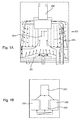
- Fig. 1A is shown in a schematic side view of a first embodiment of a refrigeration system 300 described here. It can be seen that the refrigeration system 300 with an evaporator 301, a condenser 302 and a gas region 303, which extends between the evaporator 301 and the condenser 302 and is designed to conduct working fluid evaporated by the evaporator 301 to the condenser 302 that the vaporized working fluid in the condenser 302 is liquefied.
- the present working fluid which is water
- passed through or in the area of the evaporator 301 first evaporates and ascends in the direction of the arrow to the condenser 302, which is arranged vertically above the evaporator 301, and there by means of a condenser 302 Compressor 305, which is disposed between the evaporator 301 and the condenser 302, is pressurized and then back to within the condenser 302 Water is reliquefied, so that a complete and preferably self-contained cooling circuit is obtained.
- Fig. 1B is a schematic diagram shown in the present case three refrigerators 300 are first connected in parallel to each other to increase performance and these three refrigerators 300 are then connected in series with a further refrigeration system 300 in a cascade connected in order to not only increased performance but also a higher pressure increase and thus a higher Power efficiency, that is, an increased efficiency of the entire refrigeration system of the FIG. 1B to reach.
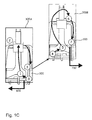
- Fig. 1C is shown in a schematic perspective view of a cascade connection of two refrigeration systems 300 and the fluid circuit shown between the two refrigerators 300, wherein in the first refrigeration system 300A cooling cold 600, for example, water at a temperature of at most 20 ° C, for example, about 15 ° C is discharged and from the second cooling system 300B waste heat 700, that is, heated water is discharged.
- the cooling refrigeration can be used to cool the components 1, that is, for example, the blow molds 101.
- steps 2 and 3 it is shown how a condensation takes place in a first stage at about 32 ° C, wherein between the steps 3 and 4, a cascade connection is realized in which by means of an intermediate circuit between the first stage in the form of the first refrigeration system 300 and the second stage in the form of the second refrigeration system 300, a heat exchange at about 30 ° C takes place.
- an evaporator will increase the water heated to about 30 ° C to 32 ° C, again between steps 5 and 6 within the second refrigeration system 300B
- Fig. 1C cascade circuit described by way of example, a particularly efficient increase in the pressure increase from, for example, 17 mbar initially to 110 mbar, for example.
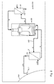
- FIG. 2 is a schematic side view of an embodiment of a container production plant 100 described here comprising the refrigeration system 300 described here and a holding device 400 shown, on the mechanically fixed blow molds 101 are attached.
- the refrigeration system 300 are in direct heat exchange contact via fluid lines 304, which are in direct contact with the blow molds 101, and transport the refrigerated refrigeration 600 to the blow molds 101, so that a particularly efficient cooling by means of the working fluid, which in turn present a water is, is possible.
- a tank A is in heat exchange contact with the ambient air, which additionally transfers heat from the blow molds 101 to the tank A.
- the blow molds 101 which are presently identified as the heat sources increase the water temperature in a tank A from 15 ° initially to 21 ° and this is then introduced into an input of the refrigeration system 300, then to evaporate therein and in the form of water at a temperature of 46 ° C in a second tank B to be initiated.
- the second tank B may be in the form of a heat sink and be, for example, an area disposed outside or on an outer surface of the entire container production line 100.
- such a tank B may be reused for heating rooms using the waste heat 700.
- the reference symbol "W” stands for water and the reference symbol "L” for air.
- the refrigeration system 300 described here can also be completely integrated within a beverage filling machine 200, so that in the Fig. 2 in a particularly simple manner, a very particularly compact and cost-effective method of environmentally friendly cooling of components 1 of a container production plant 100 and / or a beverage filling machine 200 is indicated.
Landscapes
- Engineering & Computer Science (AREA)
- Mechanical Engineering (AREA)
- Manufacturing & Machinery (AREA)
- Physics & Mathematics (AREA)
- Thermal Sciences (AREA)
- General Engineering & Computer Science (AREA)
- Devices That Are Associated With Refrigeration Equipment (AREA)
- Blow-Moulding Or Thermoforming Of Plastics Or The Like (AREA)
- Devices For Dispensing Beverages (AREA)
Applications Claiming Priority (1)
| Application Number | Priority Date | Filing Date | Title |
|---|---|---|---|
| DE201310108366 DE102013108366A1 (de) | 2013-08-02 | 2013-08-02 | Verfahren zur Kühlung von Bauelementen einer Blasformmaschine und/oder einer Getränkeabfüllmaschine |
Publications (1)
| Publication Number | Publication Date |
|---|---|
| EP2853841A1 true EP2853841A1 (fr) | 2015-04-01 |
Family
ID=51300547
Family Applications (1)
| Application Number | Title | Priority Date | Filing Date |
|---|---|---|---|
| EP20140179665 Withdrawn EP2853841A1 (fr) | 2013-08-02 | 2014-08-04 | Procédé de refroidissement de composants d'une machine de formage par soufflage et/ou d'une machine de remplissage de boissons |
Country Status (3)
| Country | Link |
|---|---|
| EP (1) | EP2853841A1 (fr) |
| CN (1) | CN104344585B (fr) |
| DE (1) | DE102013108366A1 (fr) |
Families Citing this family (2)
| Publication number | Priority date | Publication date | Assignee | Title |
|---|---|---|---|---|
| JP6802659B2 (ja) * | 2016-07-29 | 2020-12-16 | 株式会社吉野工業所 | 液体収容容器の製造方法 |
| DE102019210039B4 (de) | 2019-07-08 | 2022-08-11 | Efficient Energy Gmbh | Kühlgerät, Verfahren zum Herstellen eines Kühlgeräts und Transportgerät mit einem Kühlgerät |
Citations (3)
| Publication number | Priority date | Publication date | Assignee | Title |
|---|---|---|---|---|
| DE3827398A1 (de) * | 1988-08-12 | 1990-02-15 | Detlef Schmidt | Kuehlung von werkzeugen und kalibrierungen fuer die thermoplastverarbeitung |
| DD282744A5 (de) * | 1989-04-26 | 1990-09-19 | Hs Fuer Verkehrswesen Friedric | Anordnung zur kaeltebereitstellung in kaltlagerraeumen mit sehr unterschiedlichen waermelasten und temperaturdifferenzen zwischen aussen- und lagerraumlufttemperatur |
| EP2308667A2 (fr) * | 2009-10-12 | 2011-04-13 | Krones AG | Souffleuse dotée d'un refroidissement à efficience énergétique |
Family Cites Families (4)
| Publication number | Priority date | Publication date | Assignee | Title |
|---|---|---|---|---|
| TW340089B (en) * | 1996-05-28 | 1998-09-11 | Idemitsu Petrochemical Co | Method and apparatus for manufacturing hollow formed items |
| CN1223196A (zh) * | 1997-11-14 | 1999-07-21 | 厦门市立精实业有限公司 | 聚对苯二甲酸乙二醇酯耐热瓶(pet)成型方法 |
| DE102011079273A1 (de) * | 2011-07-15 | 2013-01-17 | Krones Aktiengesellschaft | Vorrichtung und Verfahren zum Herstellen von Behältern |
| CN202781798U (zh) * | 2012-08-27 | 2013-03-13 | 杭州特爱科塑料制品有限公司 | 一种吹瓶机冷却装置 |
-
2013
- 2013-08-02 DE DE201310108366 patent/DE102013108366A1/de not_active Withdrawn
-
2014
- 2014-08-01 CN CN201410378473.5A patent/CN104344585B/zh not_active Expired - Fee Related
- 2014-08-04 EP EP20140179665 patent/EP2853841A1/fr not_active Withdrawn
Patent Citations (3)
| Publication number | Priority date | Publication date | Assignee | Title |
|---|---|---|---|---|
| DE3827398A1 (de) * | 1988-08-12 | 1990-02-15 | Detlef Schmidt | Kuehlung von werkzeugen und kalibrierungen fuer die thermoplastverarbeitung |
| DD282744A5 (de) * | 1989-04-26 | 1990-09-19 | Hs Fuer Verkehrswesen Friedric | Anordnung zur kaeltebereitstellung in kaltlagerraeumen mit sehr unterschiedlichen waermelasten und temperaturdifferenzen zwischen aussen- und lagerraumlufttemperatur |
| EP2308667A2 (fr) * | 2009-10-12 | 2011-04-13 | Krones AG | Souffleuse dotée d'un refroidissement à efficience énergétique |
Also Published As
| Publication number | Publication date |
|---|---|
| DE102013108366A1 (de) | 2015-02-05 |
| CN104344585B (zh) | 2017-05-10 |
| CN104344585A (zh) | 2015-02-11 |
Similar Documents
| Publication | Publication Date | Title |
|---|---|---|
| DE69730125T2 (de) | Kältegerät und verfahren zu seiner herstellung | |
| DE102013208369A1 (de) | Vorrichtung mit einer elektronischen Komponente und einer Kältemaschine zum Kühlen der elektronischen Komponente sowie Verfahren zum Kühlen einer elektronischen Komponente | |
| DE102006038061B4 (de) | Kühlkreislaufausbildung mit Ejektor | |
| DE102018002201B4 (de) | Wasser-Lithiumbromid-Absorptionskälteanlage | |
| EP2574865A1 (fr) | Dispositif de stockage d'énergie et procédé de stockage d'énergie | |
| EP0042160A2 (fr) | Procédé et installation pour emmagasiner la chaleur et pour en élever la température | |
| EP3537532B1 (fr) | Procede de refroidissement d'une batterie de traction d'un vehicule a moteur electrique | |
| EP2853841A1 (fr) | Procédé de refroidissement de composants d'une machine de formage par soufflage et/ou d'une machine de remplissage de boissons | |
| DE2754132C2 (de) | Kühlvorrichtung | |
| WO2009080517A1 (fr) | Appareil frigorifique | |
| EP3056694A1 (fr) | Energie réservoir de pression avec pompe de condensat thermique | |
| DE102008002531A1 (de) | Vorrichtung für das Mischen von Flüssigkeit und Dampf sowie Verfahren für das Verdampfen eines Fluids mit der Mischung | |
| DE102011088621B4 (de) | Kraft-Wärme-Maschine und Verfahren zum Herstellen derselben | |
| DE102010012778A1 (de) | Verfahren und Vorrichtung zum Erzeugen kalter gasförmiger oder flüssiger Luft | |
| DE102010045239B4 (de) | Verfahren und Anordnung zum Trocknen einer Transformatorkomponente | |
| DE10162934A1 (de) | Verfahren und Anlage zur solarthermischen Kälteerzeugung | |
| DE102012100645B4 (de) | ORC - Organischer Rankine Zyklus | |
| DE102014000539A1 (de) | Verdampfer | |
| DE4435862C1 (de) | Verfahren und Vorrichtung zum Abkühlen, insbesondere zum Abschrecken, von Werkstücken durch Gase | |
| EP3835688A1 (fr) | Dispositif de refroidissement | |
| AT517761A1 (de) | Vorrichtung zur thermischen Bearbeitung von Kunststoffen | |
| AT12869U1 (de) | Kraft-wärme-maschine und verfahren zum herstellen derselben | |
| DE2153651C3 (de) | Heißgasabtaueinrichtung für Kälteanlagen | |
| DE102021204547B4 (de) | Verdampfer für einen Kühlkreislauf | |
| EP3559579A1 (fr) | Échangeur de chaleur, climatiseur et procédé de condensation et d'évaporation |
Legal Events
| Date | Code | Title | Description |
|---|---|---|---|
| PUAI | Public reference made under article 153(3) epc to a published international application that has entered the european phase |
Free format text: ORIGINAL CODE: 0009012 |
|
| 17P | Request for examination filed |
Effective date: 20140804 |
|
| AK | Designated contracting states |
Kind code of ref document: A1 Designated state(s): AL AT BE BG CH CY CZ DE DK EE ES FI FR GB GR HR HU IE IS IT LI LT LU LV MC MK MT NL NO PL PT RO RS SE SI SK SM TR |
|
| AX | Request for extension of the european patent |
Extension state: BA ME |
|
| R17P | Request for examination filed (corrected) |
Effective date: 20150506 |
|
| RBV | Designated contracting states (corrected) |
Designated state(s): AL AT BE BG CH CY CZ DE DK EE ES FI FR GB GR HR HU IE IS IT LI LT LU LV MC MK MT NL NO PL PT RO RS SE SI SK SM TR |
|
| 17Q | First examination report despatched |
Effective date: 20161216 |
|
| STAA | Information on the status of an ep patent application or granted ep patent |
Free format text: STATUS: THE APPLICATION IS DEEMED TO BE WITHDRAWN |
|
| 18D | Application deemed to be withdrawn |
Effective date: 20190827 |