EP2853864A1 - Flussvolumendetektor - Google Patents
Flussvolumendetektor Download PDFInfo
- Publication number
- EP2853864A1 EP2853864A1 EP12877098.9A EP12877098A EP2853864A1 EP 2853864 A1 EP2853864 A1 EP 2853864A1 EP 12877098 A EP12877098 A EP 12877098A EP 2853864 A1 EP2853864 A1 EP 2853864A1
- Authority
- EP
- European Patent Office
- Prior art keywords
- flow
- flow channels
- volume detector
- groove
- base
- Prior art date
- Legal status (The legal status is an assumption and is not a legal conclusion. Google has not performed a legal analysis and makes no representation as to the accuracy of the status listed.)
- Withdrawn
Links
Images


Classifications
-
- G—PHYSICS
- G01—MEASURING; TESTING
- G01F—MEASURING VOLUME, VOLUME FLOW, MASS FLOW OR LIQUID LEVEL; METERING BY VOLUME
- G01F1/00—Measuring the volume flow or mass flow of fluid or fluent solid material wherein the fluid passes through a meter in a continuous flow
- G01F1/56—Measuring the volume flow or mass flow of fluid or fluent solid material wherein the fluid passes through a meter in a continuous flow by using electric or magnetic effects
- G01F1/58—Measuring the volume flow or mass flow of fluid or fluent solid material wherein the fluid passes through a meter in a continuous flow by using electric or magnetic effects by electromagnetic flowmeters
-
- A—HUMAN NECESSITIES
- A61—MEDICAL OR VETERINARY SCIENCE; HYGIENE
- A61M—DEVICES FOR INTRODUCING MEDIA INTO, OR ONTO, THE BODY; DEVICES FOR TRANSDUCING BODY MEDIA OR FOR TAKING MEDIA FROM THE BODY; DEVICES FOR PRODUCING OR ENDING SLEEP OR STUPOR
- A61M1/00—Suction or pumping devices for medical purposes; Devices for carrying-off, for treatment of, or for carrying-over, body-liquids; Drainage systems
- A61M1/14—Dialysis systems; Artificial kidneys; Blood oxygenators ; Reciprocating systems for treatment of body fluids, e.g. single needle systems for hemofiltration or pheresis
- A61M1/16—Dialysis systems; Artificial kidneys; Blood oxygenators ; Reciprocating systems for treatment of body fluids, e.g. single needle systems for hemofiltration or pheresis with membranes
- A61M1/1621—Constructional aspects thereof
- A61M1/1647—Constructional aspects thereof with flow rate measurement of the dialysis fluid, upstream and downstream of the dialyser
-
- G—PHYSICS
- G01—MEASURING; TESTING
- G01F—MEASURING VOLUME, VOLUME FLOW, MASS FLOW OR LIQUID LEVEL; METERING BY VOLUME
- G01F1/00—Measuring the volume flow or mass flow of fluid or fluent solid material wherein the fluid passes through a meter in a continuous flow
- G01F1/56—Measuring the volume flow or mass flow of fluid or fluent solid material wherein the fluid passes through a meter in a continuous flow by using electric or magnetic effects
- G01F1/58—Measuring the volume flow or mass flow of fluid or fluent solid material wherein the fluid passes through a meter in a continuous flow by using electric or magnetic effects by electromagnetic flowmeters
- G01F1/588—Measuring the volume flow or mass flow of fluid or fluent solid material wherein the fluid passes through a meter in a continuous flow by using electric or magnetic effects by electromagnetic flowmeters combined constructions of electrodes, coils or magnetic circuits, accessories therefor
-
- G—PHYSICS
- G01—MEASURING; TESTING
- G01F—MEASURING VOLUME, VOLUME FLOW, MASS FLOW OR LIQUID LEVEL; METERING BY VOLUME
- G01F15/00—Details of, or accessories for, apparatus of groups G01F1/00 - G01F13/00 insofar as such details or appliances are not adapted to particular types of such apparatus
- G01F15/02—Compensating or correcting for variations in pressure, density or temperature
-
- A—HUMAN NECESSITIES
- A61—MEDICAL OR VETERINARY SCIENCE; HYGIENE
- A61M—DEVICES FOR INTRODUCING MEDIA INTO, OR ONTO, THE BODY; DEVICES FOR TRANSDUCING BODY MEDIA OR FOR TAKING MEDIA FROM THE BODY; DEVICES FOR PRODUCING OR ENDING SLEEP OR STUPOR
- A61M2205/00—General characteristics of the apparatus
- A61M2205/33—Controlling, regulating or measuring
- A61M2205/3317—Electromagnetic, inductive or dielectric measuring means
-
- A—HUMAN NECESSITIES
- A61—MEDICAL OR VETERINARY SCIENCE; HYGIENE
- A61M—DEVICES FOR INTRODUCING MEDIA INTO, OR ONTO, THE BODY; DEVICES FOR TRANSDUCING BODY MEDIA OR FOR TAKING MEDIA FROM THE BODY; DEVICES FOR PRODUCING OR ENDING SLEEP OR STUPOR
- A61M2205/00—General characteristics of the apparatus
- A61M2205/33—Controlling, regulating or measuring
- A61M2205/3324—PH measuring means
-
- A—HUMAN NECESSITIES
- A61—MEDICAL OR VETERINARY SCIENCE; HYGIENE
- A61M—DEVICES FOR INTRODUCING MEDIA INTO, OR ONTO, THE BODY; DEVICES FOR TRANSDUCING BODY MEDIA OR FOR TAKING MEDIA FROM THE BODY; DEVICES FOR PRODUCING OR ENDING SLEEP OR STUPOR
- A61M2205/00—General characteristics of the apparatus
- A61M2205/33—Controlling, regulating or measuring
- A61M2205/3331—Pressure; Flow
- A61M2205/3334—Measuring or controlling the flow rate
-
- A—HUMAN NECESSITIES
- A61—MEDICAL OR VETERINARY SCIENCE; HYGIENE
- A61M—DEVICES FOR INTRODUCING MEDIA INTO, OR ONTO, THE BODY; DEVICES FOR TRANSDUCING BODY MEDIA OR FOR TAKING MEDIA FROM THE BODY; DEVICES FOR PRODUCING OR ENDING SLEEP OR STUPOR
- A61M2205/00—General characteristics of the apparatus
- A61M2205/33—Controlling, regulating or measuring
- A61M2205/3368—Temperature
Definitions
- the present invention relates to a flow volume detector incorporated into a medical artificial dialysis apparatus to detect the flow volume of a dialysate.
- a flow volume detector of this type is disclosed in Patent Document 1.
- the flow volume detector disclosed in this document comprises a synthetic resin base which is attached to/detached from a flow volume measuring device.
- a pair of flow channels, in which a dialysate flows, is formed in the base.
- the base is provided with a detection terminal and an earth terminal in order to detect the flow volumes of the dialysates flowing in the respective flow channels.
- One of the pair of flow channels is connected to an inflow route for conducting a dialysate into a dialyzer of an artificial dialysis apparatus in the state where the flow volume detector is attached to the flow volume measuring device.
- the other flow channel is connected to a return route for returning the dialysate from the dialyzer.
- the respective flow channels are arranged between a pair of magnetic poles of a magnetic circuit including an electromagnetic coil in the flow volume measuring device.
- the pair of flow channels is formed adjacent to each other. Therefore, the base may be deformed if the temperature of a fluid flowing in one of the pair of flow channels becomes high. This is likely to cause a change in sectional area of the other of the pair of flow channels, resulting in the occurrence of an error in the measurement of the flow volume of the dialysate.
- Patent Document 1 Japanese Laid-Open Patent Publication No. 2011-191069
- An object of the present invention is to prevent the temperature of a fluid flowing in one flow channel from affecting the other flow channel, i.e., to provide a flow volume detector which can appropriately hold the sectional areas of the respective flow channels and can also accurately measure the flow volumes of fluids flowing in the respective channels.
- a flow volume detector comprising a base, a plurality of flow channels formed in the base and detecting sections which detect the flow volumes of fluids flowing in the plurality of flow channels.
- a blocking section for blocking heat conduction between the flow channels is provided between the plurality of flow channels.
- the temperature of a fluid flowing in one flow channel may change in some cases. Even in such a case, heat conduction from one flow channel to the other flow channel is blocked by the blocking section provided between the flow channels. Thus, the temperature of the fluid flowing in the one flow channel does not affect the other flow channel. This makes it possible to suitably hold the sectional areas of the respective flow channels and to accurately measure the flow volumes of the fluids flowing in the flow channels.
- the blocking section is preferably configured of a groove formed in the base.
- the groove preferably penetrates from the front face of the base to its back face.
- the detecting sections are preferably arranged in the center part in the longitudinal direction of the groove.
- orifice-shaped measurement flow generating sections are formed in the flow channels, and the detecting sections are arranged in the measurement flow generating sections.
- inclined parts are formed in both end parts in a direction in which fluids flow, and the inclined parts are formed such that the flow channels become narrower as the flow channels go toward the measurement flow generating sections.
- the detecting sections have terminals arranged in end parts on both sides in the width direction of the measurement flow generating sections, and the terminals preferably detect electromotive forces developed by flowing fluids.
- the plurality of flow channels are configured by a pair of flow channels, and the pair of flow channels are respectively arranged in the same plane on both sides of the groove and sandwiching the groove.
- the temperature of a fluid flowing in one flow channel is prevented from affecting the other channel, thereby making it possible to suitably hold the sectional areas of the respective flow channels and to accurately measure the flow volumes of the fluids flowing in the flow channels.
- an artificial dialysis apparatus 21 comprises a dialyzer 22.
- a dialyzer 22 Upon operation of a pump 23, blood 24 containing waste matter 241 derived from the body of a patient is introduced into the dialyzer 22 via a blood circulation route 25.
- the waste matter 241 in the blood is separated and taken in a dialysate 26 as a fluid.
- the clean blood 24 after filtration is returned to the patient's body.
- the artificial dialysis apparatus 21 further comprises a flow volume measuring device 27.
- the flow volume measuring device 27 is provided with a magnetic circuit 28 comprising an electromagnetic coil 281 and a pair of magnetic poles 282 and a signal processing circuit 29 for processing a measurement signal. An alternating current is supplied to the electromagnetic coil 281.
- a disposable type flow volume detector 30 is attached to the flow volume measuring device 27 in order to measure the flow volume of a dialysate 26.
- the flow volume detector 30 is configured to be attachable to/detachable from the flow volume measuring device 27.
- the flow volume detector 30 is provided with a pair of flow channels 33, 34.
- the flow channels 33, 34 are connected to an inflow route 31 and a return route 32, respectively, for the dialysate 26 with respect to the dialyzer 22.
- Both the flow channels 33, 34 are arranged between both the magnetic poles 282 of the magnetic circuit 28 in the state where the flow volume detector 30 is attached to the flow volume measuring device 27.
- the dialysate 26 is allowed to flow into the dialyzer 22 via the inflow route 31 and flow channel 33 from a supply tank 36.
- the dialysate 26 containing the waste matter 241 separated by the dialyzer 22 is returned to a drain tank 37 via the return route 32 and flow channel 34.
- the flow volumes of the dialysates 26 flowing in the respective flow channels 33, 34 are respectively measured by the flow volume detector 30.
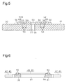
- the flow volume detector 30 comprises a base 41 made of a transparent synthetic resin such as a polypropylene resin.
- the base 41 is formed into a rectangular plate form. From both end faces of the base 41, a pair of connection pipes 42, 43 is respectively protruded.
- the respective connection pipes 42, 43 are connected to the middle of the inflow route 31 and return route 32.
- concave parts 46, 47 which are in communication with passages 44, 45 within the respective connection pipes 42, 43, are formed in both end parts of the base 41.
- the passages 44, 45 are connected to the concave parts 46, 47, respectively, in positions slightly higher than the bottom faces of the concave parts 46, 47.
- Groove parts 461, 471 are formed at sites near to the center of the base 41 in the concave parts 46, 47.
- the groove parts 461, 471 are shallower than the concave parts 46, 47 and are arranged in positions higher than the passages 44, 45.
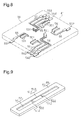
- lid plates 48, 49 are adhered or welded onto the upper face of the base 41.
- the lid plates 48, 49 are formed of a transparent synthetic resin such as a polypropylene resin.
- the respective lid plates 48, 49 are positioned in predetermined positions on the base 41 by a plurality of positioning pins 50.
- measurement groove parts 51, 52 which are in communication with the concave parts 46, 47 and groove parts 461, 471, are formed on the back face of the respective lid plates 48, 49.
- Convex parts 511, 521 are formed in the center parts in the longitudinal direction of the respective measurement groove parts 51, 52.
- Inclined parts 512, 522 are formed in both end parts of the concave parts 511, 521.
- the flow channel 33 is configured of the passage 44 of the connection pipe 42, the concave part 46, the groove part 461 and the measurement groove part 51 of the lid plate 48 in a state where the lid plates 48, 49 are fixed on the base 41.
- the flow channel 34 is configured of the passage 45 of the connection pipe 43, the concave part 47, the groove part 471 and the measurement groove part 52 of the lid plate 49.
- Orifice-shaped measurement flow generating sections 331, 341 are formed between the convex parts 511, 521 of the respective lid plates 48, 49 and the upper face of the base 41.
- the respective measurement flow generating sections 331, 341 have passage sectional areas suitable to generate the measurement flows of the dialysates 26 in the respective flow channels 33, 34.
- a pair of detection bus bars 53 and a pair of detection bus bars 54 are embedded within the base 41.
- a detection terminal 531 as a detecting section, which is exposed within the measurement flow generating section 331, is formed in the first end of the respective detection bus bars 53.
- a detection terminal 541 as a detecting section, which is exposed within the measurement flow generating section 341, is formed in the first end of the respective detection bus bars 54.
- the detection terminals 531, 541 are arranged opposite to each other in end parts in the width direction of the measurement flow generating sections 331, 341. As shown in Figs.
- connection terminals 532 which are exposed to the end face of the base 41, are respectively formed in the second end parts of the respective detection bus bars 53.
- the connection terminals 532, 542 are connected to a signal processing circuit 29 of the flow volume measuring device 27.
- an earth bus bar 55 and an earth bus bar 56 are embedded.
- Earth terminals 551, 561, which are exposed within the groove parts 461, 471, are respectively formed in the first end parts of the respective earth bus bars 55, 56.
- Connection terminals 552, 562, which are exposed to the end face of the base 41, are respectively formed in the second end parts of the respective earth bus bars 55, 56.
- the connection terminals 552, 562 are connected to the signal processing circuit 29.
- a blocking section 57 is provided in the center between both the flow channels 33, 34 in the base 41.
- the blocking section 57 blocks heat conduction from one of the pair of flow channels 33, 34 through the base 41 to the other flow channel.
- the blocking section 57 extends along the flow channels 33, 34 between both the flow channels 33, 34.
- the blocking section 57 is configured of a through groove 58 penetrating from the front face of the base 41 toward its back face. Both the flow channels 33, 34 are arranged in the same plane on both sides sandwiching the through groove 58.
- the detection terminals 531, 541 are arranged in the center part in the longitudinal direction of the through groove 58.
- the flow volume detector 30 is attached to the flow volume measuring device 27 when the artificial dialysis apparatus 21 is used.
- the flow channel 33 is connected to the middle of the inflow route 31, and the flow channel 34 is connected to the middle of the return route 32.
- the measurement flow generating sections 331, 341 of the respective flow channels 33, 34 shown in Fig. 4 are arranged between the pair of magnetic poles 282 of the magnetic circuit 28.
- the blood 24 derived from a patient is introduced into the dialyzer 22 via the blood circulation route 25 by actuation of the pump 23.
- the dialysate 26 within the supply tank 36 is allowed to flow into the dialyzer 22 via the inflow route 31 and flow channel 33 by actuation of the pump 35. Therefore, the blood 24 is filtered with the dialyzer 22, and, simultaneously, the waste matter 241 in the blood 24 is separated and transferred into the dialysate 26.
- the cleaned blood 24 is returned to the patient via the blood circulation route 25.
- the dialysate 26 containing the waste matter 241 is recovered to a drain tank 37 via the return route 32 and flow channel 34.
- an alternating field is generated by an alternating current in the magnetic circuit 28.
- the magnetic flux penetrates the measurement flow generating sections 331, 341 of the respective flow channels 33, 34. Therefore, electromotive forces corresponding to the flow rates of the dialysates 26 flowing in the measurement flow generating sections 331, 341 are developed.
- the electromotive forces are output as detection signals from the detection terminals 531, 541 of the respective detection bus bars 53, 54 to the signal processing circuit 29.
- the detection signals are output at a level set according to the earth potential from the earth bus bars 55, 56.
- the flow volumes per unit time of the dialysates 26 flowing in the respective flow channels 33, 34 are respectively measured from the detection signal based on the flow rates of the dialysates 26 and the sectional areas of the measurement flow generating sections 331, 341.
- the amount of the waste matter 241 separated from the blood 24 is calculated based on the difference between the flow volumes of the dialysates 26 flowing in both the flow channels 33, 34.
- the base 41 made of a synthetic resin and the lid plate 48 may expand or contract. This is likely to cause a change in sectional area of the measurement flow generating sections 331, 341 in the other of the flow channels 34, 33, resulting in the occurrence of an error in the measurement of the flow volume.
- the through groove 58 is formed as the blocking section 57 for substantially blocking heat conduction between both the flow channels 33, 34 on the base 41. Therefore, the temperature of the dialysate 26 flowing in one of the flow channels 33, 34, even if changed, hardly affects the other flow channel by virtue of the through groove 58.
- the first embodiment can provide the following advantageous effects.
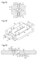
- a through groove 58 as a blocking section 57 is divided into two parts in the longitudinal direction, as shown in Fig. 10 .
- the second embodiment can provide the following advantageous effect.
- a blocking section 57 is configured of a concave groove 59 formed in the upper face of the base 41.
- the concave groove 59 has a bottom wall.
- the concave groove 59 are provided between both flow channels 33, 34 and extend along the flow channels 33,34.
- the third embodiment can provide the following advantageous effect. (9) Since the concave groove 59 has a bottom wall, it is possible to suppress the deformation of the base 41 as a whole and to obtain the reinforcing effect of the base 41.
- a pair of flow channels 33, 34 is formed such that they are spaced apart in the thickness direction of a base 41 and overlap each other.
- a through groove 58 as a blocking section 57 is provided between the flow channels 33, 34. The through groove 58 penetrates from one of both ends of the base 41 to the other.
- the fourth embodiment can provide the following advantageous effect.
- one lid plate 60 is employed in place of the pair of lid plates 48, 49 in the respective embodiments described above.
- a through groove 61 as a blocking section which penetrates from the front face of the lid plate 60 toward its back face is formed in the center part of the lid plate 60.
- the through groove 61 is formed in a position corresponding to the through groove 58 of the base 41.
- the through groove 61 has almost the same width and length as those of the through groove 58.
- the fourth embodiment can provide the following advantageous effect.
- one of the pair of lid plates 48, 49 is attached to a surface of a base 41 opposite to another surface thereof to which the other lid plate is attached. Therefore, also for a pair of flow channels 33, 34 and detection bus bars 53, 54, one of the flow channels or detection bus bars is provided on a surface of the base 41 opposite to another surface thereof on which the other flow channel or detection bus bar is provided.
- the sixth embodiment can provide the following advantageous effect. (12) One of the pair of flow channels 33, 34 is provided on a surface of the base 41 opposite to another surface thereof on which the other flow channel is provided. According to this configuration, it is possible to further suppress the temperature of the fluid flowing in one of the pair of flow channels 33, 34 from affecting the other flow channel because of a long distance between the flow channels 33, 34.
- a heat insulating material such as expanded polystyrene may be packed within the through groove 58 or concave groove 59. That is, the blocking section 57 may be configured of the through groove 58 or concave groove 59 and the heat insulating material.
- a plurality of small holes may be linearly and continuously formed to configure the blocking section 57.
- the flow volume detector according to the present invention may be used in fields other than artificial dialysis.
Landscapes
- Health & Medical Sciences (AREA)
- Physics & Mathematics (AREA)
- Fluid Mechanics (AREA)
- Heart & Thoracic Surgery (AREA)
- Urology & Nephrology (AREA)
- General Physics & Mathematics (AREA)
- Electromagnetism (AREA)
- Anesthesiology (AREA)
- Vascular Medicine (AREA)
- Engineering & Computer Science (AREA)
- Emergency Medicine (AREA)
- Biomedical Technology (AREA)
- Hematology (AREA)
- Life Sciences & Earth Sciences (AREA)
- Animal Behavior & Ethology (AREA)
- General Health & Medical Sciences (AREA)
- Public Health (AREA)
- Veterinary Medicine (AREA)
- External Artificial Organs (AREA)
- Measuring Volume Flow (AREA)
Applications Claiming Priority (1)
| Application Number | Priority Date | Filing Date | Title |
|---|---|---|---|
| PCT/JP2012/062912 WO2013175547A1 (ja) | 2012-05-21 | 2012-05-21 | 流量検出器 |
Publications (2)
| Publication Number | Publication Date |
|---|---|
| EP2853864A1 true EP2853864A1 (de) | 2015-04-01 |
| EP2853864A4 EP2853864A4 (de) | 2016-07-20 |
Family
ID=49623280
Family Applications (1)
| Application Number | Title | Priority Date | Filing Date |
|---|---|---|---|
| EP12877098.9A Withdrawn EP2853864A4 (de) | 2012-05-21 | 2012-05-21 | Flussvolumendetektor |
Country Status (5)
| Country | Link |
|---|---|
| US (1) | US9752906B2 (de) |
| EP (1) | EP2853864A4 (de) |
| JP (1) | JP6081454B2 (de) |
| CN (1) | CN104303022B (de) |
| WO (1) | WO2013175547A1 (de) |
Cited By (1)
| Publication number | Priority date | Publication date | Assignee | Title |
|---|---|---|---|---|
| EP3274014B1 (de) * | 2015-03-24 | 2024-04-24 | Fresenius Medical Care Deutschland GmbH | Temperaturstörungsunabhängige bilanzierungseinrichtung |
Families Citing this family (7)
| Publication number | Priority date | Publication date | Assignee | Title |
|---|---|---|---|---|
| DE102014009444A1 (de) * | 2014-06-25 | 2015-12-31 | Fresenius Medical Care Deutschland Gmbh | Flussmesser und Kassettenmodul für einen Flussmesser |
| US10172989B2 (en) * | 2014-09-12 | 2019-01-08 | Easydial Inc. | Portable hemodialysis machine and disposable cartridge with blood leak sensor |
| JP6395568B2 (ja) * | 2014-11-13 | 2018-09-26 | 愛知時計電機株式会社 | 流量計測器及び電磁流量計 |
| DE102015001406B3 (de) * | 2015-02-04 | 2016-07-14 | Fresenius Medical Care Deutschland Gmbh | Kassettenmodul für einen Differenzflussmesser und Differenzflussmesser |
| CN109707932B (zh) * | 2018-12-27 | 2020-09-04 | 宁波安创电子科技有限公司 | 高效高精度流量检测设备 |
| DE102020102485A1 (de) | 2020-01-31 | 2021-08-05 | Fresenius Medical Care Deutschland Gmbh | Flusssensor und Verfahren zum Messen eines Flusses |
| CN112197823A (zh) * | 2020-08-21 | 2021-01-08 | 蚌埠恒远传感器科技有限公司 | 智能电磁流量传感器 |
Family Cites Families (13)
| Publication number | Priority date | Publication date | Assignee | Title |
|---|---|---|---|---|
| YU42759B (en) * | 1982-03-18 | 1988-12-31 | Ljubljana Avtomontaza | Heat power gauge |
| JPS6015629U (ja) * | 1983-07-13 | 1985-02-02 | 横河電機株式会社 | 電磁流量計発信器 |
| US4542650A (en) * | 1983-08-26 | 1985-09-24 | Innovus | Thermal mass flow meter |
| JP2894878B2 (ja) * | 1991-09-27 | 1999-05-24 | 株式会社東芝 | 電磁流量計 |
| FR2735571B1 (fr) * | 1995-06-15 | 1997-08-29 | Schlumberger Services Petrol | Debitmetre a venturi pour mesure dans une veine d'ecoulement d'un fluide |
| JP2004093392A (ja) * | 2002-08-30 | 2004-03-25 | Yazaki Corp | 電子化ガスメータの脈動吸収構造 |
| US7403704B2 (en) | 2004-08-06 | 2008-07-22 | Terumo Cardiovascular Systems Corporation | Dual heating device and method |
| US20080103428A1 (en) * | 2004-09-09 | 2008-05-01 | Delaronde-Wilton Glen James Wi | Apheresis Tubing Set |
| JPWO2008132956A1 (ja) * | 2007-04-24 | 2010-07-22 | コニカミノルタエムジー株式会社 | 流量センサ |
| US7631562B1 (en) * | 2008-08-19 | 2009-12-15 | Honeywell International Inc. | Mass-flow sensor with a molded flow restrictor |
| US7571655B1 (en) * | 2008-11-28 | 2009-08-11 | Murray F Feller | Magnetic flow meter with buffering electrodes |
| JP5467576B2 (ja) * | 2010-03-11 | 2014-04-09 | 愛知時計電機株式会社 | 流量計測ピース及び電磁流量計 |
| US8756990B2 (en) * | 2010-04-09 | 2014-06-24 | Honeywell International Inc. | Molded flow restrictor |
-
2012
- 2012-05-21 WO PCT/JP2012/062912 patent/WO2013175547A1/ja not_active Ceased
- 2012-05-21 EP EP12877098.9A patent/EP2853864A4/de not_active Withdrawn
- 2012-05-21 JP JP2014516532A patent/JP6081454B2/ja not_active Expired - Fee Related
- 2012-05-21 CN CN201280073265.3A patent/CN104303022B/zh not_active Expired - Fee Related
- 2012-05-21 US US14/400,730 patent/US9752906B2/en not_active Expired - Fee Related
Cited By (1)
| Publication number | Priority date | Publication date | Assignee | Title |
|---|---|---|---|---|
| EP3274014B1 (de) * | 2015-03-24 | 2024-04-24 | Fresenius Medical Care Deutschland GmbH | Temperaturstörungsunabhängige bilanzierungseinrichtung |
Also Published As
| Publication number | Publication date |
|---|---|
| CN104303022B (zh) | 2017-07-11 |
| HK1202615A1 (zh) | 2015-10-02 |
| JPWO2013175547A1 (ja) | 2016-01-12 |
| JP6081454B2 (ja) | 2017-02-15 |
| US20150135848A1 (en) | 2015-05-21 |
| EP2853864A4 (de) | 2016-07-20 |
| WO2013175547A1 (ja) | 2013-11-28 |
| US9752906B2 (en) | 2017-09-05 |
| CN104303022A (zh) | 2015-01-21 |
Similar Documents
| Publication | Publication Date | Title |
|---|---|---|
| US9752906B2 (en) | Flow volume detector | |
| RU2499228C2 (ru) | Магнитно-индуктивный расходомер | |
| EP3435040B1 (de) | Elektromagnetischer durchflusssensor | |
| ES2776477T3 (es) | Detector de conductividad para líquidos | |
| CA2009133A1 (en) | Fluid flow meters | |
| EP3254066B1 (de) | Flussmesser und kassettenmodul für einen flussmesser | |
| AU2016381942B2 (en) | Electrical sensor for fluids | |
| CN106461432A (zh) | 流量测量器和用于流量测量器的盒模块 | |
| CN110161294A (zh) | 电流传感器 | |
| US10617809B2 (en) | Electrical sensor for fluids | |
| CN104246451B (zh) | 流量计、测量管及流量计的制造方法 | |
| WO2018138518A1 (en) | Electromagnetic flow sensor | |
| HK1202615B (en) | Flow volume detector | |
| CN111330659B (zh) | 基于电学信号的微流控芯片和血细胞分析装置及方法 | |
| JP2002277380A (ja) | マイクロ血球カウンタ | |
| JP2017133918A (ja) | 体液粘性測定装置 | |
| KR101308116B1 (ko) | 적혈구 변형률 측정 장치 | |
| WO2018046896A1 (en) | Spring-loaded liquid conductivity measurement pin and corresponding manufacturing method | |
| JP7003640B2 (ja) | 粒子検出装置及び粒子検出方法 | |
| CN113125831A (zh) | 具有双厚度导体的电流传感器 | |
| Fristedt et al. | Motionally Induced Electrical Field from a Two-Layer Channel-Flow of Rectangular or Elliptical Cross-Section; a Possibility to Resolve Baroclinic Flow Features? | |
| CA2178468C (en) | Differential conductivity hemodynamic monitor | |
| Yeste Lozano et al. | A novel strategy to monitor microfluidic in-vitro blood-brain barrier models using impedance spectroscopy | |
| HK1167178A (en) | Electromagnetic flowmeter |
Legal Events
| Date | Code | Title | Description |
|---|---|---|---|
| PUAI | Public reference made under article 153(3) epc to a published international application that has entered the european phase |
Free format text: ORIGINAL CODE: 0009012 |
|
| 17P | Request for examination filed |
Effective date: 20141222 |
|
| AK | Designated contracting states |
Kind code of ref document: A1 Designated state(s): AL AT BE BG CH CY CZ DE DK EE ES FI FR GB GR HR HU IE IS IT LI LT LU LV MC MK MT NL NO PL PT RO RS SE SI SK SM TR |
|
| AX | Request for extension of the european patent |
Extension state: BA ME |
|
| DAX | Request for extension of the european patent (deleted) | ||
| RA4 | Supplementary search report drawn up and despatched (corrected) |
Effective date: 20160617 |
|
| RIC1 | Information provided on ipc code assigned before grant |
Ipc: A61M 1/16 20060101ALI20160613BHEP Ipc: G01F 15/02 20060101ALI20160613BHEP Ipc: A61M 1/14 20060101ALI20160613BHEP Ipc: G01F 1/58 20060101AFI20160613BHEP |
|
| STAA | Information on the status of an ep patent application or granted ep patent |
Free format text: STATUS: EXAMINATION IS IN PROGRESS |
|
| 17Q | First examination report despatched |
Effective date: 20210520 |
|
| GRAP | Despatch of communication of intention to grant a patent |
Free format text: ORIGINAL CODE: EPIDOSNIGR1 |
|
| STAA | Information on the status of an ep patent application or granted ep patent |
Free format text: STATUS: GRANT OF PATENT IS INTENDED |
|
| INTG | Intention to grant announced |
Effective date: 20230509 |
|
| STAA | Information on the status of an ep patent application or granted ep patent |
Free format text: STATUS: THE APPLICATION IS DEEMED TO BE WITHDRAWN |
|
| 18D | Application deemed to be withdrawn |
Effective date: 20230920 |