EP2853877A2 - Système et procédé de mise à disposition de données de diagnostic pour un porte-couteaux d'un granulateur de plastique - Google Patents
Système et procédé de mise à disposition de données de diagnostic pour un porte-couteaux d'un granulateur de plastique Download PDFInfo
- Publication number
- EP2853877A2 EP2853877A2 EP20140182767 EP14182767A EP2853877A2 EP 2853877 A2 EP2853877 A2 EP 2853877A2 EP 20140182767 EP20140182767 EP 20140182767 EP 14182767 A EP14182767 A EP 14182767A EP 2853877 A2 EP2853877 A2 EP 2853877A2
- Authority
- EP
- European Patent Office
- Prior art keywords
- knife roller
- diagnostic data
- knife
- bearing
- vibrations
- Prior art date
- Legal status (The legal status is an assumption and is not a legal conclusion. Google has not performed a legal analysis and makes no representation as to the accuracy of the status listed.)
- Granted
Links
- 238000000034 method Methods 0.000 title claims abstract description 20
- 238000005096 rolling process Methods 0.000 title description 2
- 238000012423 maintenance Methods 0.000 claims abstract description 18
- 238000012545 processing Methods 0.000 claims abstract description 18
- 238000001514 detection method Methods 0.000 claims description 8
- 230000010355 oscillation Effects 0.000 claims description 5
- 238000001125 extrusion Methods 0.000 claims description 2
- 238000005259 measurement Methods 0.000 description 27
- 238000011156 evaluation Methods 0.000 description 2
- 239000008187 granular material Substances 0.000 description 2
- 230000001960 triggered effect Effects 0.000 description 2
- 230000001133 acceleration Effects 0.000 description 1
- 238000004140 cleaning Methods 0.000 description 1
- 238000013500 data storage Methods 0.000 description 1
- 230000002950 deficient Effects 0.000 description 1
- 230000001419 dependent effect Effects 0.000 description 1
- 238000011161 development Methods 0.000 description 1
- 230000018109 developmental process Effects 0.000 description 1
- 230000006870 function Effects 0.000 description 1
- 239000000463 material Substances 0.000 description 1
- 238000000691 measurement method Methods 0.000 description 1
- 238000005070 sampling Methods 0.000 description 1
- 238000010008 shearing Methods 0.000 description 1
- 239000013589 supplement Substances 0.000 description 1
- 230000009466 transformation Effects 0.000 description 1
Images
Classifications
-
- B—PERFORMING OPERATIONS; TRANSPORTING
- B29—WORKING OF PLASTICS; WORKING OF SUBSTANCES IN A PLASTIC STATE IN GENERAL
- B29B—PREPARATION OR PRETREATMENT OF THE MATERIAL TO BE SHAPED; MAKING GRANULES OR PREFORMS; RECOVERY OF PLASTICS OR OTHER CONSTITUENTS OF WASTE MATERIAL CONTAINING PLASTICS
- B29B9/00—Making granules
- B29B9/02—Making granules by dividing preformed material
- B29B9/06—Making granules by dividing preformed material in the form of filamentary material, e.g. combined with extrusion
-
- G—PHYSICS
- G01—MEASURING; TESTING
- G01M—TESTING STATIC OR DYNAMIC BALANCE OF MACHINES OR STRUCTURES; TESTING OF STRUCTURES OR APPARATUS, NOT OTHERWISE PROVIDED FOR
- G01M13/00—Testing of machine parts
- G01M13/04—Bearings
- G01M13/045—Acoustic or vibration analysis
Definitions
- the invention relates to a method and a system for providing diagnostic data to a knife roll device of a plastic strand pelletizer.
- the system comprises a knife roller device with a knife roller and at least one knife roller bearing.
- a granulator for strand materials which comprises a rotating shear blade roll and a lower and upper draw-in roll.
- the shearing cutter roller and / or the lower feed roller are movable.
- the maintenance-related expansion of the shear blade roller for example, for the regular regrinding of the blades, easier to implement.
- the knife roller device as a whole, that is, including the outer bearing shells of the knife roller bearing, lifted out of the granulator. This is done either for maintenance purposes of the knife roller, if it must be reground or repaired, or in the case of bearing damage for the purpose of replacing the defective bearing.
- the maintenance of the Kunststoffstranggranuliervoriques is usually carried out externally by the manufacturer of the device or by a service authorized by this service.
- the object of the present invention is to optimize the maintenance of plastic strand pelletizers.
- Essential for the present invention is first that at least one sensor is provided to detect vibrations of the knife roller device.
- the detected vibrations are characteristic of the state of wear of the at least one knife roller bearing of the knife roller device.
- the detected vibration signals are then stored by means of a memory device in the form of diagnostic data, so that they are available after a removal of the knife roller device from the plastic strand pelletizer during maintenance.
- a service service for knife roller devices is therefore not only the knife roller device nachzuschleifende with an unknown state of wear of the knife roller bearings available, but also the stored diagnostic data that provide indirect information about the state of wear of the bearing.
- the stored diagnostic data are preferably initially present in a form that substantially corresponds to a transformation of the detected vibration signals for the purpose of mere storage for later evaluation.
- the evaluation of the diagnostic data then takes place only by a maintenance service, which processes the diagnostic data by means of an analysis device in order to determine the state of wear of the bearings.
- the storage device is part of the knife roller device. This is advantageous in that the maintenance service receives the stored diagnostic data together with the associated knife roller device.
- the maintenance service may obtain access to the diagnostic data via a machine interface with network connection or via an external data store on which the diagnostic data is stored and which is also handed over for maintenance.
- the diagnostic data already evaluated can be stored in the memory device so that the wear state of the bearings can be determined directly by reading the memory device.
- the measurements required for providing the diagnostic data take place at idle of the knife roller and are preferably carried out before or after the regular operation of the plastic strand pelletizer, ie in particular in the course of the switch-on or the switch-off of the knife roller device.
- the measurements take place under defined conditions, which in particular the measurement duration, the measurement speed and / or the sampling frequency of the measured signal may relate.
- the system preferably comprises a control device for this purpose. This is for example set up to initiate the detection of the vibrations by the sensor when idling the knife roller, in particular at idle at one or more defined measuring speeds or measuring speed ranges of the knife roller and / or in the course of the switch-on or the switch-off of the knife roller device.
- reference diagnostic data of identically constructed and fully functional knife roller bearings are determined under the same defined conditions.
- the analysis device is able to use this reference diagnostic data to determine differences by comparing the diagnostic data from currently used knife roller bearings with the reference diagnostic data, which provide information about the state of wear of the bearing.
- a variety of diagnostic data of knife roller bearings are detected with different, but known wear conditions and compared with the reference diagnostic data and assigned characteristic differences to the respective state of wear. Based on this data, the analyzer is able to provide accurate information about the wear condition of bearings based on existing diagnostic data.
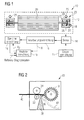
- FIG. 1 Shown in FIG. 1 is a system 10 for providing diagnostic data to a knife roll apparatus of a plastic extrusion granulator 30 according to a preferred embodiment.
- the system 10 comprises a knife roller device 12, a sensor 14 for detecting vibrations, a control device 11 which is arranged to initiate the detection of the vibrations by the sensor when the knife roller is idling, a processing device 16 which is suitable for the sensor 14 detected vibration signals in diagnostic data, and a memory device 18, which is adapted to store the converted by the processing means 16 diagnostic data.
- the knife roller device 12 comprises a knife roller 20 which is arranged on a shaft 22.
- the shaft 22 is supported at both ends in a knife roller bearing 23.
- the shaft 22 is supported at only one end in a knife roller bearing 23.
- the knife roller bearing 23 includes a bearing housing 24 with a radial bearing 26.
- the knife roller bearing 23 additionally includes a thrust bearing 28.
- an eyebolt 5 is disposed on the bearing housing 24, at which the knife roller device 12 can be pulled out of the plastic strand pelletizer 30.
- the sensor 14 is arranged such that it is capable of detecting vibrations of the associated knife roller bearing 23 when the knife roller 20 rotates. In some embodiments, the sensor 14 is disposed proximate the associated knife roller bearing 23. In some embodiments, the sensor 14 is located outside of the bearing housing 24 and thus is not part of the knife roll apparatus 12. In other embodiments, the sensor 14 is disposed in the bearing housing 24 and thus part of the knife roll apparatus 12. In some embodiments, the sensor 14 is directly attached to the associated knife roll bearing 23 attached.
- each radial or thrust bearing 26, 28 of the knife roller bearing 23 is assigned a separate sensor 14, which receives the vibrations generated by the respective bearing.
- only the radial bearing 26 or only the thrust bearing 28 is assigned a separate sensor 14, while the other bearings are not monitored directly by associated sensors.
- a common sensor 14 are assigned, with an isolated view of the different bearings 26, 28 is possible because of their different vibration characteristics in spite of common measurement by the single signals to be allocated signal components are filtered out of the total signal.
- the senor 14 is a vibration sensor that may have a temperature resistance of at least 100 ° C.
- the at least one sensor 14 is, for example, a microphone, an acceleration sensor, an LVDT or a vibrometer.
- the sensor 14 detects the vibrations on the sensor surface and converts them into vibration signals, which are preferably present as electrical signals.
- the sensor 14 is connected to the processing device 16, which processes the vibration signals.
- the electrical signals of the sensor 14 are converted to digital signals by means of an analog-to-digital converter, which are available as diagnostic data for further processing.
- the function of the processing device 16 thus comprises the processing of the sensor signal for the purpose of storage in a memory device 18.
- the memory device 18, as shown is part of Knife roller device 12. Additionally or optionally only alternatively, the processing device 16 may be part of the knife roller device 12.
- the processing device 16 and the memory device 18 can be integrated in a microchip as CPU and EEPROM.
- the system 10 is configured to detect idle vibrations of the knife roller 20 to keep the measurement of operational disturbances free.
- the vibrations are detected at a defined measuring speed, for example 500 revolutions per minute.
- a predetermined measuring speed range is run through, in which the detection of the vibrations takes place, for example in the range of 400 to 600 revolutions per minute. In still other embodiments, the detection of the vibrations takes place during different measuring speeds or measuring speed ranges. In some embodiments, measurement profiles are used in which a given measurement speed is used at certain times during the measurement.
- the measuring speed or the measuring speed range is below an operating speed of the knife roller 20.
- the measurement can be carried out regularly before reaching and / or after leaving the operating speed.
- the measuring speed may in some embodiments be a predetermined proportion of the operating speed, for example 50%. In other embodiments, the measuring speed but also correspond to the operating speed. It is also not excluded that the measuring speed is above the operating speed. This may also be expedient depending on the expected vibration characteristics.
- the operating speed is 300 to 2,500 revolutions per minute, for example, 1,000 revolutions per minute.
- the detection of the oscillations takes place during a switch-on operation of the knife roller device 12, wherein the actual rotational speed when reaching the one or more measuring speeds or measuring rotational speed ranges is optionally maintained at the respective measuring rotational speed and / or the measuring rotational speed ranges are traversed, so that the sensor 14 Can detect vibrations.
- the knife roller assembly 12 changes the current speed from the measuring speed to the desired operating speed. This embodiment is particularly advantageous when the measuring speed is below the operating speed, because thereby the measurement can be made during the startup of the machine, the startup is extended substantially only by the measurement period.
- the detection of the vibrations takes place during a turn-off operation of the knife roll device 12.
- the current speed is changed from the operating speed to the measuring speed.
- the current rotational speed is maintained at the respective measuring rotational speed when the one or more measuring rotational speeds or measuring rotational speed ranges are reached and / or the measuring rotational speed ranges are traversed so that the sensor 14 can detect the oscillations.
- the knife roller device 12 continues to ramp down. This embodiment is particularly advantageous when the measuring speed is below the operating speed, because thereby the measurement can be done during the shutdown of the speed, the shutdown is extended substantially only by the measurement period.
- a measuring operation is performed both during a power-on operation of the knife roller device 12 and during a turn-off operation.
- the diagnostic data is evaluated in an analyzer 19.
- the analysis device 19 compares the present diagnostic data with diagnostic data of similar, functional knife roller devices 12, which serve as reference. Depending on the size of the difference between the present diagnostic data and the reference diagnostic data, the analysis device 19 may indicate a state of wear of the associated bearing 26, 28.
- the analyzer 19 is part of the system 10.
- the analysis device 19 determines in some embodiments, the state of wear of the total of the plurality of individual bearings 26, 28, without making an assignment, such as the state of wear of each of the plurality of individual bearings 26, 28 is given. Again, in other embodiments, based on the diagnostic data, the analyzer 19 evaluates the wear condition of the individual bearings 26, 28 due to the different vibration characteristics of the individual bearings.
- the analyzer 19 is connected to the processing device 16 and is in some embodiments part of the knife-rolling device 12. In other embodiments, the analyzer 19 is part of the processing device 16. In yet other embodiments, the analyzer 19 is part of a maintenance system that includes the diagnostic data regardless of the knife roller device 12, the system 10 or the plastic strand pelletizer 30 can evaluate.
- the memory device 18 is galvanically or wirelessly connected to the processing device 16 and stores the diagnostic data provided by the processing device 16, which subsequently or even much later, namely, for example, after removal of the knife roller device, transmitted to the analysis device 19 become.
- the memory device 18 also stores the diagnostic data evaluated by an optional analyzer 19 (see arrow X 2 in FIG Fig. 1 ).
- the memory device 18 stores the diagnostic data evaluated by the analyzer 19 without separately storing the underlying diagnostic data (see arrows X 1 and X 2 in FIG Fig. 1 ).
- the memory device 18 may in some embodiments also store the time of measurement and / or identification of the measurement method used, so that a history of the diagnostic data can be retrieved.
- the memory device 18 may, in some embodiments, have a machine interface to an external data store and thereby provide the diagnostic data to be stored at the machine interface.
- the machine interface of the storage device 18 may be, for example, a USB interface, a network interface (e.g., Ethernet), or a data storage interface (e.g., Serial ATA).
- the machine interface of the memory device 18 may replace an internal data memory of the memory device 18, so that during a measurement process, a data memory must be connected to the machine interface of the memory device 18.
- the machine interface of the memory device 18 may supplement the internal data memory so that diagnostic data may be transferred from the internal data memory to the external data memory connected to the machine interface.
- the processing device 16 and / or the analysis device 19 has a machine interface, which are provided for the configuration of these devices, in particular for importing reference diagnostic data or for defining measurement profiles in which measurement duration, measurement speeds and measurement times are defined.
- the machine interface of the processing device 16 and / or the analysis device 19 is further provided for importing and reading out the firmware of these devices.
- a display device which informs the user about the state of wear or a bearing damage.
- a plastic strand pelletizer 30 is shown in which a system 10 according to the invention with the knife roller device 12 is used.
- a plastic strand 40 is passed between a lower feed roller 32 and an upper feed roller 34.
- the two feed rollers 32, 34 pull the strand 40 into the plastic strand pelletizer 30 and feed it to a system 10 that disposes of the knife roller device 12 FIG. 1 with rotating knife roll 20 includes.
- the knife roller 20 cooperates with a mounted on a support 38 Anboßmesser 36, which together granulate the strand to granules 42.
- the invention also relates to a method for providing diagnostic data concerning the knife roller device 12 of a plastic strand pelletizer 30. This method is carried out with a system 10 according to one of the described embodiments or a combination thereof.
- the triggering of a measurement process for providing diagnostic data according to the invention is carried out in some embodiments by a user of the plastic strand pelletizer 30, for example by actuating a switching device of the plastic strand pelletizer 30.
- the switching device is connected, for example, to the control device 11, which, after actuation of the switching device, detecting the detection of Oscillation initiated by the sensor 14 in the manner described above.
- the triggering of a measuring operation is carried out automatically, for example initiated by the control device 11, during a switch-off and / or switch-on operation of the knife roller device 12.
- the measuring process is triggered at the earliest after a predetermined number of operating hours. This triggering can also be controlled by the control device 11. Since the measurement should be made only at idle the knife roller 20, the measurement is ideally made at the next off or switch-on.
- the vibration signals detected by the sensor 14 are detected and converted by the processing unit 16 into diagnostic data which are stored in the memory device 18.
- diagnostic data that indicate the condition of the bearings 26, 28 are available in the memory device 18.
- the user of the plastic strand pelletizer 30 is informed of the wear condition of the bearings 26, 28 of the knife roll device 12 if the system 10 has an analyzer 19 and a display device. If the determined state of wear is beyond a specified limit value, bearing damage is assumed and the user is informed accordingly.
- the user or a maintenance service has access to the machine interface of the memory device 18 or the processing device 16 and evaluates the diagnostic data via an external analyzer 19.
- the external analysis device 19 can also be designed as a program on a computer which is stored on a computer-readable medium or in a signal.
- the knife roller device 12 is removed from the plastic strand granulator 30 for maintenance purposes. This is done at regular intervals for regrinding or swapping the blades. As part of the maintenance of the knife roller 20, the diagnostic data are evaluated. If the determined state of wear beyond a predetermined limit, a bearing damage in the knife roller bearing 23 is assumed. In this case, at least the affected individual bearing 26, 28 is repaired or replaced.
Landscapes
- Physics & Mathematics (AREA)
- Engineering & Computer Science (AREA)
- Mechanical Engineering (AREA)
- Acoustics & Sound (AREA)
- General Physics & Mathematics (AREA)
- Processing And Handling Of Plastics And Other Materials For Molding In General (AREA)
- Testing Of Devices, Machine Parts, Or Other Structures Thereof (AREA)
- Measurement Of Mechanical Vibrations Or Ultrasonic Waves (AREA)
Applications Claiming Priority (1)
| Application Number | Priority Date | Filing Date | Title |
|---|---|---|---|
| DE201310110560 DE102013110560A1 (de) | 2013-09-24 | 2013-09-24 | System und Verfahren zum Bereitstellen von Diagnosedaten zu einer Messerwalzenvorrichtung eines Kunststoffstranggranulators |
Publications (3)
| Publication Number | Publication Date |
|---|---|
| EP2853877A2 true EP2853877A2 (fr) | 2015-04-01 |
| EP2853877A3 EP2853877A3 (fr) | 2015-04-29 |
| EP2853877B1 EP2853877B1 (fr) | 2016-11-09 |
Family
ID=51421933
Family Applications (1)
| Application Number | Title | Priority Date | Filing Date |
|---|---|---|---|
| EP14182767.5A Not-in-force EP2853877B1 (fr) | 2013-09-24 | 2014-08-29 | Système et procédé de mise à disposition de données de diagnostic pour un porte-couteaux d'un granulateur de plastique |
Country Status (3)
| Country | Link |
|---|---|
| EP (1) | EP2853877B1 (fr) |
| CN (1) | CN104458255A (fr) |
| DE (1) | DE102013110560A1 (fr) |
Cited By (1)
| Publication number | Priority date | Publication date | Assignee | Title |
|---|---|---|---|---|
| WO2021074040A1 (fr) * | 2019-10-15 | 2021-04-22 | Maag Automatik Gmbh | Granulateur de joncs de matière plastique présentant un mécanisme de réglage pour régler l'espace de coupe |
Citations (1)
| Publication number | Priority date | Publication date | Assignee | Title |
|---|---|---|---|---|
| DE4236451C1 (de) | 1992-10-28 | 1993-11-04 | Scheer & Cie C F | Granuliervorrichtung fuer strangmaterialien |
Family Cites Families (14)
| Publication number | Priority date | Publication date | Assignee | Title |
|---|---|---|---|---|
| DE3875398T2 (de) * | 1987-06-03 | 1993-04-08 | Kawasaki Steel Co | Vorrichtung zum feststellen von fehlern in lagern. |
| US5330340A (en) * | 1992-03-25 | 1994-07-19 | The Black Clawson Company | Pelletizer with automatic knife adjustment |
| JP3327303B2 (ja) * | 1993-10-12 | 2002-09-24 | 岩崎通信機株式会社 | 被測定物の寿命予測方法及び装置 |
| EP1398636B1 (fr) * | 1996-09-13 | 2006-11-15 | The Timken Company | Palier de roulement avec module de détection |
| DE59809871D1 (de) * | 1998-07-16 | 2003-11-13 | Buehler Ag | Verfahren zum Einstellen eines Schneidespaltes in einem Granulier-/Extrudierverfahren und Extrudiervorrichtung zur Durchführung des Verfahrens |
| ATE388770T1 (de) * | 2000-04-19 | 2008-03-15 | Skf Gmbh | Verfahren und vorrichtung zum überwachen einer lageranordnung |
| US7034711B2 (en) * | 2001-08-07 | 2006-04-25 | Nsk Ltd. | Wireless sensor, rolling bearing with sensor, management apparatus and monitoring system |
| JP2003083352A (ja) * | 2001-09-11 | 2003-03-19 | Nsk Ltd | センサ付転がり軸受ユニット |
| EP1502086A2 (fr) * | 2002-04-13 | 2005-02-02 | I-For-T Gmbh | Detecteur de vibrations et procede de surveillance d'etat de pieces et de paliers tournants |
| WO2004072747A1 (fr) * | 2003-02-14 | 2004-08-26 | Ntn Corporation | Composant de machine utilisant une etiquette a puce et son procede de controle de la qualite et systeme de detection d'anomalie |
| DE102005043773A1 (de) * | 2005-09-14 | 2007-03-15 | Man Roland Druckmaschinen Ag | Lager, insbesondere Druckmaschinenlager |
| DE102007016347A1 (de) * | 2007-04-03 | 2008-10-09 | Rieter Automatik Gmbh | Vorrichtung und Verfahren zur Herstellung von Kunststoffgranulat |
| DE102008011902A1 (de) * | 2008-02-29 | 2009-09-10 | Gebr. Heller Maschinenfabrik Gmbh | Einrichtung und Verfahren zur Maschinenteilanalyse |
| GB2488092B (en) * | 2010-11-03 | 2014-10-29 | Kittiwake Developments Ltd | A sensor based means of monitoring the mechanical condition of rotating machinery that operates intermittently |
-
2013
- 2013-09-24 DE DE201310110560 patent/DE102013110560A1/de not_active Ceased
-
2014
- 2014-08-29 EP EP14182767.5A patent/EP2853877B1/fr not_active Not-in-force
- 2014-09-24 CN CN201410496018.5A patent/CN104458255A/zh active Pending
Patent Citations (1)
| Publication number | Priority date | Publication date | Assignee | Title |
|---|---|---|---|---|
| DE4236451C1 (de) | 1992-10-28 | 1993-11-04 | Scheer & Cie C F | Granuliervorrichtung fuer strangmaterialien |
Cited By (1)
| Publication number | Priority date | Publication date | Assignee | Title |
|---|---|---|---|---|
| WO2021074040A1 (fr) * | 2019-10-15 | 2021-04-22 | Maag Automatik Gmbh | Granulateur de joncs de matière plastique présentant un mécanisme de réglage pour régler l'espace de coupe |
Also Published As
| Publication number | Publication date |
|---|---|
| CN104458255A (zh) | 2015-03-25 |
| EP2853877B1 (fr) | 2016-11-09 |
| DE102013110560A1 (de) | 2015-03-26 |
| EP2853877A3 (fr) | 2015-04-29 |
Similar Documents
| Publication | Publication Date | Title |
|---|---|---|
| EP3436877B1 (fr) | Procédé de surveillance et de diagnostic d'une machine par analyse des oscillations | |
| EP3343030B1 (fr) | Dispositif et procédé de surveillance d'un palier de pale d'une éolienne | |
| EP2225057B1 (fr) | Procédé pour poser des éléments rivetés au moyen d'un appareil de rivetage portable entraîné par un moteur électrique, et appareil de rivetage | |
| EP2404059B1 (fr) | Procédé de surveillance d'éoliennes | |
| DE102018220725B4 (de) | Datensammelvorrichtung | |
| EP2927662B1 (fr) | Procédé et système de surveillance de l'état d'un palier de roulement d'une éolienne | |
| DE102016014915A1 (de) | Wartungszeit-Vorhersagesystem und Wartungszeit-Vorhersagevorrichtung | |
| EP3636385B1 (fr) | Broche de travail pourvue de capteurs et procédé de détection et de surveillance de son historique | |
| DE19680400B4 (de) | Garnwickelverfahren und Garnwickler dafür | |
| DE102016013406A1 (de) | Verfahren zum Betrieb eines Zustandsüberwachungssystems einer Schwingmaschine und Zustandsüberwachungssystem | |
| EP2435349B1 (fr) | Système de surveillance et dispositif présentant ledit système de surveillance | |
| DE102021203806A1 (de) | Verfahren zur Überwachung des Betriebs eines Ventilators, Vorrichtung und Ventilator | |
| WO2014161862A1 (fr) | Éolienne et procédé de fonctionnement d'une éolienne | |
| DE112019005836T5 (de) | System und verfahren zum sammeln von trainingsdaten | |
| DE112019005909T5 (de) | Vorrichtung, verfahren und system zur vorausschauenden wartung einer industriemaschine | |
| EP2853877B1 (fr) | Système et procédé de mise à disposition de données de diagnostic pour un porte-couteaux d'un granulateur de plastique | |
| WO2016096648A1 (fr) | Procédé et dispositif de mesure pour surveiller l'extensibilité lors de la fabrication d'un film étirable dans un procédé de feuille mince moulée | |
| DE102010009941A1 (de) | Verfahren zum Überwachen von Windturbinen | |
| EP2974833A1 (fr) | Dispositif et procede de determination de l'etat du couteau sur un dispositif de decoupe de fibres | |
| EP2672113A2 (fr) | Dispositif de détection d'une couche de glace sur les pales de rotor d'une éolienne | |
| EP2883671B1 (fr) | Procédés et dispositifs de granulation ayant une surveillance de l'état d'usure | |
| DE102019102395A1 (de) | Verfahren zur detektion von fehlerzuständen in ketten | |
| EP3245567B1 (fr) | Procédé d'actualisation de données d'une machine de traitement de matériaux et machine de traitement de matériaux associée et composants de machine interchangeables | |
| DE102019201985B4 (de) | Verfahren zum Erkennen eines Fehlers einer elektrischen Maschine für ein Fahrzeug | |
| DE102017000821A1 (de) | Elektrische Antriebseinheit mit intelligenter Wartungsbedarfsüberwachung |
Legal Events
| Date | Code | Title | Description |
|---|---|---|---|
| PUAL | Search report despatched |
Free format text: ORIGINAL CODE: 0009013 |
|
| PUAI | Public reference made under article 153(3) epc to a published international application that has entered the european phase |
Free format text: ORIGINAL CODE: 0009012 |
|
| 17P | Request for examination filed |
Effective date: 20140829 |
|
| AK | Designated contracting states |
Kind code of ref document: A2 Designated state(s): AL AT BE BG CH CY CZ DE DK EE ES FI FR GB GR HR HU IE IS IT LI LT LU LV MC MK MT NL NO PL PT RO RS SE SI SK SM TR |
|
| AX | Request for extension of the european patent |
Extension state: BA ME |
|
| AK | Designated contracting states |
Kind code of ref document: A3 Designated state(s): AL AT BE BG CH CY CZ DE DK EE ES FI FR GB GR HR HU IE IS IT LI LT LU LV MC MK MT NL NO PL PT RO RS SE SI SK SM TR |
|
| AX | Request for extension of the european patent |
Extension state: BA ME |
|
| RIC1 | Information provided on ipc code assigned before grant |
Ipc: G01M 13/04 20060101AFI20150323BHEP Ipc: B29B 9/06 20060101ALI20150323BHEP |
|
| R17P | Request for examination filed (corrected) |
Effective date: 20150806 |
|
| RBV | Designated contracting states (corrected) |
Designated state(s): AL AT BE BG CH CY CZ DE DK EE ES FI FR GB GR HR HU IE IS IT LI LT LU LV MC MK MT NL NO PL PT RO RS SE SI SK SM TR |
|
| 17Q | First examination report despatched |
Effective date: 20160224 |
|
| GRAP | Despatch of communication of intention to grant a patent |
Free format text: ORIGINAL CODE: EPIDOSNIGR1 |
|
| INTG | Intention to grant announced |
Effective date: 20160608 |
|
| GRAS | Grant fee paid |
Free format text: ORIGINAL CODE: EPIDOSNIGR3 |
|
| GRAA | (expected) grant |
Free format text: ORIGINAL CODE: 0009210 |
|
| AK | Designated contracting states |
Kind code of ref document: B1 Designated state(s): AL AT BE BG CH CY CZ DE DK EE ES FI FR GB GR HR HU IE IS IT LI LT LU LV MC MK MT NL NO PL PT RO RS SE SI SK SM TR |
|
| REG | Reference to a national code |
Ref country code: GB Ref legal event code: FG4D Free format text: NOT ENGLISH |
|
| REG | Reference to a national code |
Ref country code: AT Ref legal event code: REF Ref document number: 844390 Country of ref document: AT Kind code of ref document: T Effective date: 20161115 Ref country code: CH Ref legal event code: EP |
|
| REG | Reference to a national code |
Ref country code: IE Ref legal event code: FG4D Free format text: LANGUAGE OF EP DOCUMENT: GERMAN |
|
| REG | Reference to a national code |
Ref country code: DE Ref legal event code: R096 Ref document number: 502014001901 Country of ref document: DE |
|
| PG25 | Lapsed in a contracting state [announced via postgrant information from national office to epo] |
Ref country code: LV Free format text: LAPSE BECAUSE OF FAILURE TO SUBMIT A TRANSLATION OF THE DESCRIPTION OR TO PAY THE FEE WITHIN THE PRESCRIBED TIME-LIMIT Effective date: 20161109 |
|
| REG | Reference to a national code |
Ref country code: LT Ref legal event code: MG4D |
|
| REG | Reference to a national code |
Ref country code: NL Ref legal event code: MP Effective date: 20161109 |
|
| PG25 | Lapsed in a contracting state [announced via postgrant information from national office to epo] |
Ref country code: LT Free format text: LAPSE BECAUSE OF FAILURE TO SUBMIT A TRANSLATION OF THE DESCRIPTION OR TO PAY THE FEE WITHIN THE PRESCRIBED TIME-LIMIT Effective date: 20161109 Ref country code: SE Free format text: LAPSE BECAUSE OF FAILURE TO SUBMIT A TRANSLATION OF THE DESCRIPTION OR TO PAY THE FEE WITHIN THE PRESCRIBED TIME-LIMIT Effective date: 20161109 Ref country code: NL Free format text: LAPSE BECAUSE OF FAILURE TO SUBMIT A TRANSLATION OF THE DESCRIPTION OR TO PAY THE FEE WITHIN THE PRESCRIBED TIME-LIMIT Effective date: 20161109 Ref country code: NO Free format text: LAPSE BECAUSE OF FAILURE TO SUBMIT A TRANSLATION OF THE DESCRIPTION OR TO PAY THE FEE WITHIN THE PRESCRIBED TIME-LIMIT Effective date: 20170209 Ref country code: GR Free format text: LAPSE BECAUSE OF FAILURE TO SUBMIT A TRANSLATION OF THE DESCRIPTION OR TO PAY THE FEE WITHIN THE PRESCRIBED TIME-LIMIT Effective date: 20170210 |
|
| PG25 | Lapsed in a contracting state [announced via postgrant information from national office to epo] |
Ref country code: HR Free format text: LAPSE BECAUSE OF FAILURE TO SUBMIT A TRANSLATION OF THE DESCRIPTION OR TO PAY THE FEE WITHIN THE PRESCRIBED TIME-LIMIT Effective date: 20161109 Ref country code: PL Free format text: LAPSE BECAUSE OF FAILURE TO SUBMIT A TRANSLATION OF THE DESCRIPTION OR TO PAY THE FEE WITHIN THE PRESCRIBED TIME-LIMIT Effective date: 20161109 Ref country code: PT Free format text: LAPSE BECAUSE OF FAILURE TO SUBMIT A TRANSLATION OF THE DESCRIPTION OR TO PAY THE FEE WITHIN THE PRESCRIBED TIME-LIMIT Effective date: 20170309 Ref country code: IS Free format text: LAPSE BECAUSE OF FAILURE TO SUBMIT A TRANSLATION OF THE DESCRIPTION OR TO PAY THE FEE WITHIN THE PRESCRIBED TIME-LIMIT Effective date: 20170309 Ref country code: RS Free format text: LAPSE BECAUSE OF FAILURE TO SUBMIT A TRANSLATION OF THE DESCRIPTION OR TO PAY THE FEE WITHIN THE PRESCRIBED TIME-LIMIT Effective date: 20161109 Ref country code: FI Free format text: LAPSE BECAUSE OF FAILURE TO SUBMIT A TRANSLATION OF THE DESCRIPTION OR TO PAY THE FEE WITHIN THE PRESCRIBED TIME-LIMIT Effective date: 20161109 Ref country code: ES Free format text: LAPSE BECAUSE OF FAILURE TO SUBMIT A TRANSLATION OF THE DESCRIPTION OR TO PAY THE FEE WITHIN THE PRESCRIBED TIME-LIMIT Effective date: 20161109 |
|
| PG25 | Lapsed in a contracting state [announced via postgrant information from national office to epo] |
Ref country code: EE Free format text: LAPSE BECAUSE OF FAILURE TO SUBMIT A TRANSLATION OF THE DESCRIPTION OR TO PAY THE FEE WITHIN THE PRESCRIBED TIME-LIMIT Effective date: 20161109 Ref country code: RO Free format text: LAPSE BECAUSE OF FAILURE TO SUBMIT A TRANSLATION OF THE DESCRIPTION OR TO PAY THE FEE WITHIN THE PRESCRIBED TIME-LIMIT Effective date: 20161109 Ref country code: DK Free format text: LAPSE BECAUSE OF FAILURE TO SUBMIT A TRANSLATION OF THE DESCRIPTION OR TO PAY THE FEE WITHIN THE PRESCRIBED TIME-LIMIT Effective date: 20161109 Ref country code: SK Free format text: LAPSE BECAUSE OF FAILURE TO SUBMIT A TRANSLATION OF THE DESCRIPTION OR TO PAY THE FEE WITHIN THE PRESCRIBED TIME-LIMIT Effective date: 20161109 Ref country code: CZ Free format text: LAPSE BECAUSE OF FAILURE TO SUBMIT A TRANSLATION OF THE DESCRIPTION OR TO PAY THE FEE WITHIN THE PRESCRIBED TIME-LIMIT Effective date: 20161109 |
|
| REG | Reference to a national code |
Ref country code: DE Ref legal event code: R082 Ref document number: 502014001901 Country of ref document: DE Representative=s name: KLUNKER IP PATENTANWAELTE PARTG MBB, DE |
|
| REG | Reference to a national code |
Ref country code: DE Ref legal event code: R097 Ref document number: 502014001901 Country of ref document: DE |
|
| PG25 | Lapsed in a contracting state [announced via postgrant information from national office to epo] |
Ref country code: BG Free format text: LAPSE BECAUSE OF FAILURE TO SUBMIT A TRANSLATION OF THE DESCRIPTION OR TO PAY THE FEE WITHIN THE PRESCRIBED TIME-LIMIT Effective date: 20170209 Ref country code: SM Free format text: LAPSE BECAUSE OF FAILURE TO SUBMIT A TRANSLATION OF THE DESCRIPTION OR TO PAY THE FEE WITHIN THE PRESCRIBED TIME-LIMIT Effective date: 20161109 |
|
| PLBE | No opposition filed within time limit |
Free format text: ORIGINAL CODE: 0009261 |
|
| STAA | Information on the status of an ep patent application or granted ep patent |
Free format text: STATUS: NO OPPOSITION FILED WITHIN TIME LIMIT |
|
| 26N | No opposition filed |
Effective date: 20170810 |
|
| PG25 | Lapsed in a contracting state [announced via postgrant information from national office to epo] |
Ref country code: SI Free format text: LAPSE BECAUSE OF FAILURE TO SUBMIT A TRANSLATION OF THE DESCRIPTION OR TO PAY THE FEE WITHIN THE PRESCRIBED TIME-LIMIT Effective date: 20161109 |
|
| REG | Reference to a national code |
Ref country code: CH Ref legal event code: PL |
|
| PG25 | Lapsed in a contracting state [announced via postgrant information from national office to epo] |
Ref country code: MC Free format text: LAPSE BECAUSE OF FAILURE TO SUBMIT A TRANSLATION OF THE DESCRIPTION OR TO PAY THE FEE WITHIN THE PRESCRIBED TIME-LIMIT Effective date: 20161109 |
|
| PG25 | Lapsed in a contracting state [announced via postgrant information from national office to epo] |
Ref country code: CH Free format text: LAPSE BECAUSE OF NON-PAYMENT OF DUE FEES Effective date: 20170831 Ref country code: LI Free format text: LAPSE BECAUSE OF NON-PAYMENT OF DUE FEES Effective date: 20170831 |
|
| REG | Reference to a national code |
Ref country code: FR Ref legal event code: ST Effective date: 20180430 |
|
| REG | Reference to a national code |
Ref country code: IE Ref legal event code: MM4A |
|
| PG25 | Lapsed in a contracting state [announced via postgrant information from national office to epo] |
Ref country code: LU Free format text: LAPSE BECAUSE OF NON-PAYMENT OF DUE FEES Effective date: 20170829 |
|
| PG25 | Lapsed in a contracting state [announced via postgrant information from national office to epo] |
Ref country code: IE Free format text: LAPSE BECAUSE OF NON-PAYMENT OF DUE FEES Effective date: 20170829 |
|
| PG25 | Lapsed in a contracting state [announced via postgrant information from national office to epo] |
Ref country code: FR Free format text: LAPSE BECAUSE OF NON-PAYMENT OF DUE FEES Effective date: 20170831 |
|
| PG25 | Lapsed in a contracting state [announced via postgrant information from national office to epo] |
Ref country code: MT Free format text: LAPSE BECAUSE OF FAILURE TO SUBMIT A TRANSLATION OF THE DESCRIPTION OR TO PAY THE FEE WITHIN THE PRESCRIBED TIME-LIMIT Effective date: 20161109 |
|
| GBPC | Gb: european patent ceased through non-payment of renewal fee |
Effective date: 20180829 |
|
| REG | Reference to a national code |
Ref country code: DE Ref legal event code: R082 Ref document number: 502014001901 Country of ref document: DE Representative=s name: KLUNKER IP PATENTANWAELTE PARTG MBB, DE Ref country code: DE Ref legal event code: R081 Ref document number: 502014001901 Country of ref document: DE Owner name: MAAG AUTOMATIK GMBH, DE Free format text: FORMER OWNER: REDUCTION ENGINEERING GMBH, 70825 KORNTAL-MUENCHINGEN, DE |
|
| PG25 | Lapsed in a contracting state [announced via postgrant information from national office to epo] |
Ref country code: HU Free format text: LAPSE BECAUSE OF FAILURE TO SUBMIT A TRANSLATION OF THE DESCRIPTION OR TO PAY THE FEE WITHIN THE PRESCRIBED TIME-LIMIT; INVALID AB INITIO Effective date: 20140829 |
|
| PG25 | Lapsed in a contracting state [announced via postgrant information from national office to epo] |
Ref country code: CY Free format text: LAPSE BECAUSE OF FAILURE TO SUBMIT A TRANSLATION OF THE DESCRIPTION OR TO PAY THE FEE WITHIN THE PRESCRIBED TIME-LIMIT Effective date: 20161109 Ref country code: GB Free format text: LAPSE BECAUSE OF NON-PAYMENT OF DUE FEES Effective date: 20180829 |
|
| PG25 | Lapsed in a contracting state [announced via postgrant information from national office to epo] |
Ref country code: MK Free format text: LAPSE BECAUSE OF FAILURE TO SUBMIT A TRANSLATION OF THE DESCRIPTION OR TO PAY THE FEE WITHIN THE PRESCRIBED TIME-LIMIT Effective date: 20161109 |
|
| PG25 | Lapsed in a contracting state [announced via postgrant information from national office to epo] |
Ref country code: TR Free format text: LAPSE BECAUSE OF FAILURE TO SUBMIT A TRANSLATION OF THE DESCRIPTION OR TO PAY THE FEE WITHIN THE PRESCRIBED TIME-LIMIT Effective date: 20161109 |
|
| PG25 | Lapsed in a contracting state [announced via postgrant information from national office to epo] |
Ref country code: AL Free format text: LAPSE BECAUSE OF FAILURE TO SUBMIT A TRANSLATION OF THE DESCRIPTION OR TO PAY THE FEE WITHIN THE PRESCRIBED TIME-LIMIT Effective date: 20161109 |
|
| PGFP | Annual fee paid to national office [announced via postgrant information from national office to epo] |
Ref country code: DE Payment date: 20200819 Year of fee payment: 7 |
|
| PGFP | Annual fee paid to national office [announced via postgrant information from national office to epo] |
Ref country code: BE Payment date: 20200826 Year of fee payment: 7 Ref country code: AT Payment date: 20200820 Year of fee payment: 7 Ref country code: IT Payment date: 20200826 Year of fee payment: 7 |
|
| REG | Reference to a national code |
Ref country code: DE Ref legal event code: R119 Ref document number: 502014001901 Country of ref document: DE |
|
| REG | Reference to a national code |
Ref country code: AT Ref legal event code: MM01 Ref document number: 844390 Country of ref document: AT Kind code of ref document: T Effective date: 20210829 |
|
| REG | Reference to a national code |
Ref country code: BE Ref legal event code: MM Effective date: 20210831 |
|
| PG25 | Lapsed in a contracting state [announced via postgrant information from national office to epo] |
Ref country code: AT Free format text: LAPSE BECAUSE OF NON-PAYMENT OF DUE FEES Effective date: 20210829 |
|
| PG25 | Lapsed in a contracting state [announced via postgrant information from national office to epo] |
Ref country code: IT Free format text: LAPSE BECAUSE OF NON-PAYMENT OF DUE FEES Effective date: 20210829 Ref country code: DE Free format text: LAPSE BECAUSE OF NON-PAYMENT OF DUE FEES Effective date: 20220301 Ref country code: BE Free format text: LAPSE BECAUSE OF NON-PAYMENT OF DUE FEES Effective date: 20210831 |