EP2853903A1 - Hochspannungsteiler - Google Patents
Hochspannungsteiler Download PDFInfo
- Publication number
- EP2853903A1 EP2853903A1 EP20130186318 EP13186318A EP2853903A1 EP 2853903 A1 EP2853903 A1 EP 2853903A1 EP 20130186318 EP20130186318 EP 20130186318 EP 13186318 A EP13186318 A EP 13186318A EP 2853903 A1 EP2853903 A1 EP 2853903A1
- Authority
- EP
- European Patent Office
- Prior art keywords
- capacitor
- stack
- voltage
- output
- terminal
- Prior art date
- Legal status (The legal status is an assumption and is not a legal conclusion. Google has not performed a legal analysis and makes no representation as to the accuracy of the status listed.)
- Granted
Links
Images


Classifications
-
- G—PHYSICS
- G01—MEASURING; TESTING
- G01R—MEASURING ELECTRIC VARIABLES; MEASURING MAGNETIC VARIABLES
- G01R15/00—Details of measuring arrangements of the types provided for in groups G01R17/00 - G01R29/00, G01R33/00 - G01R33/26 or G01R35/00
- G01R15/04—Voltage dividers
- G01R15/06—Voltage dividers having reactive components, e.g. capacitive transformer
-
- G—PHYSICS
- G01—MEASURING; TESTING
- G01R—MEASURING ELECTRIC VARIABLES; MEASURING MAGNETIC VARIABLES
- G01R15/00—Details of measuring arrangements of the types provided for in groups G01R17/00 - G01R29/00, G01R33/00 - G01R33/26 or G01R35/00
- G01R15/14—Adaptations providing voltage or current isolation, e.g. for high-voltage or high-current networks
- G01R15/142—Arrangements for simultaneous measurements of several parameters employing techniques covered by groups G01R15/14 - G01R15/26
-
- G—PHYSICS
- G01—MEASURING; TESTING
- G01R—MEASURING ELECTRIC VARIABLES; MEASURING MAGNETIC VARIABLES
- G01R15/00—Details of measuring arrangements of the types provided for in groups G01R17/00 - G01R29/00, G01R33/00 - G01R33/26 or G01R35/00
- G01R15/14—Adaptations providing voltage or current isolation, e.g. for high-voltage or high-current networks
- G01R15/16—Adaptations providing voltage or current isolation, e.g. for high-voltage or high-current networks using capacitive devices
-
- H—ELECTRICITY
- H03—ELECTRONIC CIRCUITRY
- H03H—IMPEDANCE NETWORKS, e.g. RESONANT CIRCUITS; RESONATORS
- H03H7/00—Multiple-port networks comprising only passive electrical elements as network components
- H03H7/24—Frequency- independent attenuators
-
- H—ELECTRICITY
- H01—ELECTRIC ELEMENTS
- H01G—CAPACITORS; CAPACITORS, RECTIFIERS, DETECTORS, SWITCHING DEVICES, LIGHT-SENSITIVE OR TEMPERATURE-SENSITIVE DEVICES OF THE ELECTROLYTIC TYPE
- H01G2/00—Details of capacitors not covered by a single one of groups H01G4/00-H01G11/00
- H01G2/14—Protection against electric or thermal overload
-
- H—ELECTRICITY
- H01—ELECTRIC ELEMENTS
- H01G—CAPACITORS; CAPACITORS, RECTIFIERS, DETECTORS, SWITCHING DEVICES, LIGHT-SENSITIVE OR TEMPERATURE-SENSITIVE DEVICES OF THE ELECTROLYTIC TYPE
- H01G4/00—Fixed capacitors; Processes of their manufacture
- H01G4/40—Structural combinations of fixed capacitors with other electric elements, the structure mainly consisting of a capacitor, e.g. RC combinations
-
- Y—GENERAL TAGGING OF NEW TECHNOLOGICAL DEVELOPMENTS; GENERAL TAGGING OF CROSS-SECTIONAL TECHNOLOGIES SPANNING OVER SEVERAL SECTIONS OF THE IPC; TECHNICAL SUBJECTS COVERED BY FORMER USPC CROSS-REFERENCE ART COLLECTIONS [XRACs] AND DIGESTS
- Y02—TECHNOLOGIES OR APPLICATIONS FOR MITIGATION OR ADAPTATION AGAINST CLIMATE CHANGE
- Y02E—REDUCTION OF GREENHOUSE GAS [GHG] EMISSIONS, RELATED TO ENERGY GENERATION, TRANSMISSION OR DISTRIBUTION
- Y02E40/00—Technologies for an efficient electrical power generation, transmission or distribution
- Y02E40/40—Arrangements for reducing harmonics
Definitions
- the present invention relates to a high-voltage (HV) divider used to obtain lower voltage signals in electrical HV networks.
- HV high-voltage
- capacitor voltage transformers are electrical equipment employed to step down HV signals so as to provide lower voltage output signals for line measuring and/or protection devices or to be used as coupling capacitors for HF communication signals.
- TCVT The main elements of a conventional CVT transformer as, for example, one designed by the Trench Group, called TCVT, are schematically illustrated in Figure 1 .
- a conventional CVT transformer comprises:
- the CVT transformer shown in Figure 1 consists of two main parts, a capacitor voltage divider A1 contained inside an insulator body INS and an electromagnetic unit U EM contained inside a base-box BB CVT .
- the capacitor voltage divider A1 comprises the capacitor stack and a link connecting a point P CC1 between to the capacitors C 1H , C M to a first intermediate terminal T INT1 which is one of the input terminals of the base-box BB CVT .
- the capacitors C 1H , C M are designed to reduce the input primary voltage V IN till a value between 5 and 10KV useful to energize the inductive intermediate voltage transformer T IMV contained in the electromagnetic unit U EM .
- the insulation bodies INS of the capacitor voltage divider A1 of the CVT products developed by the Trench Group have typically an external insulation using porcelain or composite insulators and an internal capacitor insulation comprising oil and polypropylene with or without paper.
- the electromagnetic unit U EM typically comprises a surge arrester SA, the inductive intermediate voltage transformer T IMV , the inductive element REACT with a neutral end terminal N1, and a filter circuit FILT against ferro-resonances oscillations.
- Plate G denotes the ground terminal of the base-box BB CVT .
- the input high voltage V IN is applied at input HV primary terminal T IN and a set of output voltages V OUT1 , V OUT3 are measured at a set of output terminals T OUT1 , T OUT3 located at the base-box level.
- Output voltage V OUT3 is provided at HF output terminal T OUT3 (derived from another intermediate terminal T INT3 ) and it is employed for HF communication signals for coupling capacitor purposes.
- Terminal N HF is the earthing link for the HF output terminal T OUT3 (where the illustrated link is to be disconnected in case a HF communication device needs to be connected to it).
- Subset of output voltages V OUT1 measured at output terminal subset T OUT1 , is used for measuring the amplitude of the applied input voltage V IN at the nominal frequency range (e.g. 50 or 60 Hz), e.g. for performing voltage measurements and/or for supplying voltage to line protection devices.
- the nominal frequency range e.g. 50 or 60 Hz
- output terminal subsets T OUT1 is denoted with the term "subset" since output voltage V1 may conveniently be supplied on more than one terminal according to customer requirements who may for example wish you to have two terminals to be connected to a voltage measurement device and two other terminals to be connected to protection devices.
- CVT transformers are normally used on HV systems with an applied input primary voltage V IN in the range of 52 to 800 kV.
- V IN primary voltage
- C 1H needs to be modified so that, advantageously, a standard inductive intermediate voltage transformer T IMV can be used for a large range of primary voltage values.
- Power quality is evaluated in compliance with industry specifications for determining the harmonic pollution level in the system.
- Power system harmonics are integer multiples of the fundamental power system frequency and are created by a large variety of non-linear devices connected to the electrical power systems.
- harmonics pollution by affecting power equipment performances, is often the cause for customer dissatisfaction, for load and revenue losses.
- CVT transformers do not provide the industry-required sufficient accuracy for the measurement of voltage harmonics since they provide a poor image of the harmonics on HV networks.
- CVT transformers are tuned to resonate at the nominal system frequency (i.e. 50 Hz or 60 Hz) so that the CVT accuracy is obtained on a narrow frequency band. Since, the lowest frequency resonance appears at around a few hundreds Hz, conventional CVTs cannot thus be used for harmonic measurements.
- a first type of such modified CVT is a conventional CVT comprising a harmonic monitoring terminal as the one developed by the Trench Group.
- a second known type of modified CVT is a conventional CVT comprising a PQ-sensor TM .
- modified CVT transformers it is possible to monitor harmonics in the HV system while simultaneously being still able to carry out the conventional tasks of CVTs (e.g. HV measurements, protective relay, HF communication).
- the first type of modified CVT equipment contains a harmonics monitoring terminal (HMT) which comprises among other elements a third capacitor.
- HMT harmonics monitoring terminal
- the Trench Group designed such type of modified CVT equipment under the product name TCVT with HMT terminal. Performances in harmonics monitoring of such equipment product are an accuracy of about ⁇ 5% in a frequency range of about 50Hz to 3kHz.
- the second type of modified CVT equipment contains a PQ-sensor TM .
- the technology behind the PQ-sensorTM can be found in the disclosures of document EP 1295133 B1 (2001, Ghassemi Foroozan ) which discloses a CVT comprising current sensor means arranged to sense the current flowing in at least one capacitor of the CVT and measurements means arranged to provide from the sensed current values a measurement of the harmonic values of the applied input voltage.
- the Trench Group added such PQ-sensorTM to its conventional CVT in order to market such a second type of modified CVT equipment product, e.g. under the product name TCVT with PQ sensor TM , such equipment product being suitable for different applications such as harmonics monitoring, revenue metering, protection and PLC.
- Performances in harmonics monitoring of such equipment product are an accuracy of about ⁇ 3% in a frequency range of about 50 Hz to 6 kHz.
- the optimal solution used so far consists of precision HV resistor capacitor dividers (RCD), another type of HV instrument transformer.
- RCD precision HV resistor capacitor dividers
- Precision HV RCD dividers are voltage transformers that provide a low-voltage output proportional to the applied HV voltage input and are almost linear from DC up to more than 10 kHz: harmonics can be typically measured with an accuracy better than 1% and a phase deviation better than 1° over this frequency range.
- FIG. 2 is a simplified electric circuit of an RCD divider.
- the RCD simplified circuit consists of an assembly A2 comprising a capacitor stack and a resistor stack, electrically connected in parallel to each other, and a link connecting point P CC2 to point P RR then to a second output terminal T OUT2 .
- the capacitor stack comprises two capacitors C 2H , C L and the resistor stack comprises two resistors R H , R L .
- Point P CC2 and point P RR are, respectively, a point P CC between the two capacitors C 2H , C L and a point P RR between the two resistors R H , R L.
- the input primary voltage V IN is applied at input terminal T IN and the second output voltage V OUT2 is measured at output terminal T OUT2 (where neutral terminal N 2 is grounded).
- Such RCD devices can be designed to give a frequency independent transformation ratio and phase angle over a frequency range up to at least 1 MHz and are also suitable for DC measurement.
- the Trench Group developed a product family of precision HV RCD dividers under the product name RCVT, which are available for voltage levels from 24kV up to 765kV. Performances of such equipment product are an accuracy up to about 0.1%, in a frequency of about 0 to 50 kHz.
- RCVT product range cover all IEC and ANSI metering requirements: class 0.2 or lower and can also be used for protection purposes, according IEC or ANSI industry specifications.
- Such equipment product is suitable for different applications such as harmonics metering, revenue metering and protection (low power).
- RCVTs have typically an external insulation using porcelain or composite insulators and internal insulation using oil with paper-polypropylene or SF6 with polypropylene.
- RCVTs are not affected by the trapped charges phenomena.
- Table 1 summarizes at a glance the features of the three above described HV equipment types. Table 1: summary of equipment features TCVT + HMT TCVT + PQ sensor TM RCD AC Voltage Output (nominal frequency) Yes Yes Yes Yes (but low power only) HF Communication Yes Yes No DC Voltage Output No No Yes Harmonics Measuring Yes (accuracy of about ⁇ 5% in a frequency range of about 50Hz to 3kHz) Yes (accuracy of about ⁇ 3% in a frequency range of about 50Hz to 6kHz) Yes (accuracy of about ⁇ 0.1% in a frequency range of about 0 to 50kHz)
- a HV divider for stepping down an input high voltage in HV systems, wherein at the divider input terminal is applied the input high voltage and wherein, at the divider output terminal set, a set of output voltages are provided; wherein said divider comprises a primary part and a secondary part electrically connected to each other so that the output of the primary part is the input of the secondary part; wherein the input terminal of the primary part is the divider input terminal and the output the secondary part is the divider output set; wherein the primary part comprises a first assembly and a second assembly included within insulating means and having for input the same input terminal which is the divider input terminal; the first assembly being a first capacitor stack comprising a first high voltage capacitor and a middle voltage capacitor; the second assembly comprising a second capacitor stack and a resistor stack electrically connected in parallel to each other; the second capacitor stack comprising a second high voltage capacitor and a low voltage capacitor; the resistor stack comprising a high voltage resistor and a low voltage resistor; wherein
- the HV divider may advantageously comprise:
- the first capacitor stack and the second capacitor stack may conveniently physically be realized through two different column arrangements, the first column arrangement including a set of first-stack capacitor elements physically stacked together one above the other and electrically connected and the second column arrangement including a set of second-stack capacitor elements physically stacked together one above the other and electrically connected.
- the first capacitor stack and the second capacitor stack may preferably be physically realized through one single column arrangement, the single column arrangement including a number of capacitor elements belonging to both capacitor stacks; wherein the capacitor elements of both capacitor stacks are physically stacked together one above the other together and wherein only the capacitor elements belonging to the same capacitor stack are electrically connected.
- the electromagnetic unit may preferably comprise at least an inductive middle voltage transformer, a compensation reactor and a filter circuit.
- Embodiments of the invention enable to use only one HV instrument transformer equipment instead of two, whilst having the required functionalities. This leads to space and cost savings for energy providers at the HV electrical substations. Savings are also achieved in terms of the equipment installation costs and civil works required at electrical sub-stations. For example, such benefits are particularly relevant for customers operating under tight space constraints or in regions with adverse environmental conditions where mechanical robustness requirements play a key role.
- Embodiments of the invention enable greater flexibility by allowing employing the pre-existing sub-station layout. Embodiments of the invention enable to select one or more functionalities to be used, at best technical performances without compromises.
- Embodiments of the invention enable a simple and cost-effective manufacturing by employing components of the conventional instrument transformer product portfolio.
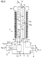
- FIG. 3 is a schematic circuit diagram of a HV divider according to an example embodiment of the present invention. At least some embodiments of the present invention addresses the above described issue in which a HV divider for measuring an input high voltage V IN in HV systems has an input terminal T IN to which it is applied the input high voltage V IN and which has an output terminal set T OUT , T OUT2 where a set of output voltages V OUT1 , V OUT2 are provided.
- the divider comprises a primary part P1 and a secondary part P2 electrically connected to each other so that the output of the primary part P1 is the input of the secondary part P2; wherein the input terminal of the primary part P1 is the divider input terminal T IN and the output the secondary part P2 is the divider output set T OUT1 , T OUT2 .
- the primary part P1 comprises a first assembly A1 and a second assembly A2 included within insulating means INS and having for input the same input terminal which is the divider input terminal T IN .
- the first assembly A1 is a first capacitor stack comprising a first high voltage capacitor C 1H and a middle voltage capacitor C M .
- the second assembly A2 comprises a second capacitor stack and a resistor stack electrically connected in parallel to each other.
- the second capacitor stack comprises a second high voltage capacitor C 2H and a low voltage capacitor C L .
- the resistor stack comprises a high voltage resistor R H and a low voltage resistor R L , both preferably being high accuracy/low inductance resistors.
- the output of the primary part P1 is a set of intermediary terminals T INT1 , T INT2 comprising at least:
- the insulating means INS around the two assemblies A1,A2 may be realized through three alternative solutions:
- the insulation body may be a cylindrically-shaped porcelain body (with or without sheds) or a fiberglass tube (with or without silicone sheds).
- the sheds are typically used fur insulating bodies located in AIS substations.
- the two assemblies A1, A2 - when inside the insulator body - are immersed in an insulating material which can be liquid (e.g. oil), gaseous (e.g. SF6) or solid (e.g. resin). It is noted that in latter case, i.e. when the two assemblies A1,A2 are immersed in a solid insulating material like resin, they may not require an insulator body around them since the solid insulating material can act as insulator body.
- liquid e.g. oil
- gaseous e.g. SF6
- solid e.g. resin
- the metallic envelope (also called enclosure) of the GIS usually contains other types of substation equipment as well.
- Each capacitor may be preferably made by alternating foils of aluminium, paper and/or polypropylene.
- One side of the primary part P1 is connected to high voltage, the other side is connected through a bushing to a base-box BB containing the electromagnetic unit U EM and to a terminal block, which may be inside or outside the base-box BB, where the second output terminal T OUT2 is provided.
- the secondary part P2 comprises an electromagnetic unit U EM and an output terminal set T OUT1 ,T OUT2 comprising at least:
- the electromagnetic unit U EM may comprise at least an inductive middle voltage transformer T IMV , a compensation reactor REACT and a filter circuit FILT.
- the HV divider may advantageously comprise:
- the first and third output terminal T OUT1 , T OUT3 are the terminals providing the functionalities typical of conventional CVTs, the first terminal subset T OUT1 is used for connection of carrier frequency equipment (e.g. for measuring and protecting purposes) and the third terminal T OUT3 is used for HF communication.
- the second output terminal T OUT2 is providing the functionality typical of RCDs, e.g. harmonics measurement. It may also be advantageously used by the customers for connection of low-voltage-power equipment.
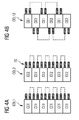
- Figure 4 is a schematic illustration of two different example embodiments of the physical realization of the two capacitor stacks.
- the first capacitor stack and the second capacitor stack are physically realized through two different column arrangements COL1, COL2.
- the first column arrangement COL1 comprises a set of first-stack capacitor elements CE1 physically stacked together one above the other and electrically connected.
- the second column arrangement COL2 includes a set of second-stack capacitor elements CE2 physically stacked together one above the other and electrically connected.
- the electrical connections as shown by the dashed line connecting the capacitor elements tags TG, may preferably be connections in series. In other embodiments, the electrical connections may be parallel connections or a combination of series and parallel.
- the first capacitor stack and the second capacitor stack are physically realized in one single column arrangement COL12.
- Such single column arrangement includes a number of capacitor elements CE1,CE2 belonging to both capacitor stacks.
- the capacitor elements of both capacitor stacks are physically stacked together one above the other together and only the capacitor elements CE1,CE2 belonging to the same capacitor stack are electrically connected, as shown by the dashed line connecting capacitor elements.
- the electrical connections, as shown by the dashed line connecting the capacitor elements tags TG, may preferably be connections in series. In other embodiments, the electrical connections may be parallel connections or a combination of series and parallel.
- the electrical connection of capacitor elements of the same capacitor stack is implemented via a given mixing rule.
- the mixing rule may be connecting the capacitor elements in an alternating sequence.
- mixing rules may be implemented using other types of mixing rules to electrically connect the capacitor elements CE1, CE2: e.g. mixing rules with alternating tuples (single, pairs, triples and so on or any combination thereof) of capacitor elements CE1, CE2 electrically connected together each to form one of the two corresponding capacitor stacks.
- the advantage of the first embodiment is that the simple design of electrical connections among capacitor elements is easy to implement so as to obtain manufacturing cost savings.
- the advantage of the second embodiment is that the dimensions and weight of the primary part P1 can be reduced.
- the reduced weight of the primary part P1 leads also to advantages in term of the civil works and installation costs required, especially in AIS substations.
- a less heavy HV divider requires a simpler and more economic metallic pedestal solution for ground fixing in order to fulfill the same mechanical robustness requirements.
- Mechanical robustness requirements in AIS substations are a sensitive issue for customers operating in regions with adverse climatic and geological conditions (e.g. strong winds, hurricanes, earthquakes etc.).
Landscapes
- Physics & Mathematics (AREA)
- General Physics & Mathematics (AREA)
- Engineering & Computer Science (AREA)
- Power Engineering (AREA)
- Measurement Of Current Or Voltage (AREA)
- Measuring Instrument Details And Bridges, And Automatic Balancing Devices (AREA)
- Transformers For Measuring Instruments (AREA)
- Dc-Dc Converters (AREA)
- Emergency Protection Circuit Devices (AREA)
- Circuit Arrangements For Discharge Lamps (AREA)
- Electrophonic Musical Instruments (AREA)
- Filters And Equalizers (AREA)
Priority Applications (9)
| Application Number | Priority Date | Filing Date | Title |
|---|---|---|---|
| EP13186318.5A EP2853903B1 (de) | 2013-09-27 | 2013-09-27 | Hochspannungsteiler |
| ES13186318.5T ES2607693T3 (es) | 2013-09-27 | 2013-09-27 | Divisor de alta tensión |
| BR112016006414A BR112016006414B8 (pt) | 2013-09-27 | 2014-08-19 | Divisor de alta-tensão |
| CN201480053354.0A CN105659097B (zh) | 2013-09-27 | 2014-08-19 | 高压分压器 |
| MX2016003780A MX353508B (es) | 2013-09-27 | 2014-08-19 | Un divisor de alto voltaje. |
| US15/025,352 US9714957B2 (en) | 2013-09-27 | 2014-08-19 | High voltage divider |
| CA2925370A CA2925370C (en) | 2013-09-27 | 2014-08-19 | A high voltage divider |
| PCT/EP2014/067634 WO2015043835A1 (en) | 2013-09-27 | 2014-08-19 | A high voltage divider |
| HRP20161513TT HRP20161513T1 (hr) | 2013-09-27 | 2016-11-15 | Visokonaponski razdjelnik |
Applications Claiming Priority (1)
| Application Number | Priority Date | Filing Date | Title |
|---|---|---|---|
| EP13186318.5A EP2853903B1 (de) | 2013-09-27 | 2013-09-27 | Hochspannungsteiler |
Publications (2)
| Publication Number | Publication Date |
|---|---|
| EP2853903A1 true EP2853903A1 (de) | 2015-04-01 |
| EP2853903B1 EP2853903B1 (de) | 2016-09-14 |
Family
ID=49231381
Family Applications (1)
| Application Number | Title | Priority Date | Filing Date |
|---|---|---|---|
| EP13186318.5A Active EP2853903B1 (de) | 2013-09-27 | 2013-09-27 | Hochspannungsteiler |
Country Status (9)
| Country | Link |
|---|---|
| US (1) | US9714957B2 (de) |
| EP (1) | EP2853903B1 (de) |
| CN (1) | CN105659097B (de) |
| BR (1) | BR112016006414B8 (de) |
| CA (1) | CA2925370C (de) |
| ES (1) | ES2607693T3 (de) |
| HR (1) | HRP20161513T1 (de) |
| MX (1) | MX353508B (de) |
| WO (1) | WO2015043835A1 (de) |
Cited By (9)
| Publication number | Priority date | Publication date | Assignee | Title |
|---|---|---|---|---|
| US20160274149A1 (en) * | 2012-11-16 | 2016-09-22 | Alstom Technology Ltd. | Very high-voltage dc line voltage sensor |
| WO2019154484A1 (en) * | 2018-02-07 | 2019-08-15 | Abb Schweiz Ag | High-frequency filter assembly |
| EP3543714A1 (de) * | 2018-03-23 | 2019-09-25 | General Electric Technology GmbH | Stromversorgungsvorrichtung und zugehöriges verfahren dafür |
| EP3671227A1 (de) * | 2018-12-18 | 2020-06-24 | 3M Innovative Properties Company | Isolator für freileitungsleiter |
| EP3780040A4 (de) * | 2018-05-31 | 2021-06-16 | Global Energy Interconnection Research Institute Co., Ltd | Breitbandiger spannungswandler |
| CN112997086A (zh) * | 2018-11-16 | 2021-06-18 | Abb瑞士股份有限公司 | 电压传感器和装置 |
| WO2022042826A1 (en) * | 2020-08-25 | 2022-03-03 | Hitachi Energy Switzerland Ag | A gas insulated surge arrester and a gas insulated surge arrester monitoring system |
| WO2022124942A1 (en) * | 2020-12-07 | 2022-06-16 | Gruppa Companiy Tel Obshchestvo S Ogranichennoy Otvetstvennostyu | Voltage sensor |
| CN115877057A (zh) * | 2021-09-27 | 2023-03-31 | 特变电工智慧能源有限公司 | 一种新型电磁式套管分压器 |
Families Citing this family (9)
| Publication number | Priority date | Publication date | Assignee | Title |
|---|---|---|---|---|
| US11038342B2 (en) | 2017-09-22 | 2021-06-15 | Schweitzer Engineering Laboratories, Inc. | Traveling wave identification using distortions for electric power system protection |
| US10802054B2 (en) | 2017-09-22 | 2020-10-13 | Schweitzer Engineering Laboratories, Inc. | High-fidelity voltage measurement using a capacitance-coupled voltage transformer |
| US10345363B2 (en) * | 2017-09-22 | 2019-07-09 | Schweitzer Engineering Laboratories, Inc. | High-fidelity voltage measurement using resistive divider in a capacitance-coupled voltage transformer |
| CN110850139B (zh) * | 2018-08-21 | 2022-02-01 | 西安西电高压开关有限责任公司 | 电压测量装置 |
| US11476705B2 (en) * | 2018-12-13 | 2022-10-18 | Abb Schweiz Ag | Capacitive power harvesting |
| US11187727B2 (en) | 2019-04-29 | 2021-11-30 | Schweitzer Engineering Laboratories, Inc. | Capacitance-coupled voltage transformer monitoring |
| CN111640554B (zh) * | 2020-06-10 | 2021-11-26 | 苏州电器科学研究院股份有限公司 | 一种电容式电压互感器 |
| CN112448483A (zh) * | 2020-10-16 | 2021-03-05 | 江苏思源赫兹互感器有限公司 | 一种高压交流限流器用cvt取能装置 |
| CN115420912A (zh) * | 2022-09-02 | 2022-12-02 | 大连北方互感器集团有限公司 | 一种带电磁电子式复合绝缘穿心式组合传感器 |
Citations (3)
| Publication number | Priority date | Publication date | Assignee | Title |
|---|---|---|---|---|
| EP1295133B1 (de) | 2000-05-03 | 2004-07-28 | Foroozan Ghassemi | Kapazitiver spannungswandler |
| US20100253366A1 (en) * | 2009-04-03 | 2010-10-07 | Deibele Craig E | Broadband high impedance pickoff circuit |
| WO2013026805A1 (en) * | 2011-08-19 | 2013-02-28 | Akademia Gorniczo-Hutnicza Im. Stanislawa Staszica W Krakowie | An adaptive voltage divider with corrected frequency characteristic for measuring high voltages |
Family Cites Families (4)
| Publication number | Priority date | Publication date | Assignee | Title |
|---|---|---|---|---|
| JP4089645B2 (ja) * | 2004-03-19 | 2008-05-28 | 株式会社村田製作所 | 高圧用可変抵抗器 |
| US7129693B2 (en) * | 2004-07-19 | 2006-10-31 | Fieldmetrics, Inc. | Modular voltage sensor |
| US7577235B2 (en) * | 2008-01-09 | 2009-08-18 | General Electric Company | Voltage generator of a radiation generator |
| CN202383182U (zh) * | 2011-12-30 | 2012-08-15 | 北京许继电力光学技术有限公司 | 一种光学电压互感器用高压电容分压器 |
-
2013
- 2013-09-27 ES ES13186318.5T patent/ES2607693T3/es active Active
- 2013-09-27 EP EP13186318.5A patent/EP2853903B1/de active Active
-
2014
- 2014-08-19 US US15/025,352 patent/US9714957B2/en active Active
- 2014-08-19 MX MX2016003780A patent/MX353508B/es active IP Right Grant
- 2014-08-19 WO PCT/EP2014/067634 patent/WO2015043835A1/en not_active Ceased
- 2014-08-19 CN CN201480053354.0A patent/CN105659097B/zh active Active
- 2014-08-19 CA CA2925370A patent/CA2925370C/en active Active
- 2014-08-19 BR BR112016006414A patent/BR112016006414B8/pt active IP Right Grant
-
2016
- 2016-11-15 HR HRP20161513TT patent/HRP20161513T1/hr unknown
Patent Citations (3)
| Publication number | Priority date | Publication date | Assignee | Title |
|---|---|---|---|---|
| EP1295133B1 (de) | 2000-05-03 | 2004-07-28 | Foroozan Ghassemi | Kapazitiver spannungswandler |
| US20100253366A1 (en) * | 2009-04-03 | 2010-10-07 | Deibele Craig E | Broadband high impedance pickoff circuit |
| WO2013026805A1 (en) * | 2011-08-19 | 2013-02-28 | Akademia Gorniczo-Hutnicza Im. Stanislawa Staszica W Krakowie | An adaptive voltage divider with corrected frequency characteristic for measuring high voltages |
Non-Patent Citations (5)
| Title |
|---|
| "HVDC Divider - Compensated voltage divider for HVDC transmission systems", 1 March 2012 (2012-03-01), pages 1 - 4, XP055103840, Retrieved from the Internet <URL:http://www.trenchgroup.com/content/download/1342/11179/file/DC Voltage Divider.pdf> [retrieved on 20140224] * |
| "Resistive Capacitive Voltage Transformers For Power Quality Applications Introduction", 1 March 2012 (2012-03-01), pages 1 - 4, XP055103839, Retrieved from the Internet <URL:http://www.trenchgroup.com/content/download/1382/11376/file/AC Voltage Divider.pdf> [retrieved on 20140224] * |
| COUTTS C ET AL: "Harmonic Voltage Measurements Using CVTs", IEEE TRANSACTIONS ON POWER DELIVERY, IEEE SERVICE CENTER, NEW YORK, NY, US, vol. 20, no. 1, 1 January 2005 (2005-01-01), pages 443 - 449, XP011124460, ISSN: 0885-8977, DOI: 10.1109/TPWRD.2004.837675 * |
| JOACHIM SCHMID ET AL: "Application of non conventional voltage and currents sensors in high voltage transmission and distribution systems", SMART MEASUREMENTS FOR FUTURE GRIDS (SMFG), 2011 IEEE INTERNATIONAL CONFERENCE ON, IEEE, 14 November 2011 (2011-11-14), pages 64 - 68, XP032090427, ISBN: 978-1-4577-1313-2, DOI: 10.1109/SMFG.2011.6125766 * |
| TRV COUPLING ET AL: "Capacitor Voltage Transformer TCVT TCC", 1 February 2012 (2012-02-01), pages 1 - 8, XP055103567, Retrieved from the Internet <URL:http://www.trenchgroup.com/content/download/1387/11386/file/TCVT and TCC_International Brochure.pdf> [retrieved on 20140221] * |
Cited By (18)
| Publication number | Priority date | Publication date | Assignee | Title |
|---|---|---|---|---|
| US20160274149A1 (en) * | 2012-11-16 | 2016-09-22 | Alstom Technology Ltd. | Very high-voltage dc line voltage sensor |
| US9766272B2 (en) * | 2012-11-16 | 2017-09-19 | Alstom Technology Ltd | Very high-voltage DC line voltage sensor |
| WO2019154484A1 (en) * | 2018-02-07 | 2019-08-15 | Abb Schweiz Ag | High-frequency filter assembly |
| EP3543714A1 (de) * | 2018-03-23 | 2019-09-25 | General Electric Technology GmbH | Stromversorgungsvorrichtung und zugehöriges verfahren dafür |
| EP3780040A4 (de) * | 2018-05-31 | 2021-06-16 | Global Energy Interconnection Research Institute Co., Ltd | Breitbandiger spannungswandler |
| CN112997086A (zh) * | 2018-11-16 | 2021-06-18 | Abb瑞士股份有限公司 | 电压传感器和装置 |
| EP3671227A1 (de) * | 2018-12-18 | 2020-06-24 | 3M Innovative Properties Company | Isolator für freileitungsleiter |
| WO2020128733A1 (en) * | 2018-12-18 | 2020-06-25 | 3M Innovative Properties Company | Insulator for overhead power line conductors |
| WO2022042826A1 (en) * | 2020-08-25 | 2022-03-03 | Hitachi Energy Switzerland Ag | A gas insulated surge arrester and a gas insulated surge arrester monitoring system |
| EP4205147A1 (de) * | 2020-08-25 | 2023-07-05 | Hitachi Energy Switzerland AG | Gasisolierter überspannungsableiter und gasisoliertes überspannungsableiterüberwachungssystem |
| JP2023539610A (ja) * | 2020-08-25 | 2023-09-15 | ヒタチ・エナジー・スウィツァーランド・アクチェンゲゼルシャフト | ガス絶縁サージアレスタおよびガス絶縁サージアレスタ監視システム |
| US12451275B2 (en) | 2020-08-25 | 2025-10-21 | Hitachi Energy Ltd | Gas insulated surge arrester and a gas insulated surge arrester monitoring system |
| EP4205147B1 (de) * | 2020-08-25 | 2026-02-25 | Hitachi Energy Ltd | Ein gasisolierter überspannungsableiter und ein überwachungssystem für gasisolierte überspannungsableiter |
| WO2022124942A1 (en) * | 2020-12-07 | 2022-06-16 | Gruppa Companiy Tel Obshchestvo S Ogranichennoy Otvetstvennostyu | Voltage sensor |
| CN116802505A (zh) * | 2020-12-07 | 2023-09-22 | 格鲁帕康派尼特尔有限责任公司 | 电压传感器 |
| US20240019466A1 (en) * | 2020-12-07 | 2024-01-18 | Gruppa Companiy Tel Obshchestvo S Ogranichennoy Otvetstvennostyu | Voltage sensor |
| US12517155B2 (en) * | 2020-12-07 | 2026-01-06 | Gruppa Companiy Tel Obshchestvo S Ogranichennoy Otvetstvennostyu | Voltage sensor |
| CN115877057A (zh) * | 2021-09-27 | 2023-03-31 | 特变电工智慧能源有限公司 | 一种新型电磁式套管分压器 |
Also Published As
| Publication number | Publication date |
|---|---|
| CN105659097A (zh) | 2016-06-08 |
| ES2607693T3 (es) | 2017-04-03 |
| CA2925370A1 (en) | 2015-04-02 |
| US9714957B2 (en) | 2017-07-25 |
| WO2015043835A1 (en) | 2015-04-02 |
| BR112016006414B8 (pt) | 2023-04-25 |
| BR112016006414A2 (pt) | 2017-08-01 |
| CA2925370C (en) | 2018-11-13 |
| CN105659097B (zh) | 2018-08-31 |
| BR112016006414B1 (pt) | 2022-07-12 |
| EP2853903B1 (de) | 2016-09-14 |
| HRP20161513T1 (hr) | 2016-12-16 |
| US20160238634A1 (en) | 2016-08-18 |
| MX353508B (es) | 2018-01-17 |
| MX2016003780A (es) | 2016-06-24 |
Similar Documents
| Publication | Publication Date | Title |
|---|---|---|
| EP2853903B1 (de) | Hochspannungsteiler | |
| US11287456B2 (en) | Capacitive compensated voltage sensor | |
| CN201812667U (zh) | 一种电子式电流电压组合互感器 | |
| CN101819868B (zh) | 一种特高压等电位屏蔽电容式电压互感器 | |
| CN102737828B (zh) | 带暂态过电压监测单元的电容式电压互感器 | |
| JP2018532249A (ja) | 過渡過電圧監視システム用のコンデンサ形計器用変圧器 | |
| US9008982B2 (en) | Systems and methods for determining residual flux in a power transformer | |
| CN103187162B (zh) | 用于电力系统的组合互感器 | |
| CN101424713A (zh) | 一种三相四线制高压电能计量方法及装置 | |
| CN201282017Y (zh) | 一种可现场进行误差调节的电容式电压互感器 | |
| EP2807664B1 (de) | Kombinationstransformator für ein stromsystem | |
| CN119619601A (zh) | 一种气体绝缘变电站用电容式电压互感器 | |
| CN217278639U (zh) | 一种电容测量电路及电子设备 | |
| EP1624312B1 (de) | Elektronischer messwandler zu kombinierten strom- und spannungsmessungen. | |
| CN100376897C (zh) | 一种能适应计量、测量或保护需要的高压信号取样方法 | |
| CN212275826U (zh) | 一种智能化电缆电压传感器 | |
| CN201378184Y (zh) | 一种三相四线制高压电能表 | |
| KR100787964B1 (ko) | 전자식 변성기(ect/evt)에 보조 전원공급 장치 및부분방전(pd)검출센서를 내장한 고전압 옥외용 에폭시수지 몰드형 전자식 mof | |
| CN203225140U (zh) | 紧凑型10kV电压监测绝缘子 | |
| CN209803216U (zh) | 一种带高压和低压隔离的电压互感器 | |
| CN109030909A (zh) | 一种配电一二次融合用三相电阻电抗分压式电压传感器 | |
| CN112180162A (zh) | 一种基于电容式电压互感器的谐波检测系统 | |
| CN207215882U (zh) | 节能型电容式电压互感器 | |
| CN202373447U (zh) | 用于电力系统的组合互感器 | |
| Sandler et al. | Measurement Systems for High Voltage Transients in Power Networks |
Legal Events
| Date | Code | Title | Description |
|---|---|---|---|
| PUAI | Public reference made under article 153(3) epc to a published international application that has entered the european phase |
Free format text: ORIGINAL CODE: 0009012 |
|
| 17P | Request for examination filed |
Effective date: 20130927 |
|
| AK | Designated contracting states |
Kind code of ref document: A1 Designated state(s): AL AT BE BG CH CY CZ DE DK EE ES FI FR GB GR HR HU IE IS IT LI LT LU LV MC MK MT NL NO PL PT RO RS SE SI SK SM TR |
|
| AX | Request for extension of the european patent |
Extension state: BA ME |
|
| R17P | Request for examination filed (corrected) |
Effective date: 20150420 |
|
| RBV | Designated contracting states (corrected) |
Designated state(s): AL AT BE BG CH CY CZ DE DK EE ES FI FR GB GR HR HU IE IS IT LI LT LU LV MC MK MT NL NO PL PT RO RS SE SI SK SM TR |
|
| 17Q | First examination report despatched |
Effective date: 20150626 |
|
| GRAP | Despatch of communication of intention to grant a patent |
Free format text: ORIGINAL CODE: EPIDOSNIGR1 |
|
| GRAJ | Information related to disapproval of communication of intention to grant by the applicant or resumption of examination proceedings by the epo deleted |
Free format text: ORIGINAL CODE: EPIDOSDIGR1 |
|
| GRAP | Despatch of communication of intention to grant a patent |
Free format text: ORIGINAL CODE: EPIDOSNIGR1 |
|
| RIC1 | Information provided on ipc code assigned before grant |
Ipc: G01R 15/06 20060101AFI20160309BHEP Ipc: H03H 7/24 20060101ALN20160309BHEP Ipc: G01R 15/16 20060101ALI20160309BHEP Ipc: G01R 15/14 20060101ALN20160309BHEP |
|
| INTG | Intention to grant announced |
Effective date: 20160322 |
|
| INTG | Intention to grant announced |
Effective date: 20160411 |
|
| GRAS | Grant fee paid |
Free format text: ORIGINAL CODE: EPIDOSNIGR3 |
|
| GRAA | (expected) grant |
Free format text: ORIGINAL CODE: 0009210 |
|
| AK | Designated contracting states |
Kind code of ref document: B1 Designated state(s): AL AT BE BG CH CY CZ DE DK EE ES FI FR GB GR HR HU IE IS IT LI LT LU LV MC MK MT NL NO PL PT RO RS SE SI SK SM TR |
|
| REG | Reference to a national code |
Ref country code: GB Ref legal event code: FG4D Ref country code: FR Ref legal event code: PLFP Year of fee payment: 4 |
|
| REG | Reference to a national code |
Ref country code: CH Ref legal event code: EP Ref country code: CH Ref legal event code: NV Representative=s name: SIEMENS SCHWEIZ AG, CH |
|
| REG | Reference to a national code |
Ref country code: IE Ref legal event code: FG4D |
|
| REG | Reference to a national code |
Ref country code: AT Ref legal event code: REF Ref document number: 829568 Country of ref document: AT Kind code of ref document: T Effective date: 20161015 |
|
| REG | Reference to a national code |
Ref country code: DE Ref legal event code: R096 Ref document number: 602013011395 Country of ref document: DE |
|
| REG | Reference to a national code |
Ref country code: HR Ref legal event code: TUEP Ref document number: P20161513 Country of ref document: HR |
|
| REG | Reference to a national code |
Ref country code: HR Ref legal event code: T1PR Ref document number: P20161513 Country of ref document: HR |
|
| REG | Reference to a national code |
Ref country code: SE Ref legal event code: TRGR |
|
| REG | Reference to a national code |
Ref country code: LT Ref legal event code: MG4D |
|
| REG | Reference to a national code |
Ref country code: NL Ref legal event code: MP Effective date: 20160914 |
|
| PG25 | Lapsed in a contracting state [announced via postgrant information from national office to epo] |
Ref country code: RS Free format text: LAPSE BECAUSE OF FAILURE TO SUBMIT A TRANSLATION OF THE DESCRIPTION OR TO PAY THE FEE WITHIN THE PRESCRIBED TIME-LIMIT Effective date: 20160914 Ref country code: NO Free format text: LAPSE BECAUSE OF FAILURE TO SUBMIT A TRANSLATION OF THE DESCRIPTION OR TO PAY THE FEE WITHIN THE PRESCRIBED TIME-LIMIT Effective date: 20161214 Ref country code: LT Free format text: LAPSE BECAUSE OF FAILURE TO SUBMIT A TRANSLATION OF THE DESCRIPTION OR TO PAY THE FEE WITHIN THE PRESCRIBED TIME-LIMIT Effective date: 20160914 Ref country code: FI Free format text: LAPSE BECAUSE OF FAILURE TO SUBMIT A TRANSLATION OF THE DESCRIPTION OR TO PAY THE FEE WITHIN THE PRESCRIBED TIME-LIMIT Effective date: 20160914 |
|
| PG25 | Lapsed in a contracting state [announced via postgrant information from national office to epo] |
Ref country code: BE Free format text: LAPSE BECAUSE OF NON-PAYMENT OF DUE FEES Effective date: 20160930 Ref country code: NL Free format text: LAPSE BECAUSE OF FAILURE TO SUBMIT A TRANSLATION OF THE DESCRIPTION OR TO PAY THE FEE WITHIN THE PRESCRIBED TIME-LIMIT Effective date: 20160914 Ref country code: LV Free format text: LAPSE BECAUSE OF FAILURE TO SUBMIT A TRANSLATION OF THE DESCRIPTION OR TO PAY THE FEE WITHIN THE PRESCRIBED TIME-LIMIT Effective date: 20160914 Ref country code: GR Free format text: LAPSE BECAUSE OF FAILURE TO SUBMIT A TRANSLATION OF THE DESCRIPTION OR TO PAY THE FEE WITHIN THE PRESCRIBED TIME-LIMIT Effective date: 20161215 |
|
| PG25 | Lapsed in a contracting state [announced via postgrant information from national office to epo] |
Ref country code: EE Free format text: LAPSE BECAUSE OF FAILURE TO SUBMIT A TRANSLATION OF THE DESCRIPTION OR TO PAY THE FEE WITHIN THE PRESCRIBED TIME-LIMIT Effective date: 20160914 Ref country code: RO Free format text: LAPSE BECAUSE OF FAILURE TO SUBMIT A TRANSLATION OF THE DESCRIPTION OR TO PAY THE FEE WITHIN THE PRESCRIBED TIME-LIMIT Effective date: 20160914 |
|
| PG25 | Lapsed in a contracting state [announced via postgrant information from national office to epo] |
Ref country code: IS Free format text: LAPSE BECAUSE OF FAILURE TO SUBMIT A TRANSLATION OF THE DESCRIPTION OR TO PAY THE FEE WITHIN THE PRESCRIBED TIME-LIMIT Effective date: 20170114 Ref country code: PT Free format text: LAPSE BECAUSE OF FAILURE TO SUBMIT A TRANSLATION OF THE DESCRIPTION OR TO PAY THE FEE WITHIN THE PRESCRIBED TIME-LIMIT Effective date: 20170116 Ref country code: BG Free format text: LAPSE BECAUSE OF FAILURE TO SUBMIT A TRANSLATION OF THE DESCRIPTION OR TO PAY THE FEE WITHIN THE PRESCRIBED TIME-LIMIT Effective date: 20161214 Ref country code: SK Free format text: LAPSE BECAUSE OF FAILURE TO SUBMIT A TRANSLATION OF THE DESCRIPTION OR TO PAY THE FEE WITHIN THE PRESCRIBED TIME-LIMIT Effective date: 20160914 Ref country code: PL Free format text: LAPSE BECAUSE OF FAILURE TO SUBMIT A TRANSLATION OF THE DESCRIPTION OR TO PAY THE FEE WITHIN THE PRESCRIBED TIME-LIMIT Effective date: 20160914 Ref country code: BE Free format text: LAPSE BECAUSE OF FAILURE TO SUBMIT A TRANSLATION OF THE DESCRIPTION OR TO PAY THE FEE WITHIN THE PRESCRIBED TIME-LIMIT Effective date: 20160914 Ref country code: SM Free format text: LAPSE BECAUSE OF FAILURE TO SUBMIT A TRANSLATION OF THE DESCRIPTION OR TO PAY THE FEE WITHIN THE PRESCRIBED TIME-LIMIT Effective date: 20160914 Ref country code: CZ Free format text: LAPSE BECAUSE OF FAILURE TO SUBMIT A TRANSLATION OF THE DESCRIPTION OR TO PAY THE FEE WITHIN THE PRESCRIBED TIME-LIMIT Effective date: 20160914 |
|
| REG | Reference to a national code |
Ref country code: DE Ref legal event code: R097 Ref document number: 602013011395 Country of ref document: DE |
|
| REG | Reference to a national code |
Ref country code: IE Ref legal event code: MM4A |
|
| REG | Reference to a national code |
Ref country code: AT Ref legal event code: UEP Ref document number: 829568 Country of ref document: AT Kind code of ref document: T Effective date: 20160914 |
|
| PLBE | No opposition filed within time limit |
Free format text: ORIGINAL CODE: 0009261 |
|
| STAA | Information on the status of an ep patent application or granted ep patent |
Free format text: STATUS: NO OPPOSITION FILED WITHIN TIME LIMIT |
|
| PG25 | Lapsed in a contracting state [announced via postgrant information from national office to epo] |
Ref country code: IE Free format text: LAPSE BECAUSE OF NON-PAYMENT OF DUE FEES Effective date: 20160927 Ref country code: DK Free format text: LAPSE BECAUSE OF FAILURE TO SUBMIT A TRANSLATION OF THE DESCRIPTION OR TO PAY THE FEE WITHIN THE PRESCRIBED TIME-LIMIT Effective date: 20160914 |
|
| 26N | No opposition filed |
Effective date: 20170615 |
|
| PG25 | Lapsed in a contracting state [announced via postgrant information from national office to epo] |
Ref country code: LU Free format text: LAPSE BECAUSE OF NON-PAYMENT OF DUE FEES Effective date: 20160927 |
|
| REG | Reference to a national code |
Ref country code: FR Ref legal event code: PLFP Year of fee payment: 5 |
|
| REG | Reference to a national code |
Ref country code: CH Ref legal event code: PCOW Free format text: NEW ADDRESS: WERNER-VON-SIEMENS-STRASSE 1, 80333 MUENCHEN (DE) |
|
| PG25 | Lapsed in a contracting state [announced via postgrant information from national office to epo] |
Ref country code: SI Free format text: LAPSE BECAUSE OF FAILURE TO SUBMIT A TRANSLATION OF THE DESCRIPTION OR TO PAY THE FEE WITHIN THE PRESCRIBED TIME-LIMIT Effective date: 20160914 |
|
| REG | Reference to a national code |
Ref country code: HR Ref legal event code: PNAN Ref document number: P20161513 Country of ref document: HR Owner name: SIEMENS AKTIENGESELLSCHAFT, DE |
|
| GBPC | Gb: european patent ceased through non-payment of renewal fee |
Effective date: 20170927 |
|
| PG25 | Lapsed in a contracting state [announced via postgrant information from national office to epo] |
Ref country code: HU Free format text: LAPSE BECAUSE OF FAILURE TO SUBMIT A TRANSLATION OF THE DESCRIPTION OR TO PAY THE FEE WITHIN THE PRESCRIBED TIME-LIMIT; INVALID AB INITIO Effective date: 20130927 |
|
| PG25 | Lapsed in a contracting state [announced via postgrant information from national office to epo] |
Ref country code: MT Free format text: LAPSE BECAUSE OF NON-PAYMENT OF DUE FEES Effective date: 20160930 Ref country code: MK Free format text: LAPSE BECAUSE OF FAILURE TO SUBMIT A TRANSLATION OF THE DESCRIPTION OR TO PAY THE FEE WITHIN THE PRESCRIBED TIME-LIMIT Effective date: 20160914 Ref country code: CY Free format text: LAPSE BECAUSE OF FAILURE TO SUBMIT A TRANSLATION OF THE DESCRIPTION OR TO PAY THE FEE WITHIN THE PRESCRIBED TIME-LIMIT Effective date: 20160914 Ref country code: MC Free format text: LAPSE BECAUSE OF FAILURE TO SUBMIT A TRANSLATION OF THE DESCRIPTION OR TO PAY THE FEE WITHIN THE PRESCRIBED TIME-LIMIT Effective date: 20160914 |
|
| PG25 | Lapsed in a contracting state [announced via postgrant information from national office to epo] |
Ref country code: GB Free format text: LAPSE BECAUSE OF NON-PAYMENT OF DUE FEES Effective date: 20170927 |
|
| REG | Reference to a national code |
Ref country code: FR Ref legal event code: PLFP Year of fee payment: 6 |
|
| PG25 | Lapsed in a contracting state [announced via postgrant information from national office to epo] |
Ref country code: AL Free format text: LAPSE BECAUSE OF FAILURE TO SUBMIT A TRANSLATION OF THE DESCRIPTION OR TO PAY THE FEE WITHIN THE PRESCRIBED TIME-LIMIT Effective date: 20160914 |
|
| REG | Reference to a national code |
Ref country code: HR Ref legal event code: ODRP Ref document number: P20161513 Country of ref document: HR Payment date: 20190906 Year of fee payment: 7 |
|
| REG | Reference to a national code |
Ref country code: HR Ref legal event code: ODRP Ref document number: P20161513 Country of ref document: HR Payment date: 20200917 Year of fee payment: 8 |
|
| REG | Reference to a national code |
Ref country code: DE Ref legal event code: R081 Ref document number: 602013011395 Country of ref document: DE Owner name: HSP HOCHSPANNUNGSGERAETE GMBH, DE Free format text: FORMER OWNER: SIEMENS AKTIENGESELLSCHAFT, 80333 MUENCHEN, DE Ref country code: DE Ref legal event code: R081 Ref document number: 602013011395 Country of ref document: DE Owner name: SIEMENS ENERGY GLOBAL GMBH & CO. KG, DE Free format text: FORMER OWNER: SIEMENS AKTIENGESELLSCHAFT, 80333 MUENCHEN, DE |
|
| REG | Reference to a national code |
Ref country code: HR Ref legal event code: ODRP Ref document number: P20161513 Country of ref document: HR Payment date: 20210920 Year of fee payment: 9 |
|
| REG | Reference to a national code |
Ref country code: HR Ref legal event code: ODRP Ref document number: P20161513 Country of ref document: HR Payment date: 20220919 Year of fee payment: 10 |
|
| REG | Reference to a national code |
Ref country code: AT Ref legal event code: PC Ref document number: 829568 Country of ref document: AT Kind code of ref document: T Owner name: SIEMENS ENERGY GLOBAL GMBH & CO. KG, DE Effective date: 20221018 |
|
| REG | Reference to a national code |
Ref country code: HR Ref legal event code: PPPP Ref document number: P20161513 Country of ref document: HR Owner name: SIEMENS ENERGY GLOBAL GMBH & CO. KG, DE |
|
| REG | Reference to a national code |
Ref country code: HR Ref legal event code: ODRP Ref document number: P20161513 Country of ref document: HR Payment date: 20230912 Year of fee payment: 11 |
|
| REG | Reference to a national code |
Ref country code: ES Ref legal event code: PC2A Owner name: SIEMENS ENERGY GLOBAL GMBH & CO. KG Effective date: 20240403 |
|
| REG | Reference to a national code |
Ref country code: HR Ref legal event code: PPPP Ref document number: P20161513 Country of ref document: HR Owner name: HSP HOCHSPANNUNGSGERAETE GMBH, DE |
|
| REG | Reference to a national code |
Ref country code: DE Ref legal event code: R081 Ref document number: 602013011395 Country of ref document: DE Owner name: HSP HOCHSPANNUNGSGERAETE GMBH, DE Free format text: FORMER OWNER: SIEMENS ENERGY GLOBAL GMBH & CO. KG, 81739 MUENCHEN, DE |
|
| REG | Reference to a national code |
Ref country code: HR Ref legal event code: ODRP Ref document number: P20161513 Country of ref document: HR Payment date: 20240917 Year of fee payment: 12 |
|
| REG | Reference to a national code |
Ref country code: AT Ref legal event code: PC Ref document number: 829568 Country of ref document: AT Kind code of ref document: T Owner name: HSP HOCHSPANNUNGSGERAETE GMBH, DE Effective date: 20241016 |
|
| REG | Reference to a national code |
Ref country code: ES Ref legal event code: PC2A Owner name: HSP HOCHSPANNUNGSGERAETE GMBH Effective date: 20250206 |
|
| REG | Reference to a national code |
Ref country code: CH Ref legal event code: U11 Free format text: ST27 STATUS EVENT CODE: U-0-0-U10-U11 (AS PROVIDED BY THE NATIONAL OFFICE) Effective date: 20251001 |
|
| PGFP | Annual fee paid to national office [announced via postgrant information from national office to epo] |
Ref country code: DE Payment date: 20250929 Year of fee payment: 13 |
|
| REG | Reference to a national code |
Ref country code: HR Ref legal event code: ODRP Ref document number: P20161513 Country of ref document: HR Payment date: 20250911 Year of fee payment: 13 |
|
| PGFP | Annual fee paid to national office [announced via postgrant information from national office to epo] |
Ref country code: TR Payment date: 20250908 Year of fee payment: 13 Ref country code: IT Payment date: 20250919 Year of fee payment: 13 |
|
| PGFP | Annual fee paid to national office [announced via postgrant information from national office to epo] |
Ref country code: HR Payment date: 20250911 Year of fee payment: 13 |
|
| PGFP | Annual fee paid to national office [announced via postgrant information from national office to epo] |
Ref country code: FR Payment date: 20250925 Year of fee payment: 13 Ref country code: AT Payment date: 20250929 Year of fee payment: 13 |
|
| PGFP | Annual fee paid to national office [announced via postgrant information from national office to epo] |
Ref country code: SE Payment date: 20250927 Year of fee payment: 13 |
|
| PGFP | Annual fee paid to national office [announced via postgrant information from national office to epo] |
Ref country code: CH Payment date: 20251001 Year of fee payment: 13 |
|
| PGFP | Annual fee paid to national office [announced via postgrant information from national office to epo] |
Ref country code: ES Payment date: 20251001 Year of fee payment: 13 |