EP2853928A2 - Système et procédé de support de câble marin - Google Patents
Système et procédé de support de câble marin Download PDFInfo
- Publication number
- EP2853928A2 EP2853928A2 EP14150969.5A EP14150969A EP2853928A2 EP 2853928 A2 EP2853928 A2 EP 2853928A2 EP 14150969 A EP14150969 A EP 14150969A EP 2853928 A2 EP2853928 A2 EP 2853928A2
- Authority
- EP
- European Patent Office
- Prior art keywords
- cable section
- marine cable
- section
- torque
- bench
- Prior art date
- Legal status (The legal status is an assumption and is not a legal conclusion. Google has not performed a legal analysis and makes no representation as to the accuracy of the status listed.)
- Withdrawn
Links
Images


Classifications
-
- G—PHYSICS
- G01—MEASURING; TESTING
- G01V—GEOPHYSICS; GRAVITATIONAL MEASUREMENTS; DETECTING MASSES OR OBJECTS; TAGS
- G01V13/00—Manufacturing, calibrating, cleaning, or repairing instruments or devices covered by groups G01V1/00 – G01V11/00
-
- B—PERFORMING OPERATIONS; TRANSPORTING
- B23—MACHINE TOOLS; METAL-WORKING NOT OTHERWISE PROVIDED FOR
- B23P—METAL-WORKING NOT OTHERWISE PROVIDED FOR; COMBINED OPERATIONS; UNIVERSAL MACHINE TOOLS
- B23P6/00—Restoring or reconditioning objects
-
- G—PHYSICS
- G01—MEASURING; TESTING
- G01V—GEOPHYSICS; GRAVITATIONAL MEASUREMENTS; DETECTING MASSES OR OBJECTS; TAGS
- G01V1/00—Seismology; Seismic or acoustic prospecting or detecting
- G01V1/38—Seismology; Seismic or acoustic prospecting or detecting specially adapted for water-covered areas
-
- G—PHYSICS
- G01—MEASURING; TESTING
- G01V—GEOPHYSICS; GRAVITATIONAL MEASUREMENTS; DETECTING MASSES OR OBJECTS; TAGS
- G01V1/00—Seismology; Seismic or acoustic prospecting or detecting
- G01V1/16—Receiving elements for seismic signals; Arrangements or adaptations of receiving elements
- G01V1/20—Arrangements of receiving elements, e.g. geophone pattern
- G01V1/201—Constructional details of seismic cables, e.g. streamers
- G01V2001/204—Reinforcements, e.g. by tensioning cables
-
- G—PHYSICS
- G01—MEASURING; TESTING
- G01V—GEOPHYSICS; GRAVITATIONAL MEASUREMENTS; DETECTING MASSES OR OBJECTS; TAGS
- G01V2210/00—Details of seismic processing or analysis
- G01V2210/10—Aspects of acoustic signal generation or detection
- G01V2210/14—Signal detection
- G01V2210/142—Receiver location
- G01V2210/1423—Sea
-
- Y—GENERAL TAGGING OF NEW TECHNOLOGICAL DEVELOPMENTS; GENERAL TAGGING OF CROSS-SECTIONAL TECHNOLOGIES SPANNING OVER SEVERAL SECTIONS OF THE IPC; TECHNICAL SUBJECTS COVERED BY FORMER USPC CROSS-REFERENCE ART COLLECTIONS [XRACs] AND DIGESTS
- Y10—TECHNICAL SUBJECTS COVERED BY FORMER USPC
- Y10T—TECHNICAL SUBJECTS COVERED BY FORMER US CLASSIFICATION
- Y10T29/00—Metal working
- Y10T29/49—Method of mechanical manufacture
- Y10T29/49764—Method of mechanical manufacture with testing or indicating
-
- Y—GENERAL TAGGING OF NEW TECHNOLOGICAL DEVELOPMENTS; GENERAL TAGGING OF CROSS-SECTIONAL TECHNOLOGIES SPANNING OVER SEVERAL SECTIONS OF THE IPC; TECHNICAL SUBJECTS COVERED BY FORMER USPC CROSS-REFERENCE ART COLLECTIONS [XRACs] AND DIGESTS
- Y10—TECHNICAL SUBJECTS COVERED BY FORMER USPC
- Y10T—TECHNICAL SUBJECTS COVERED BY FORMER US CLASSIFICATION
- Y10T29/00—Metal working
- Y10T29/51—Plural diverse manufacturing apparatus including means for metal shaping or assembling
- Y10T29/5187—Wire working
Definitions
- Embodiments of the subject matter disclosed herein generally relate to methods and systems and, more particularly, to mechanisms and techniques for releasing a torque in a seismic cable section prior to inserting various sensors inside the seismic cable.
- Marine seismic data acquisition and processing generate a profile (image) of the geophysical structure (subsurface) under the seafloor. While this profile does not provide an accurate location for oil and gas reservoirs, it suggests, to those trained in the field, the presence or absence of reservoirs. Thus, providing a high-resolution image of the subsurface is an ongoing process for the exploration of natural resources, including, among others, oil and/or gas.
- a seismic survey system 100 includes a vessel 102 that tows plural seismic sensors 104 distributed along a seismic cable 106.
- Vessel 102 may tow plural seismic cables 106 at the same time.
- the seismic cables may be disposed horizontally, i.e., lying at a constant depth z 1 relative to the ocean's surface 110.
- the plural seismic cables 106 may form a constant angle (i.e., the seismic cables may be slanted) with respect to the surface of the ocean as disclosed in U.S. Patent No. 4,992,992 , the entire content of which is incorporated herein by reference.
- each seismic cable may have a head float 106a and a tail float 106b connected to its respective ends for maintaining given depth z 1 .
- a front-end gear 112 that includes various cables connects seismic cables 106 to vessel 102.
- Vessel 102 also tows a sound source 120 configured to generate an acoustic wave 122a, which propagates downward and penetrates the seafloor 124, eventually being reflected by a reflecting structure 126 (reflector).
- the reflected acoustic wave 122b propagates upward and is detected by seismic sensors 104.
- Figure 1 shows only one path 122a corresponding to the acoustic wave.
- the recorded traces may be used to determine an image of the subsurface (i.e., earth structure below surface 124).
- the seismic sensors used in the seismic cable need to perform as designed, i.e., to have actual characteristics that conform with the design characteristics envisioned by the design engineer.
- the seismic sensors are supposed to be aligned with one or more given directions within the seismic cable, and during the processing phase, this alignment is assumed to be obeyed by all seismic cables. If the alignment is not present, the recorded seismic data might be wrongly processed, generating inaccurate images of the surveyed surface.
- each sensor needs to be aligned relative to a given direction of the seismic cable so that individual sensors in the array receive signals from the same direction.
- This alignment normally takes place during the manufacturing phase, when the seismic cable has inherent torque.
- inherent torque may be a consequence of manipulating, manufacturing, rolling, etc., of the cable during manufacturing or transport (e.g., from the manufacturing facility to the vessel designated to tow the seismic cable).
- the seismic cable is towed through the water during normal data acquisition, there are no forces acting on it to counteract its inherent torque and, therefore, the seismic cable is free to rotate about its axis.
- this cable rotation happens during data acquisition, it negatively impacts the recorded data because sections of the cable will have different orientations, resulting in sensors belonging to a same array having different orientations.
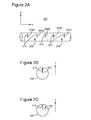
- Figure 2A shows a seismic cable 200 considered to have, among many sections, sections 202 and 204. Sections 202 and 204 do not have to be physically different portions of the seismic cable. Sensors 202a in section 202 and sensors 204a in section 204 are aligned during the manufacturing process so that they all have their axes 210 and 220 parallel with, e.g., gravity, which is represented by axis Z in the figure.
- a cross-section view of seismic cable 200 is shown in Figure 2B , illustrating that all the sensors' orientations coincide, i.e., arrows 210 and 220 are aligned with axis Z.
- section 204 may rotate relative to section 202 so that arrows 210 and 220 of corresponding sensors 202a and 204a are offset as illustrated in Figure 2C , which is a cross-sectional view of seismic cable 200 during operation.
- sensors 202a and 202b are connected together to form an array, their different orientations in the same array introduce inaccuracies in the recorded data, which is undesirable.
- MEMS devices can be used to form an array digitally, but digital signals from the MEMS devices must be individually processed. This requires additional data channels and, therefore, much higher data bandwidth and increased power consumption.
- a torque relief system for dissipating a torque in a marine cable section to be used for seismic data collection.
- the system includes a bench having a deadman unit; a tensioning element connected to the deadman unit; a swivel bearing unit connected to the tensioning element and configured to receive a first end of the marine cable section; and at least one bearing unit configured to support the marine cable section with reduced friction so that when the tensioning element tenses the marine cable section, the marine cable section and the first end rotate freely until the torque is dissipated.
- the torque relief system may further comprise plural clamping units distributed along the bench and configured to fix the marine cable section in place when the torque has dissipated.
- the bearing unit is an air bearing unit that releases air toward the marine cable section.
- the marine cable section may comprise hydrophones and/or particle motion sensors.
- the torque relief system for example further comprises at least a support element associated with the at least one bearing unit for supporting a weight of the marine cable section when not tensed.
- the swivel bearing unit may be configured to have small rotational friction and high resistance to tension.
- the torque relief system may further comprise another swivel bearing unit connected between a second end of the marine cable section and another deadman unit of the bench.
- the torque relief system further comprises a seismic cable angle measurement apparatus for determining an angular alignment of sensors mounted in the marine cable section, the apparatus including one or more digital protractors and an angle recording camera.
- the torque relief system further comprises, for example, a position device configured to determine an offset of an angular position of a magnet attached to a sensor inside the marine cable section relative to a reference.
- the offset may be stored and used during data processing.
- bearing units, support elements and clamping units are attached to the bench to support the marine cable section and they may be configured to be adjustable relative to the bench for obtaining a straight line marine cable section.
- a length of the bench may for example be longer than 100 m.
- a method for dissipating a torque in a marine cable section to be used for seismic data collection includes placing the marine cable section along a bench; supporting the marine cable section with bearing units to reduce a torsional friction between the marine cable section and the bench; tensing the marine cable section to dissipate a torque formed inside the marine cable section while the torsional friction is reduced; and inserting sensors inside the marine cable section.
- the method may further comprise:
- the swivel bearing unit may be selected to have small rotational friction and high resistance to tension.
- the method further comprises, in a particular embodiment:
- the method may further comprise:
- the method further comprises:
- the method may further comprise:
- a manufacturing technique is required to align the particle motion sensors during the manufacturing process.
- This method is also applicable to other type of sensors present inside the seismic cable, for example, a hydrophone, geophone, etc.
- the seismic includes both hydrophones and particle motion sensors.
- This manufacturing technique provides a method to measure and record the sensors' rotation angles once assembled into the seismic cable. Once the seismic cable is tensed without friction, it is free to rotate along its length and relieve internal torque as it would when towed behind a seismic vessel.
- a torque relief system 300 may extend over a long distance D, for example, 150 m.
- a seismic cable may have a length of about 10 km and may include multiple sections 302, each having a length substantially equal to D. These sections connect to each other to form the seismic cable.
- System 300 provides support for the entire length of a section 302.
- one or more benches 304 extend across the floor 306 inside the production facility to support the entire seismic cable section 302.
- a deadman part 310 is fixedly attached either to the floor 306 or to bench 304. This deadman part needs to be strong and it needs to resist the effect of forces that appear when section 302 is tensed as discussed later.
- a tensioning element 320 is attached with one end to deadman part 310 and with another end to a swivel bearing unit 330. Tensioning element 320 may be activated to tense the seismic cable as discussed later. It may be an electric or pneumatic device or any other appropriate device known in the art. In one application, tensioning element 320 has a central member 322 that can extend away or toward the tensioning element's body so that tension is applied or removed from section 320.
- Swivel bearing unit 330 is connected between an end 302a of section 302 and tensioning element 320 such that end 302a of section 302 can freely rotate when section 302 is under tension.
- swivel bearing unit 330 offers minimal rotational friction to end 302a of section 302 so that section 302 is almost free to rotate about longitudinal axis X.
- the other end 302b of section 302 may be connected to another deadman 314 or to another swivel bearing unit (not shown).
- Swivel bearing unit 330 may have wheels 332 for moving along the bench when the tensioning element 320 tenses section 302. Any known swivel bearing unit may be used as long as this unit promotes free rotation of section 302 and is designed to withstand the tension applied to this section.
- frictionless bearing units 340i are located at various positions along section 302, on bench 304, for providing frictionless support for the entire section 302. Thus, in this way, not only one or both ends of section 302 but the entire section is permitted to freely rotate to relieve torsional stress.
- frictionless bearing unit 340i is an air bearing, i.e., an active bearing unit in which air or another fluid is pumped from a pump 342 and provided between the air bearing and section 302 for preventing direct contact between section 302 and an upper surface 344i of the air bearing.
- friction between section 302 and frictionless bearing unit 340i is reduced to promote dissipation of torsional stress.
- a support element 350i may be located next to a corresponding bearing unit 340i so that when seismic cable 302 is not tensed, part of its weight is supported by support elements 350i and not by frictionless bearing units 340i.
- support elements 350i are optional.
- a simple support element may include a pole that has one end attached to the bench and the other configured to support a roller that contacts section 302. More sophisticated support elements may be used as will be appreciated by those skilled in the art.
- One or more clamping units 370i may also be mounted on bench 304 for clamping section 302 in place when inherent torque has been relieved.
- Clamping units 370i are distributed along section 302 and in one application, they are located close (e.g., at predetermined distances) to positions 380i where sensors 382i need to be inserted into section 302.
- Clamping units 370i may be activated mechanically, electrically or pneumatically for clamping section 302. In one application they are automatically activated. In another application, they are manually activated. Having clamping units next to positions where the sensors need to be inserted expedites the seismic cable manufacturing process because either the operator or robots may automatically insert the sensors while relying on the clamping sections as reference points.
- the clamping sections may be arranged in such a way that the operator or robot is instructed to insert a sensor at a given distance I from each clamping unit.
- bench 304 may be provided with adjustable legs 308 for leveling the bench as desired.
- the entire bench 304 is adjusted to have a small angle (for example, a few degrees) with floor 306.
- Elements 340i, 350i and 370i may be attached to bench 304 in such a manner that their positions may be adjusted, either automatically or manually in an XY plane, where the XY plane coincides with the top of bench 304. In this way, elements 340i, 350i and 370i may be adjusted so that section 302 extends along a straight line, which promotes dissipation of inherent torque.
- a seismic cable angle measurement apparatus 390 may be used to determine an angular alignment of the sensors.
- Seismic cable angle measurement apparatus 390 (also called position device) may include one or more digital protractors 392 attached to the marine cable, i.e., section 302 and an angle recording apparatus 394, which may be a computer running recording software or a magnetic camera.
- element 392 is a magnet (e.g., a permanent magnet) which has a known position relative to a sensor or another element inside the streamer cable and element 394 is a magnetic camera or a proximity sensor.
- a proximity sensor has as output a voltage which increases as a distance between the proximity sensor and the magnet decreases. The proximity sensor has an advantage that it removes the human interface in the process by simply detecting the highest voltage output, i.e., the entire alignment process may be automatized.
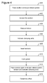
- step 400 a section 302 is placed on the torque relief system 300. At least one end of the section is attached to a swivel bearing unit 330, and the other end of the section is attached either to deadman 314 or another swivel bearing unit. Then, after section 302 is verified to lie over bearing units 340i and support elements 350i and also to extend by clamping units 370i, a tensioning element 320, located between deadman 314 and swivel bearing unit 330, is actuated in step 402 to tense section 302.
- bearing units 340i are activated to minimize friction between section 302 and system 300.
- section 302 does not have at this time either the jacket 502 or sensors 382.
- Torsional torque that has accumulated in section 302 during the manufacturing process is now free to dissipate because section 302 can almost freely rotate about its longitudinal axis.
- torsional torque has been relieved and the clamping units are activated in step 406 to fix the angular position of section 302.
- one or more sensors 382 are inserted inside section 302 at predetermined positions, e.g., relative to each clamping unit.
- This step may include mechanically attaching the sensor to a section's component and electrically connecting the sensor to one or more electrical cables present inside section 302. Further, this step may include aligning the particle motion sensors by attaching keyed supports to the clamped section, which then interlock with keys built into the particle motion sensor's mounting structure.
- section 302 is released from the clamping units and taken in step 410 for another manufacturing process during which the jacket is formed over the section's exterior. During this step, section 302 may be removed from system 300. After this, section 302 is brought back to system 300 and again tensed in step 412 to relieve any additional torsional torque, after which the section is clamped in place.
- Seismic cable angle measurement apparatus 390 is used in step 414 for determining the sensors' offset. More specifically, the sensors may be equipped with a small magnet permanently embedded in the sensor carrier and aligned with the sensor's sensitive axis. Magnetic camera 394 associated with digital protractor 392 may be used to locate the sensors' rotational alignment relative to a reference, e.g., tilt meter. Alternatively, proximity sensor 394 is used to determine the angular position of the magnet, and implicitly, the sensor associated with the magnet. The rotational angle of a sensor or sensor array compared to the tilt meter reading may be recorded into the tilt meter or other component of a seismic acquisition system as offset. This offset is then used to accurately report the sensor array's angular orientation when towed through the water or the offset of each sensor. In one application, the offset of each sensor is used during a processing phase to correct the recorded data.
- the system 300 discussed above has radial air bearings for friction-free cable support, spindle air bearings for friction-free tensing, and an adjustable work bench leg levelling and aligning to ensure even and consistent load on the air bearings.
- One advantage of the friction-free bench is being able to find the natural lay angle of a marine cable at a given tension without the influence of friction pulling hardware/swivels or traditional marine cable support/bench equipment.
- the method includes a step 500 of placing the marine cable section along a bench, a step 502 of supporting the marine cable section with bearing units to reduce torsional friction between the marine cable section and the bench, a step 504 of tensing the marine cable section to dissipate torque formed inside the marine cable section while torsional friction is reduced, and a step 506 of inserting sensors inside the marine cable section.
- the computing device 600 of Figure 6 is an exemplary computing structure that may be used in connection with such a system, and it may include a processor 602 and a storage device 604 that communicate via a bus 606.
- An input/output interface 608 also communicates with the bus 606 and allows an operator to communicate with the processor or the memory, for example, to input software instructions for operating the clamping units and/or the tensioning mechanism.
- the computing device 600 may be a controller, a computer, a server, etc.
- the disclosed exemplary embodiments provide a system and a method for dissipating torsional torque in a section of a marine cable during manufacturing for more accurately aligning various sensors when placed inside the section. It should be understood that this description is not intended to limit the invention. On the contrary, the exemplary embodiments are intended to cover alternatives, modifications and equivalents, which are included in the spirit and scope of the invention as defined by the appended claims. Further, in the detailed description of the exemplary embodiments, numerous specific details are set forth in order to provide a comprehensive understanding of the claimed invention. However, one skilled in the art would understand that various embodiments may be practiced without such specific details.
Landscapes
- Life Sciences & Earth Sciences (AREA)
- Physics & Mathematics (AREA)
- Engineering & Computer Science (AREA)
- Geophysics (AREA)
- General Physics & Mathematics (AREA)
- General Life Sciences & Earth Sciences (AREA)
- Remote Sensing (AREA)
- Geology (AREA)
- Environmental & Geological Engineering (AREA)
- Acoustics & Sound (AREA)
- Oceanography (AREA)
- Manufacturing & Machinery (AREA)
- Mechanical Engineering (AREA)
- Geophysics And Detection Of Objects (AREA)
- Transmission Devices (AREA)
- Bridges Or Land Bridges (AREA)
Applications Claiming Priority (1)
| Application Number | Priority Date | Filing Date | Title |
|---|---|---|---|
| US14/041,327 US9715038B2 (en) | 2013-09-30 | 2013-09-30 | Marine cable support system and method |
Publications (2)
| Publication Number | Publication Date |
|---|---|
| EP2853928A2 true EP2853928A2 (fr) | 2015-04-01 |
| EP2853928A3 EP2853928A3 (fr) | 2016-03-23 |
Family
ID=49920221
Family Applications (1)
| Application Number | Title | Priority Date | Filing Date |
|---|---|---|---|
| EP14150969.5A Withdrawn EP2853928A3 (fr) | 2013-09-30 | 2014-01-13 | Système et procédé de support de câble marin |
Country Status (2)
| Country | Link |
|---|---|
| US (1) | US9715038B2 (fr) |
| EP (1) | EP2853928A3 (fr) |
Families Citing this family (2)
| Publication number | Priority date | Publication date | Assignee | Title |
|---|---|---|---|---|
| US10557953B2 (en) | 2016-06-30 | 2020-02-11 | Pgs Geophysical As | Molded snap-in plug and device and method for using same |
| US11079506B2 (en) | 2016-12-16 | 2021-08-03 | Pgs Geophysical As | Multicomponent streamer |
Citations (1)
| Publication number | Priority date | Publication date | Assignee | Title |
|---|---|---|---|---|
| US4992992A (en) | 1988-10-21 | 1991-02-12 | Western Atlas International, Inc. | Processing for seismic data from slanted cable |
Family Cites Families (10)
| Publication number | Priority date | Publication date | Assignee | Title |
|---|---|---|---|---|
| US1555739A (en) * | 1923-10-01 | 1925-09-29 | William F Wolfsberger | Cord stretcher |
| US4038630A (en) * | 1975-10-28 | 1977-07-26 | Bolt Associates, Inc. | Airgun marine seismic survey streamer method and apparatus |
| US4141679A (en) * | 1975-11-21 | 1979-02-27 | Ube Industries, Ltd. | Stretching machine |
| US5175989A (en) * | 1990-06-29 | 1993-01-05 | At&T Bell Laboratories | Apparatus for avoiding torque build-ups in deploying ocean cable |
| US5540041A (en) * | 1994-09-13 | 1996-07-30 | Southwire Company | Method of and apparatus for stress relieving multistranded cable |
| US5808965A (en) * | 1997-05-23 | 1998-09-15 | The United States Of America As Represented By The Secretary Of The Navy | Laboratory test method to measure towed array hydrophone response |
| GB9807997D0 (en) * | 1998-04-15 | 1998-06-17 | Geco As | Automated streamer production |
| JP3446098B2 (ja) * | 2000-04-07 | 2003-09-16 | 防衛庁技術研究本部長 | えい航システムの投入揚収装置 |
| US6498769B1 (en) * | 2000-08-04 | 2002-12-24 | Input/Output, Inc. | Method and apparatus for a non-oil-filled towed array with a novel hydrophone design and uniform buoyancy technique |
| US7184364B2 (en) * | 2002-10-29 | 2007-02-27 | Geospace Engineering Resources International, Lp | Armored seabed laid seismic cable and method and apparatus for manufacturing same |
-
2013
- 2013-09-30 US US14/041,327 patent/US9715038B2/en not_active Expired - Fee Related
-
2014
- 2014-01-13 EP EP14150969.5A patent/EP2853928A3/fr not_active Withdrawn
Patent Citations (1)
| Publication number | Priority date | Publication date | Assignee | Title |
|---|---|---|---|---|
| US4992992A (en) | 1988-10-21 | 1991-02-12 | Western Atlas International, Inc. | Processing for seismic data from slanted cable |
Also Published As
| Publication number | Publication date |
|---|---|
| EP2853928A3 (fr) | 2016-03-23 |
| US20150089784A1 (en) | 2015-04-02 |
| US9715038B2 (en) | 2017-07-25 |
Similar Documents
| Publication | Publication Date | Title |
|---|---|---|
| US11385367B2 (en) | Dual axis geophones for pressure/velocity sensing streamers forming a triple component streamer | |
| US8136383B2 (en) | Calibrating an accelerometer | |
| US8358560B2 (en) | Marine seismic acquisition system | |
| US8467264B2 (en) | Acquiring near zero offset survey data | |
| US20110182140A1 (en) | Seismic system with ghost and motion rejection | |
| US9322942B2 (en) | Streamer for seismic prospection comprising tilt compensation of directional sensors | |
| CN107315191B (zh) | 一种地震仪自动调平锁紧装置 | |
| US20110317516A1 (en) | Seismic streamer platform | |
| CN1529823A (zh) | 地震勘测期间用于确定地震接收器定向的方法和设备 | |
| US20170010376A1 (en) | Methods and Systems for Streamer Anti-Twist | |
| US9038765B2 (en) | Neutrally-buoyant borehole investigation tools and methods | |
| MX2011007175A (es) | Metodos para recopilar datos geofisicos marinos. | |
| US9910063B2 (en) | Magnetometer as an orientation sensor | |
| US9715038B2 (en) | Marine cable support system and method | |
| CN216206257U (zh) | 一种用于边坡滑移及沉降监测的阵列位移测量装置 | |
| US20180136348A1 (en) | Seismic Sensor Cable | |
| US20160320511A1 (en) | A borehole seismic tool and method of seismic surveying | |
| US12099155B2 (en) | Attenuation of axial vibration noise in pressure sensor measurements | |
| US9651575B2 (en) | Method and apparatus for testing a sensor | |
| GB2579411A (en) | Seismic acquisition system comprising short streamers |
Legal Events
| Date | Code | Title | Description |
|---|---|---|---|
| PUAI | Public reference made under article 153(3) epc to a published international application that has entered the european phase |
Free format text: ORIGINAL CODE: 0009012 |
|
| 17P | Request for examination filed |
Effective date: 20140113 |
|
| AK | Designated contracting states |
Kind code of ref document: A2 Designated state(s): AL AT BE BG CH CY CZ DE DK EE ES FI FR GB GR HR HU IE IS IT LI LT LU LV MC MK MT NL NO PL PT RO RS SE SI SK SM TR |
|
| AX | Request for extension of the european patent |
Extension state: BA ME |
|
| RIC1 | Information provided on ipc code assigned before grant |
Ipc: G01V 1/20 20060101AFI20151007BHEP Ipc: G01V 13/00 20060101ALI20151007BHEP Ipc: G01V 1/38 20060101ALI20151007BHEP |
|
| RIC1 | Information provided on ipc code assigned before grant |
Ipc: G01V 1/38 20060101ALI20151102BHEP Ipc: G01V 1/20 20060101AFI20151102BHEP Ipc: G01V 13/00 20060101ALI20151102BHEP |
|
| PUAL | Search report despatched |
Free format text: ORIGINAL CODE: 0009013 |
|
| AK | Designated contracting states |
Kind code of ref document: A3 Designated state(s): AL AT BE BG CH CY CZ DE DK EE ES FI FR GB GR HR HU IE IS IT LI LT LU LV MC MK MT NL NO PL PT RO RS SE SI SK SM TR |
|
| AX | Request for extension of the european patent |
Extension state: BA ME |
|
| RIC1 | Information provided on ipc code assigned before grant |
Ipc: G01V 1/20 20060101AFI20160218BHEP Ipc: G01V 13/00 20060101ALI20160218BHEP Ipc: G01V 1/38 20060101ALI20160218BHEP |
|
| R17P | Request for examination filed (corrected) |
Effective date: 20160830 |
|
| RBV | Designated contracting states (corrected) |
Designated state(s): AL AT BE BG CH CY CZ DE DK EE ES FI FR GB GR HR HU IE IS IT LI LT LU LV MC MK MT NL NO PL PT RO RS SE SI SK SM TR |
|
| STAA | Information on the status of an ep patent application or granted ep patent |
Free format text: STATUS: EXAMINATION IS IN PROGRESS |
|
| 17Q | First examination report despatched |
Effective date: 20190102 |
|
| RIC1 | Information provided on ipc code assigned before grant |
Ipc: G01V 13/00 20060101AFI20191008BHEP Ipc: G01V 1/20 20060101ALN20191008BHEP Ipc: G01V 1/38 20060101ALI20191008BHEP |
|
| GRAP | Despatch of communication of intention to grant a patent |
Free format text: ORIGINAL CODE: EPIDOSNIGR1 |
|
| STAA | Information on the status of an ep patent application or granted ep patent |
Free format text: STATUS: GRANT OF PATENT IS INTENDED |
|
| INTG | Intention to grant announced |
Effective date: 20191213 |
|
| RIN1 | Information on inventor provided before grant (corrected) |
Inventor name: KHUC, VU Inventor name: TURCOTTE, MARK Inventor name: MAPLES, MICHAEL Inventor name: WILLIAMS, CHUCK |
|
| STAA | Information on the status of an ep patent application or granted ep patent |
Free format text: STATUS: THE APPLICATION IS DEEMED TO BE WITHDRAWN |
|
| 18D | Application deemed to be withdrawn |
Effective date: 20200603 |