EP2854261A1 - Procédé destiné au refroidissement d'une machine électrique rotative - Google Patents
Procédé destiné au refroidissement d'une machine électrique rotative Download PDFInfo
- Publication number
- EP2854261A1 EP2854261A1 EP20130185955 EP13185955A EP2854261A1 EP 2854261 A1 EP2854261 A1 EP 2854261A1 EP 20130185955 EP20130185955 EP 20130185955 EP 13185955 A EP13185955 A EP 13185955A EP 2854261 A1 EP2854261 A1 EP 2854261A1
- Authority
- EP
- European Patent Office
- Prior art keywords
- ambient air
- electric machine
- cooled
- cooling
- compressor
- Prior art date
- Legal status (The legal status is an assumption and is not a legal conclusion. Google has not performed a legal analysis and makes no representation as to the accuracy of the status listed.)
- Withdrawn
Links
- 238000001816 cooling Methods 0.000 title claims abstract description 27
- 238000000034 method Methods 0.000 title claims abstract description 13
- 239000012080 ambient air Substances 0.000 claims abstract description 48
- 239000012809 cooling fluid Substances 0.000 claims abstract description 21
- 230000006837 decompression Effects 0.000 claims description 10
- 239000007789 gas Substances 0.000 description 9
- 230000017525 heat dissipation Effects 0.000 description 3
- UFHFLCQGNIYNRP-UHFFFAOYSA-N Hydrogen Chemical compound [H][H] UFHFLCQGNIYNRP-UHFFFAOYSA-N 0.000 description 2
- 239000003570 air Substances 0.000 description 2
- 238000002485 combustion reaction Methods 0.000 description 2
- 230000020169 heat generation Effects 0.000 description 2
- 239000001257 hydrogen Substances 0.000 description 2
- 229910052739 hydrogen Inorganic materials 0.000 description 2
- 238000010292 electrical insulation Methods 0.000 description 1
- 238000000605 extraction Methods 0.000 description 1
- 238000013021 overheating Methods 0.000 description 1
- 239000002918 waste heat Substances 0.000 description 1
- XLYOFNOQVPJJNP-UHFFFAOYSA-N water Substances O XLYOFNOQVPJJNP-UHFFFAOYSA-N 0.000 description 1
Images
Classifications
-
- H—ELECTRICITY
- H02—GENERATION; CONVERSION OR DISTRIBUTION OF ELECTRIC POWER
- H02K—DYNAMO-ELECTRIC MACHINES
- H02K9/00—Arrangements for cooling or ventilating
- H02K9/02—Arrangements for cooling or ventilating by ambient air flowing through the machine
- H02K9/04—Arrangements for cooling or ventilating by ambient air flowing through the machine having means for generating a flow of cooling medium
Definitions
- the invention relates to a method for cooling a rotating electrical machine, in particular a turbogenerator, using a cooling fluid flowing in at least a partial area between a rotor and a stator of the rotating electrical machine.
- the invention relates to an arrangement for cooling a rotating electrical machine, in particular a turbogenerator, using a cooling fluid, wherein the arrangement of the rotating electric machine is fluidically vorschaltbar.
- a turbo-generator is mechanically coupled to at least one gas turbine and / or steam turbine, wherein the turbo-generator forms a turbo set together with the gas turbine or steam turbine.
- a gas turbine typically includes a turbine, a compressor and a combustor, with the compressor being drivable via the turbine.
- the heat generated in a stator and / or a rotor of a rotating electrical machine must be removed from the rotating electrical machine for safe operation of the rotating electrical machine. This is necessary, in particular, because electrical insulation is present on the stator and / or the rotor, which reaches from reaching a certain temperature could be affected, which could lead to damaging electrical short circuits.
- air is used for heat removal from an air-cooled rotary electric machine or for cooling the stator and / or the rotor of the rotary electric machine, which is introduced axially at both axial ends of the rotary electric machine between the stator and the rotor and in the middle of rotating electrical machine is discharged radially from the rotating electrical machine.
- heat removal may be accomplished using hydrogen or a combination of hydrogen and pure water.
- the heat generation in a stator and / or a rotor of a rotating electrical machine usually does not take place uniformly. This is to say that there are areas of the rotating electrical machine in which more heat is generated than in other areas of the rotating electrical machine and / or which are not sufficiently cooled.
- the areas where more heat is generated are also referred to as "hot spots". In such hot spots, operational heat generation can result in faster and more damaging overheating than in less hot areas of a rotating electrical machine.
- a particular disadvantage is that the ambient air conventionally used for heat dissipation has already absorbed so much heat from other areas of a rotating electrical machine when reaching a hot spot that sufficient cooling of a hot spot is no longer possible. Consequently, by means of a conventional heat dissipation safe operation of a heavily loaded rotating electrical machine can not be reliably and permanently ensured.
- the object of the invention is to ensure a safe operation of a strong to maximum capacity rotary electric machine permanently.
- cooling fluid flowing in at least a partial area between a rotor and a stator of the rotating electrical machine, cooled ambient air is used as the cooling fluid.
- the cooling fluid has not already been heated by absorbing heat from other areas of a rotating electrical machine upon reaching a hot spot such that adequate cooling of a hot spot is no longer possible.
- a rotary electric machine cooled according to the invention can be operated under higher load than is the case with conventional ambient air-cooled rotary electric machines.
- the cooled ambient air is preferably supplied specifically to at least one specific section of the rotating electrical machine. If necessary, the cooled ambient air can also be selectively supplied to two or more specific sections of the rotating electrical machine. Preferably, the cooled ambient air is selectively supplied to such sections of the rotary electric machine, to which, as is known, the highest heat load on the rotating electrical machine occurs, namely the so-called hot spots.
- the ambient air preferably uncooled ambient air is compressed, the compressed ambient air, in particular to ambient temperature, cooled and the cooled ambient air, in particular to ambient pressure, decompressed. These steps cool the ambient air. These method steps can be realized by simple design means to produce sufficiently cooled ambient air.
- the uncooled ambient air is preferably compressed by means of at least one compressor, wherein a compressor of a mechanically coupled to the rotating electric machine gas turbine or a separate compressor is used as a compressor. If a compressor of a gas turbine mechanically coupled to the rotating electrical machine is used, the constructive effort required to realize the invention can be minimized, which is accompanied by a corresponding cost saving. Alternatively, an existing system can be retrofitted by means of a separate compressor. If necessary, two or more compressors may be provided and used.
- the compressed ambient air is preferably cooled by means of at least one heat exchanger, in particular to the ambient temperature. Via the heat exchanger, the heat extracted from the compressed ambient air can be supplied to a further use. Cooling of the compressed ambient air to ambient temperature is preferred, however, cooling of the compressed ambient air to above ambient temperature may be sufficient to achieve desired cooling of a rotating electrical machine. If necessary, can also be provided and used two or more heat exchangers.
- the cooled ambient air is decompressed by means of at least one expansion valve or by means of at least one expansion turbine, in particular to ambient pressure. If the cooled ambient air is decompressed by means of an expansion turbine, in particular industrial turbine, further energy can be generated by means of the expansion turbine and fed to a desired use. Constructively simpler is the use of an expansion valve. If necessary, two or more expansion valves or expansion turbines may be provided and used.
- cooling fluid flowing between the rotor and the stator is preferably extracted from the rotating electrical machine at at least one predeterminable section of the rotating electrical machine.
- cooling fluid is sucked at the portions of the rotary electric machine from the rotating electric machine, where there are hot spots.
- the arrangement according to the invention for cooling a rotating electrical machine, in particular a turbo-generator, using a cooling fluid, which can be fluidly connected to the rotating electric machine, is set up to produce the cooling fluid in the form of cooled ambient air.
- the arrangement preferably has at least one cooling line arranged on the rotating electrical machine, specifically via the cooled ambient air, at least one specific section of the rotating electrical machine can be fed. If necessary, two or more corresponding cooling lines may be provided, which may extend at least partially within the rotating electrical machine. Preferably, over the cooling lines existing hot spots cooled ambient air can be supplied selectively.
- the arrangement preferably has at least one compressor arranged for compressing ambient air, at least one heat exchanger arranged downstream of the compressor for cooling compressed ambient air, in particular at ambient temperature, and at least one flowmeter for decompressing cooled ambient air, in particular to ambient pressure Downstream decompression, wherein the decompression device of the rotating electric machine is fluidically vorschaltbar.
- the compressor is preferably a component of a mechanically coupled to the rotating electric machine gas turbine or a separate component.
- the decompression device is preferably formed by at least one expansion valve or by at least one expansion turbine.
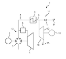
- Figure 1 shows an embodiment of an inventive arrangement 1 for cooling a rotary electric machine 2 in the form of a turbo-generator using a cooling fluid.
- the arrangement 1 is for cooling the rotating electric machine 2 of the rotating electrical Machine 2 can be connected in terms of flow. Furthermore, the arrangement 1 for producing the cooling fluid in the form of cooled ambient air is set up.
- the arrangement 1 has a compressor 3 configured for compressing ambient air.
- the compressor 3 is mechanically coupled to a turbine 4 of a gas turbine 5 and the rotary electric machine 2 and is driven via the turbine 4.
- the gas turbine 5 further has a combustion chamber 6.
- the ambient air is sucked in by the compressor 3 and compressed.
- a compressor 3 therefore, a compressor 3 of a mechanically coupled to the rotating electric machine 2 to be cooled gas turbine 5 is used.
- the arrangement 1 furthermore comprises a heat exchanger 8 arranged downstream of the compressor 3 for cooling compressed ambient air to ambient temperature, downstream of the compressor 3 via a line 7 and designed as an air cooler.
- the compressor 3 is fluidly connected to the turbine 4 via the line 7 and the combustion chamber 6.
- the arrangement 1 furthermore comprises a decompression device 10 which is arranged downstream of the heat exchanger 8 via a line 9 for the purpose of decompressing cooled ambient air to ambient pressure.
- the decompression device 10 can be connected in terms of flow technology to the rotating electrical machine 2.
- the decompression device 10 is formed by an expansion valve 11.
- the decompression device 10 is formed by an expansion turbine 12.
- the expansion turbine 12 is mechanically coupled to another generator 13 for generating electrical energy.
- a cooling fluid for example in the form of cooled ambient air, which is fed to the rotating electric machine 2 to be cooled.
- the arrangement 1 not shown in detail, arranged on the rotating electric machine 2 cooling lines, on the cooled ambient air targeted specific sections of the rotary electric machine 2 can be fed.
Landscapes
- Engineering & Computer Science (AREA)
- Power Engineering (AREA)
- Motor Or Generator Cooling System (AREA)
Priority Applications (1)
| Application Number | Priority Date | Filing Date | Title |
|---|---|---|---|
| EP20130185955 EP2854261A1 (fr) | 2013-09-25 | 2013-09-25 | Procédé destiné au refroidissement d'une machine électrique rotative |
Applications Claiming Priority (1)
| Application Number | Priority Date | Filing Date | Title |
|---|---|---|---|
| EP20130185955 EP2854261A1 (fr) | 2013-09-25 | 2013-09-25 | Procédé destiné au refroidissement d'une machine électrique rotative |
Publications (1)
| Publication Number | Publication Date |
|---|---|
| EP2854261A1 true EP2854261A1 (fr) | 2015-04-01 |
Family
ID=49253154
Family Applications (1)
| Application Number | Title | Priority Date | Filing Date |
|---|---|---|---|
| EP20130185955 Withdrawn EP2854261A1 (fr) | 2013-09-25 | 2013-09-25 | Procédé destiné au refroidissement d'une machine électrique rotative |
Country Status (1)
| Country | Link |
|---|---|
| EP (1) | EP2854261A1 (fr) |
Citations (2)
| Publication number | Priority date | Publication date | Assignee | Title |
|---|---|---|---|---|
| JPS5925034A (ja) * | 1982-08-04 | 1984-02-08 | Toshiba Corp | 発電装置 |
| WO1994022205A1 (fr) * | 1993-03-18 | 1994-09-29 | Solar Turbines Incorporated | Systeme de refroidissement de machines electriques |
-
2013
- 2013-09-25 EP EP20130185955 patent/EP2854261A1/fr not_active Withdrawn
Patent Citations (2)
| Publication number | Priority date | Publication date | Assignee | Title |
|---|---|---|---|---|
| JPS5925034A (ja) * | 1982-08-04 | 1984-02-08 | Toshiba Corp | 発電装置 |
| WO1994022205A1 (fr) * | 1993-03-18 | 1994-09-29 | Solar Turbines Incorporated | Systeme de refroidissement de machines electriques |
Similar Documents
| Publication | Publication Date | Title |
|---|---|---|
| WO2015193016A1 (fr) | Refroidissement de générateur de turbine à gaz | |
| EP1624155A1 (fr) | Turbine à vapeur et procédé d'opération d'une turbine à vapeur | |
| EP3033825B1 (fr) | Dispositif de déviation d'au moins une partie d'un fluide de refroidissement s'écoulant dans un espace intercalaire disposé entre un rotor et un stator d'une machine électrique rotative | |
| WO2014191157A2 (fr) | Pompe à chaleur équipée d'une première machine thermique à énergie fluidique et d'une seconde machine thermique à énergie fluide montées en circuit | |
| EP3476012B1 (fr) | Unité de bague collectrice comprenant un segment d'isolant de ventilateur | |
| CH701999A2 (de) | Dampfturbine mit Kühlung der Dampfturbinenlaufräder. | |
| DE102012220188B4 (de) | Integrierter ORC-Prozess an zwischengekühlten Kompressoren zur Erhöhung des Wirkungsgrades und Verringerung der erforderlichen Antriebsleistung durch Nutzung der Abwärme | |
| DE102013210255A1 (de) | Vorrichtung sowie eine solche umfassendes Antriebssystem, insbesondere für Schiffe | |
| WO2008031810A2 (fr) | installation de compression | |
| DE102012220559A1 (de) | Kühlung für elektrische Generatoren | |
| DE102014223527A1 (de) | Kühlung eines axialen Endbereichs eines Stators einer rotierenden elektrischen Maschine | |
| EP1937942B1 (fr) | Centrale à vapeur et procédé pour réaménager une centrale à vapeur | |
| DE102012221303A1 (de) | Antriebseinrichtung mit einer Brennstoffzelle und einem Abgasturbolader | |
| EP2955601A1 (fr) | Refroidissement d'un machine électrique tournante | |
| EP2854261A1 (fr) | Procédé destiné au refroidissement d'une machine électrique rotative | |
| EP2911276A1 (fr) | Circuit de refroidissement comprenant au moins deux fluides de refroidissement pour machine électrique | |
| EP3216115B1 (fr) | Procédé de refroidissement d'un générateur | |
| DE102013020426A1 (de) | Aktive Kühlung einer elektrischen Maschine im Antriebsstrang eines Fahrzeugs | |
| WO2014072341A2 (fr) | Système de refroidissement pour transducteur électromécanique | |
| DE19505388B4 (de) | Luftgekühlte rotierende elektrische Maschine | |
| EP2101043B1 (fr) | Procédé de chauffage d'une turbine à vapeur | |
| EP3058642B1 (fr) | Elément de guidage de ventilateur pour machine électrique | |
| WO2015036082A1 (fr) | Système de pile à combustible | |
| EP3775503B1 (fr) | Dispositif et procédé de fourniture de la chaleur, du froid et/ou de l'énergie électrique | |
| EP2454801B1 (fr) | Générateur électrique |
Legal Events
| Date | Code | Title | Description |
|---|---|---|---|
| PUAI | Public reference made under article 153(3) epc to a published international application that has entered the european phase |
Free format text: ORIGINAL CODE: 0009012 |
|
| 17P | Request for examination filed |
Effective date: 20130925 |
|
| AK | Designated contracting states |
Kind code of ref document: A1 Designated state(s): AL AT BE BG CH CY CZ DE DK EE ES FI FR GB GR HR HU IE IS IT LI LT LU LV MC MK MT NL NO PL PT RO RS SE SI SK SM TR |
|
| AX | Request for extension of the european patent |
Extension state: BA ME |
|
| STAA | Information on the status of an ep patent application or granted ep patent |
Free format text: STATUS: THE APPLICATION IS DEEMED TO BE WITHDRAWN |
|
| 18D | Application deemed to be withdrawn |
Effective date: 20151002 |