EP2854397B1 - Dispositif d'administration de caméra de surveillance, procédé d'administration de caméra de surveillance et programme - Google Patents
Dispositif d'administration de caméra de surveillance, procédé d'administration de caméra de surveillance et programme Download PDFInfo
- Publication number
- EP2854397B1 EP2854397B1 EP13794573.9A EP13794573A EP2854397B1 EP 2854397 B1 EP2854397 B1 EP 2854397B1 EP 13794573 A EP13794573 A EP 13794573A EP 2854397 B1 EP2854397 B1 EP 2854397B1
- Authority
- EP
- European Patent Office
- Prior art keywords
- camera
- surveillance
- cameras
- map
- link
- Prior art date
- Legal status (The legal status is an assumption and is not a legal conclusion. Google has not performed a legal analysis and makes no representation as to the accuracy of the status listed.)
- Active
Links
Images





Classifications
-
- H—ELECTRICITY
- H04—ELECTRIC COMMUNICATION TECHNIQUE
- H04N—PICTORIAL COMMUNICATION, e.g. TELEVISION
- H04N7/00—Television systems
- H04N7/18—Closed-circuit television [CCTV] systems, i.e. systems in which the video signal is not broadcast
- H04N7/181—Closed-circuit television [CCTV] systems, i.e. systems in which the video signal is not broadcast for receiving images from a plurality of remote sources
-
- G—PHYSICS
- G08—SIGNALLING
- G08B—SIGNALLING SYSTEMS, e.g. PERSONAL CALLING SYSTEMS; ORDER TELEGRAPHS; ALARM SYSTEMS
- G08B13/00—Burglar, theft or intruder alarms
- G08B13/18—Actuation by interference with heat, light, or radiation of shorter wavelength; Actuation by intruding sources of heat, light, or radiation of shorter wavelength
- G08B13/189—Actuation by interference with heat, light, or radiation of shorter wavelength; Actuation by intruding sources of heat, light, or radiation of shorter wavelength using passive radiation detection systems
- G08B13/194—Actuation by interference with heat, light, or radiation of shorter wavelength; Actuation by intruding sources of heat, light, or radiation of shorter wavelength using passive radiation detection systems using image scanning and comparing systems
- G08B13/196—Actuation by interference with heat, light, or radiation of shorter wavelength; Actuation by intruding sources of heat, light, or radiation of shorter wavelength using passive radiation detection systems using image scanning and comparing systems using television cameras
- G08B13/19639—Details of the system layout
- G08B13/19645—Multiple cameras, each having view on one of a plurality of scenes, e.g. multiple cameras for multi-room surveillance or for tracking an object by view hand-over
-
- G—PHYSICS
- G08—SIGNALLING
- G08B—SIGNALLING SYSTEMS, e.g. PERSONAL CALLING SYSTEMS; ORDER TELEGRAPHS; ALARM SYSTEMS
- G08B13/00—Burglar, theft or intruder alarms
- G08B13/18—Actuation by interference with heat, light, or radiation of shorter wavelength; Actuation by intruding sources of heat, light, or radiation of shorter wavelength
- G08B13/189—Actuation by interference with heat, light, or radiation of shorter wavelength; Actuation by intruding sources of heat, light, or radiation of shorter wavelength using passive radiation detection systems
- G08B13/194—Actuation by interference with heat, light, or radiation of shorter wavelength; Actuation by intruding sources of heat, light, or radiation of shorter wavelength using passive radiation detection systems using image scanning and comparing systems
- G08B13/196—Actuation by interference with heat, light, or radiation of shorter wavelength; Actuation by intruding sources of heat, light, or radiation of shorter wavelength using passive radiation detection systems using image scanning and comparing systems using television cameras
- G08B13/19602—Image analysis to detect motion of the intruder, e.g. by frame subtraction
- G08B13/19608—Tracking movement of a target, e.g. by detecting an object predefined as a target, using target direction and or velocity to predict its new position
-
- G—PHYSICS
- G08—SIGNALLING
- G08B—SIGNALLING SYSTEMS, e.g. PERSONAL CALLING SYSTEMS; ORDER TELEGRAPHS; ALARM SYSTEMS
- G08B13/00—Burglar, theft or intruder alarms
- G08B13/18—Actuation by interference with heat, light, or radiation of shorter wavelength; Actuation by intruding sources of heat, light, or radiation of shorter wavelength
- G08B13/189—Actuation by interference with heat, light, or radiation of shorter wavelength; Actuation by intruding sources of heat, light, or radiation of shorter wavelength using passive radiation detection systems
- G08B13/194—Actuation by interference with heat, light, or radiation of shorter wavelength; Actuation by intruding sources of heat, light, or radiation of shorter wavelength using passive radiation detection systems using image scanning and comparing systems
- G08B13/196—Actuation by interference with heat, light, or radiation of shorter wavelength; Actuation by intruding sources of heat, light, or radiation of shorter wavelength using passive radiation detection systems using image scanning and comparing systems using television cameras
- G08B13/19678—User interface
- G08B13/19691—Signalling events for better perception by user, e.g. indicating alarms by making display brighter, adding text, creating a sound
- G08B13/19693—Signalling events for better perception by user, e.g. indicating alarms by making display brighter, adding text, creating a sound using multiple video sources viewed on a single or compound screen
-
- G—PHYSICS
- G08—SIGNALLING
- G08B—SIGNALLING SYSTEMS, e.g. PERSONAL CALLING SYSTEMS; ORDER TELEGRAPHS; ALARM SYSTEMS
- G08B13/00—Burglar, theft or intruder alarms
- G08B13/18—Actuation by interference with heat, light, or radiation of shorter wavelength; Actuation by intruding sources of heat, light, or radiation of shorter wavelength
- G08B13/189—Actuation by interference with heat, light, or radiation of shorter wavelength; Actuation by intruding sources of heat, light, or radiation of shorter wavelength using passive radiation detection systems
- G08B13/194—Actuation by interference with heat, light, or radiation of shorter wavelength; Actuation by intruding sources of heat, light, or radiation of shorter wavelength using passive radiation detection systems using image scanning and comparing systems
- G08B13/196—Actuation by interference with heat, light, or radiation of shorter wavelength; Actuation by intruding sources of heat, light, or radiation of shorter wavelength using passive radiation detection systems using image scanning and comparing systems using television cameras
- G08B13/19639—Details of the system layout
- G08B13/19641—Multiple cameras having overlapping views on a single scene
Definitions
- the present technique relates to surveillance camera management devices, surveillance camera management methods, and programs, and more particularly, to a surveillance camera management device that manages surveillance cameras that monitor floors, an urban area, or the like.
- Video surveillance systems for security, marketing, or the like have been installed in hotels, buildings, convenience stores, and the likes. With such surveillance systems, operations are being conducted everywhere to monitor how suspicious individuals move or how customers move on the floor. In an application for tracking a person between cameras, advance calibration of positional relationship on the floor is essential in increasing accuracy. However, if such calibration needs to be conducted manually, the load on the surveillance agent becomes very large.
- Patent Document 1 discloses a technique for estimating the link relations between cameras based on the frequency distributions of the appearance times and the disappearance times of all the surveillance objects extracted by the respective cameras.
- Patent Document 2 discloses a technique for calculating similarities between objects based on color features or the like to determine whether the objects are the same person, and generating the link relations between cameras, for example.
- US 2008/088706 A1 discloses a display of feeds from several cameras that are selected based on temporal and / or spatial relation to a main camera. The average difference between several different focal points of a pair of cameras is used to determine whether or not the cameras are associated and thus images therefrom are displayed together.
- GB2384128 discloses a surveillance camera management method to project surveillance areas of a plurality of cameras onto a map and follow a target in the map.
- the object of the present technique is to accurately and readily acquire information about link relations between cameras.
- the concept of the present technique lies in a surveillance camera management device according to claim 1.
- the cameras are managed on the map.
- the surveillance areas of cameras registered on a map having a surveillance region set thereon are projected onto the map by the surveillance area projection unit.
- This projection is conducted based on parameters such as the installation heights, the elevation angles, and the rotation angles of the respective cameras, and further on parameters such as the focal lengths, the image coordinate centers, the lens strain coefficients, and the image coordinate aspect ratios of the respective cameras, which are set in advance.
- the shortest path search unit searches for the shortest paths between the cameras registered on the map.
- the camera link determination unit determines links between the cameras based on the surveillance areas of the cameras projected on the map and the shortest paths between the cameras detected on the map.
- the link determination unit determines that the first camera and the second camera are linked to each other.
- links between cameras are determined based on the surveillance areas of the cameras projected onto a map and the shortest paths between the cameras detected on the map, and information about the link relations between the cameras can be accurately and readily acquired.
- this technique does not require a surveillance object to walk around so as to be actually captured by all the cameras, and can be applied even in a case where there is congestion in the surveillance region. Accordingly, the load on the user can be reduced.
- the link determination unit may further calculate the link distance between cameras determined to be linked to each other, for example.
- This link distance is information useful for obtaining a reference time to be required between disappearance of a surveillance object from the surveillance area of a certain camera and appearance of the surveillance object in front of a camera linked to the certain camera, for example.
- the link determination unit may determine the link distance between the first camera and the second camera to be the distance from the exit of the surveillance area of the first camera to the second camera or the entrance of the surveillance area of the second camera, for example.
- the link determination unit may determine the link distance between the first camera and the second camera to be the distance from the registered position of the first camera to the second camera or the entrance of the surveillance area of the second camera, for example.
- the surveillance area projection unit may divide the overlap region between the respective cameras, for example.
- the surveillance area projection unit may divide the overlap region between the cameras, taking into account projection accuracy.
- the surveillance object shown in a larger size and in greater detail in a camera image can be displayed in the form of a pop-up, for example.
- the surveillance camera management device may further include an output camera image select unit that selects output camera images from among camera images based on an inter- camera link relation acquired by the link determination unit, for example.
- the output camera image select unit may select camera images of a predetermined number of cameras linked to the predetermined camera as the camera images to be output to sub-monitors, for example. In this case, even if the number of monitors is small, camera images for tracking the surveillance object can be efficiently displayed.
- Fig. 1 shows an example of a surveillance camera system 10 as an embodiment.
- This surveillance camera system 10 includes cameras 11-1 through 11-N, a switch unit 12, a monitor unit 13, and a surveillance camera management unit 14.
- the cameras 11-1 through 11-N are surveillance cameras that are placed on floors, in an urban area, or the like.
- the switch unit 12 selectively extracts a predetermined number of camera images from among camera images obtained with the cameras 11-1 through 11-N, and supplies the extracted camera images to the monitor unit 13.
- the monitor unit 13 includes a predetermined number of monitors, such as one main monitor and sub-monitors, and displays a camera image.
- the surveillance camera management unit 14 acquires inter-camera link relation information, and controls operation of the switch unit 12 and the like based on the link relation information and the like.
- Fig. 2 shows an example structure of the surveillance camera management unit 14.
- the surveillance camera management unit 14 manages the cameras (surveillance cameras) 11-1 through 11-N on a scaled-down map showing the above mentioned floors, the above mentioned urban area, or the like.
- the surveillance camera management unit 14 includes a surveillance region setting unit 101, a camera parameter setting unit 102, a surveillance region/camera parameter storage unit 103, a surveillance area projection unit 104, a shortest path search unit 105, and an inter-camera link determination unit 106.
- the surveillance camera management unit 14 also includes an inter-camera link relation storage unit 107, an output camera image select unit 108, and a camera image output unit 109.
- the surveillance region setting unit 101 sets a surveillance region on the map based on a user operation.
- Fig. 3(a) shows an example of a map displayed on the monitor (not shown) of the surveillance camera management unit 14.
- Fig. 3(b) shows an example of a surveillance region that is set on the map. In this case, the surveillance region that is set excludes obstruction regions such as walls.
- the camera parameter setting unit 102 sets camera parameters of the cameras (surveillance cameras) 11-1 through 11-N based on user operations.
- the camera parameters are information for projecting the surveillance areas of the respective cameras onto the map.
- the camera parameters include information about the installation positions of the respective cameras.
- the camera parameters also include information such as the installation heights, the elevation angles, and the rotation angles of the respective cameras, and further include information such as the focal lengths, the image coordinate centers, the lens strain coefficients, and the image coordinate aspect ratios of the respective cameras.
- the surveillance region/camera parameter storage unit 103 stores the information about the surveillance region that is set by the surveillance region setting unit 101, and the camera parameters of the respective cameras that are set by the camera parameter setting unit 102.
- the surveillance area projection unit 104 projects the surveillance areas of the respective cameras onto the map based on the surveillance region and the camera parameters of the respective cameras.
- the surveillance area projection unit 104 registers the respective cameras on the map based on the installation position information about the respective cameras.
- the surveillance area projection unit 104 also determines surveillance areas to be projected onto the map based on other information about the respective cameras.
- Fig. 3(c) shows an example of the respective cameras registered on the map and the respective projected surveillance areas.
- the surveillance area ARa of the camera A, the surveillance area ARb of the camera B, the surveillance area ARc of the camera C, the surveillance area ARd of the camera D, and the surveillance area ARe of the camera E are projected.
- the surveillance area ARa of the camera A and the surveillance area ARb of the camera B are in contact with each other and are joined together.
- these surveillance areas ARa and ARb are determined by dividing a surveillance area overlap region between the respective cameras.
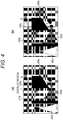
- Fig. 4(a) shows a situation where there is an overlap region between the surveillance area ARa of the camera A and the surveillance area ARb of the camera B
- Fig. 4(b) shows a situation where the overlap region has been divided as shown in Fig. 3(c) .
- the surveillance area projection unit 104 assigns each of the pixels included in the overlap region to the surveillance area ARa of the camera A or the surveillance area ARb of the camera B, taking into account projection accuracy, for example. Specifically, pixels in which the projection accuracy of the camera A is higher are assigned to the surveillance area ARa of the camera A, and pixels in which the projection accuracy of the camera B is higher are assigned to the surveillance area ARb of the camera B.
- the dividing of the overlap region may be performed simply by assigning each pixel to the closer camera surveillance area in terms of distance. Not only an overlap region between the surveillance areas of two cameras but also an overlap region among the surveillance areas of three or more cameras can be divided in the same manner as above.
- the shortest path search unit 105 searches for the shortest paths between the cameras registered on the map.
- the shortest path search unit 105 uses a conventional technique such as Dijkstra's method.
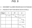
- Fig. 5 shows examples of weights between pixels that form paths.
- "o” represents a pixel in a surveillance region or a movement-allowed region such as a passage.
- ⁇ represents a pixel in a surveillance region or a movement-prohibited region such as a wall. It should be noted that " ⁇ ” is set at a sufficiently large value.
- Fig. 3(d) shows an example of the detected shortest paths between the camera A and the other cameras.
- the inter-camera link determination unit 106 determines links between the cameras based on the surveillance areas of the cameras projected by the surveillance area projection unit 104 and the shortest paths between the cameras detected by the shortest path search unit 105. For example, where the two cameras to be subjected to link determination are a first camera and a second camera, the link determination is performed as described below.
- the two cameras are determined to be linked if the shortest path reaches the second camera or the surveillance area of the second camera with no contact with a surveillance area other than the surveillance area of the first camera.
- the shortest path enters the surveillance area of the surveillance area ARb of the camera B immediately after exiting the surveillance area ARa of the camera A. Accordingly, the camera A and the camera B are determined to be linked.
- link determination on the camera A and the camera C when the shortest path is traced from the camera A to the camera C, the shortest path directly reaches the camera C from the camera A with no contact with the surveillance areas of the respective cameras. Accordingly, the camera A and the camera C are determined to be liked.
- link determination on the camera A and the camera D when the shortest path from the camera A to the camera D is traced, the shortest path enters the surveillance area of the camera D after exiting the surveillance area ARa of the camera A. Accordingly, the camera A and the camera D are determined to be linked.
- the inter-camera link determination unit 106 determines the two cameras not to be linked if the shortest path reaches the second camera or the surveillance area of the second camera after coming into contact with a surveillance area that is neither the surveillance area of the first camera nor the surveillance area of the second camera. For example, in the example shown in Fig. 3(d) , when the shortest path from the camera A to the camera E is traced in link determination on the camera A and the camera E, the shortest path reaches the camera E after exiting the surveillance area ARa of the camera A and coming into contact with the surveillance area of the camera D. Accordingly, the camera A and the camera E are determined not to be linked.
- the inter-camera link determination unit 106 further calculates the link distances between the cameras determined to be linked. For example, where the two cameras determined to be linked are the first camera and the second camera, the link distance is calculated as described below.
- the distance from the exit of the surveillance area of the first camera to the second camera or the entrance of the surveillance area of the second camera is set as the link distance between the first camera and the second camera.
- the distance from the registered position of the first camera to the second camera or the entrance of the surveillance area of the second camera is set as the link distance between the first camera and the second camera.
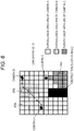
- Fig. 6 shows a specific example of a link distance calculation.
- there are ten pixels in the horizontal direction and ten pixels in the vertical direction and the link distance between the camera A and the camera B is to be calculated.
- the shortest path enters the surveillance area ARb of the camera B immediately after exiting the surveillance area ARa of the camera A, and accordingly, the link distance is calculated to be "0".
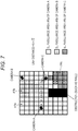
- Fig. 7 shows another specific example of a link distance calculation.
- the link distance between the camera A and the camera C is to be calculated.
- the shortest path extends six pixels in the horizontal direction from the registered position of the camera A and further extends one pixel in a diagonal direction to reach the camera C. Accordingly, the link distance is calculated as "6 + ⁇ 2".
- Fig. 8 shows yet another specific example of a link distance calculation.
- the link distance between the camera A and the camera C is to be calculated.
- the shortest path extends three pixels in the horizontal direction from the registered position of the camera A and further extends two pixels in a diagonal direction to reach the surveillance area of the camera C. Accordingly, the link distance is calculated as "3 + 2 ⁇ 2".
- the inter-camera link relation storage unit 107 stores the link relation information and the inter-camera link distance information obtained by the camera link determination unit 106.
- Fig. 9 shows an example of the link relation information and the link distance information corresponding to the example shown in Fig. 3(c) .
- a through E in circles represent the respective cameras, and each two cameras connected by a line are linked to each other.
- the link distances are denoted by a through e.
- the inter-camera link relation information stored in the inter-camera link relation storage unit 107 is used as the information for selecting output camera images from among camera images of the cameras as described later, for example.
- the link distance information stored in the inter-camera link relation storage unit 107 about the cameras determined to be linked is the information useful for obtaining a reference time to be required between disappearance of a surveillance object from the surveillance area of a certain camera and appearance of the surveillance object in the surveillance area of a camera linked to the certain camera.
- the output camera image select unit 108 selects output camera images from among images of the cameras.
- the camera image output unit 109 outputs a control signal to the switch unit 12 so that the camera images selected by the output camera image select unit 108 are supplied to the monitor unit 13 (see Fig. 1 ).
- the output camera image select unit 108 selects camera images of a predetermined number of cameras linked to the predetermined camera as the camera images to be output to the sub-monitors.
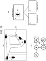
- the surveillance object WN is located in the surveillance area of the camera E. Therefore, the output camera image select unit 108 selects the camera image of the camera E as the camera image to be output to the main monitor, as shown in Fig. 10(c) .
- the camera E, the camera B, and the camera D are linked as shown in Fig. 10(b) , and therefore, the output camera image select unit 108 selects the camera images of the camera B and the camera D as the camera images to be output to the sub-monitors as shown in Fig. 10(c) . Since the surveillance object WN does not exist in the surveillance areas of the camera B and the camera D in this case, the camera images of these cameras do not show the surveillance object WN.
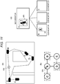
- the surveillance object WN is located in the surveillance area of the camera A. Therefore, the output camera image select unit 108 selects the camera image of the camera A as the camera image to be output to the main monitor, as shown in Fig. 11(c) .
- the camera A, the camera B, the camera C, and the camera D are linked as shown in Fig. 11(b) , and therefore, the output camera image select unit 108 selects the camera images of the camera B, the camera C, and the camera D as the camera images to be output to the sub-monitors as shown in Fig. 11(c) .
- the camera image of the camera B also shows the surveillance object WN as shown in Fig. 11(c) .
- the camera image of the camera A displayed on the main monitor shows the surveillance object WN in a larger size and in greater detail than in the camera image of the camera B displayed on a sub-monitor. That is, since the dividing process is performed, the camera image of the camera having the surveillance area in which the surveillance object WN exists is output to the main monitor, so that a camera image showing the surveillance object WN in a larger size and in greater detail can be displayed as a pop-up on the main monitor.
- the surveillance region setting unit 101 sets a surveillance region on the map based on a user operation (see Fig. 3(b) ). Information about the surveillance region that is set in this manner is stored into the surveillance region/camera parameter storage unit 103.
- the camera parameter setting unit 102 Based on user operations, the camera parameter setting unit 102 also sets the camera parameters (information such as the installation positions of the respective cameras, the installation heights of the respective cameras, the elevation angles, the rotation angles, the focal lengths of the respective cameras, the image coordinate centers, the lens strain coefficients, and the image coordinate aspect ratios) of the cameras (surveillance cameras) 11-1 through 11-N.
- the camera parameters of the respective cameras that are set in this manner are stored into the surveillance region/camera parameter storage unit 103.
- the surveillance area projection unit 104 registers the respective cameras on the map and projects the respective surveillance areas onto the map based on the surveillance region and the camera parameters (see Fig. 3(c) ).
- the respective cameras are registered on the map based on the information about the installation positions of the respective cameras, and the surveillance areas to be projected onto the map are determined based on the other information about the respective cameras.
- the shortest path search unit 105 searches for the shortest paths between the cameras registered on the map (see Fig. 3(d) ).
- the inter-camera link determination unit 106 determines links between cameras based on the surveillance areas of the cameras projected on the map and the shortest paths between the cameras detected on the map.
- the inter-camera link determination unit 106 also calculates the link distances between the cameras determined to be linked.
- the link relation information and the link distance information obtained by the inter-camera link determination unit 106 are stored into the inter-camera link relation storage unit 107.
- the output camera image select unit 108 selects output camera images from among camera images. For example, when a camera image of a predetermined camera showing the surveillance object is selected as the camera image to be output to the main monitor, camera images of a predetermined number of cameras linked to the predetermined camera are selected as the camera images to be output to the sub-monitors.
- the camera image output unit 109 outputs a control signal to the switch unit 12 so that the camera images selected by the output camera image select unit 108 are supplied to the monitor unit 13.
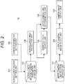
- the flowchart in Fig. 12 shows an example flow of a process operation to be performed until the link relation information and the link distance information about the respective cameras are stored into the surveillance region/camera parameter storage unit 103 in the surveillance camera management unit 14 shown in Fig. 2 .
- step ST1 the surveillance camera management unit 14 starts the process, and then moves on to the procedure of step ST2.
- step ST2 the surveillance camera management unit 14 sets a surveillance region on the map with the surveillance region setting unit 101 based on a user operation.
- step ST3 the surveillance camera management unit 14 registers the respective cameras on the map based on the installation position information that is set by the camera parameter setting unit 102 about the respective cameras.
- step ST4 the surveillance camera management unit 14 projects the surveillance areas of the respective cameras onto the map based on the information such as the installation heights of the respective cameras, the elevation angles, the rotation angles, the focal lengths of the respective cameras, the image coordinate centers, the lens strain coefficients, and the image coordinate aspect ratios that are set by the camera parameter setting unit 102. If there is an overlap region between the surveillance areas of the respective cameras projected onto the map in step ST4, the surveillance camera management unit 14 in step ST5 divides the overlap region between the surveillance areas of the respective cameras, taking into account projection accuracy, for example.
- step ST6 the surveillance camera management unit 14 searches for the shortest paths between cameras among the cameras registered on the map.
- step ST7 the surveillance camera management unit 14 determines links between cameras by using the detected shortest paths between the cameras and the projected surveillance areas of the respective cameras, and acquires link relation information.
- step ST8 the surveillance camera management unit 14 calculates the link distances between the linked cameras.
- step ST9 the surveillance camera management unit 14 stores the link relation information acquired in step ST7 and the link distance information acquired in step ST8 into the inter-camera link relation storage unit 107. After the procedure of step ST9, the surveillance camera management unit 14 ends the process in step ST10.
- the surveillance camera management unit 14 determines links between cameras based on the surveillance areas of the cameras projected on the map and the shortest paths between the cameras detected on the map. Accordingly, the information about the link relations between the cameras can be accurately and readily acquired. Unlike a conventional technique by which link relation information is manually acquired, this technique does not require a surveillance object to walk around so as to be actually captured by all the cameras, and can be applied even in a case where there is congestion in the surveillance region. Accordingly, the load on the user can be reduced.
- the surveillance camera management unit 14 divides the overlap region between the respective cameras. Accordingly, a surveillance object shown in a larger size and in greater detail in a camera image can be displayed in the form of a pop-up.
- the surveillance camera management unit 14 selects output camera images from among camera images based on inter-camera link relations. For example, when a camera image of a predetermined camera is selected as the camera image to be output to the main monitor, camera images of a predetermined number of cameras linked to the predetermined camera are selected as the camera images to be output to the sub-monitors. Accordingly, even if the number of monitors is small, camera images for tracking a surveillance object can be efficiently displayed.
- the cameras 11-1 through 11-N are connected to the switch unit 12 by wires in the above described embodiment, those cameras may be wirelessly connected to the switch unit 12.
- the surveillance camera management unit 14 may remotely control the heights, the elevation angles, and the rotation angles of the respective cameras. In such a case, the surveillance camera management unit 14 updates the surveillance areas of the respective areas or the like every time there is a change in those parameters.
Landscapes
- Engineering & Computer Science (AREA)
- Physics & Mathematics (AREA)
- General Physics & Mathematics (AREA)
- Multimedia (AREA)
- Computer Vision & Pattern Recognition (AREA)
- Human Computer Interaction (AREA)
- Signal Processing (AREA)
- Closed-Circuit Television Systems (AREA)
- Alarm Systems (AREA)
- Studio Devices (AREA)
Claims (7)
- Dispositif de gestion de caméras de surveillance (14) comprenant :une unité de projection de zones de surveillance (104) configurée pour projeter des zones de surveillance d'une pluralité de caméras (11-1 - 11-N) sur une carte illustrant une région de surveillance, la pluralité de caméras étant enregistrée sur la carte ;une unité de recherche du trajet le plus court (105) configurée pour rechercher un trajet le plus court entre une première caméra et une deuxième caméra de la pluralité de caméras enregistrée sur la carte ;une unité de détermination de liaison (106) configurée pour déterminer une liaison entre la première caméra et la deuxième caméra en fonction des zones de surveillance (ARa-ARe) des première et deuxième caméras projetées sur la carte et du trajet le plus court entre les première et deuxième caméras détectées sur la carte, dans lequelquand le trajet le plus court tracé de la première caméra à la deuxième caméra atteint la deuxième caméra ou la zone de surveillance de la deuxième caméra sans entrer en contact avec une zone de surveillance d'une autre caméra autre que la zone de surveillance de la première caméra, l'unité de détermination de liaison est configurée pour déterminer que la première caméra et la deuxième caméra sont reliées l'une à l'autre ; etune unité de sélection d'image de caméra de sortie (108) configurée pour sélectionner une image de caméra de sortie parmi une pluralité d'images de caméra en fonction d'une relation de liaison entre caméras acquise par l'unité de détermination de liaison, dans lequel quand une zone de chevauchement existe entre les zones de surveillance des caméras sur la carte, l'unité de projection de zone de surveillance est configurée pour diviser la région de chevauchement entre les caméras.
- Dispositif de gestion de caméras de surveillance selon la revendication 1, dans lequel l'unité de détermination de liaison est configurée pour calculer une distance de liaison du trajet le plus court tracé de la première caméra à la deuxième caméra, la distance de liaison étant une information servant à obtenir un temps de référence entre la disparition d'un objet de surveillance de la zone de surveillance de l'une de la première caméra ou deuxième caméra et l'apparition de l'objet de surveillance dans la zone de surveillance de l'autre de la première caméra ou deuxième caméra.
- Dispositif de gestion de caméras de surveillance selon la revendication 2, dans lequel,
quand le trajet le plus court tracé de la première caméra à la deuxième caméra déterminées être reliées l'une à l'autre atteint la deuxième caméra ou la zone de surveillance de la deuxième caméra après être sorti de la zone de surveillance de la première caméra, l'unité de détermination de liaison est configurée pour calculer la distance de liaison entre la première caméra et la deuxième caméra comme une distance depuis la sortie de la zone de surveillance de la première caméra jusqu'à la deuxième caméra ou l'entrée dans la zone de surveillance de la deuxième caméra, et
quand le trajet le plus court tracé de la première caméra à la deuxième caméra déterminées être reliées l'une à l'autre atteint la deuxième caméra ou la zone de surveillance de la deuxième caméra à partir de la première caméra sans entrer en contact avec la zone de surveillance de la première caméra, l'unité de détermination de liaison est configurée pour calculer la distance de liaison entre la première caméra et la deuxième caméra comme une distance à partir d'une position enregistrée de la première caméra sur la carte jusqu'à une position enregistrée de la deuxième caméra sur la carte ou l'entrée dans la zone de surveillance de la deuxième caméra. - Dispositif de gestion de caméras de surveillance selon la revendication 1, dans lequel
l'unité de projection de zone de surveillance est adaptée pour diviser la région de chevauchement entre les caméras, en tenant compte d'une précision de projection. - Dispositif de gestion de caméras de surveillance selon la revendication 1, dans lequel,
lors de la sélection d'une image de caméra d'une caméra prédéterminée comme image de caméra à délivrer à un contrôleur principal, l'unité de sélection d'image de caméra de sortie est adaptée pour sélectionner des images de caméra d'un nombre prédéterminé de caméras reliées à la caméra prédéterminée comme images de caméra à délivrer à des sous-contrôleurs. - Procédé de gestion de caméras de surveillance comprenant :une étape de projection de zones de surveillance consistant à projeter des zones de surveillance (ARa-ARe) d'une pluralité de caméras (11-1 - 11-N) sur une carte illustrant une région de surveillance, la pluralité de caméras étant enregistrée sur la carte ;une étape de recherche du trajet le plus court consistant à rechercher un trajet le plus court entre une première caméra et une deuxième caméra de la pluralité de caméras enregistrée sur la carte ;une étape de détermination de liaison consistant à déterminer une liaison entre la première caméra et la deuxième caméra en fonction des zones de surveillance des première et deuxième caméras projetées sur la carte et du trajet le plus court entre les première et deuxième caméras détectées sur la carte, dans lequel quand le trajet le plus court tracé de la première caméra à la deuxième caméra atteint la deuxième caméra ou la zone de surveillance de la deuxième caméra sans entrer en contact avec une zone de surveillance d'une autre caméra autre que la zone de surveillance de la première caméra, l'étape de détermination de liaison détermine que la première caméra et la deuxième caméra sont reliées l'une à l'autre ; etune étape de sélection d'image de caméra de sortie consistant à sélectionner une image de caméra de sortie parmi une pluralité d'images de caméra en fonction d'une relation de liaison entre caméras acquise par l'étape de détermination de liaison, le procédé comprenant en outre quand il existe une zone de chevauchement entre les zones de surveillance des caméras sur la carte, la division de la région de chevauchement entre les caméras.
- Programme pour amener un ordinateur à fonctionner en tant que :unité de projection de zones de surveillance (104) configurée pour projeter des zones de surveillance (ARa - ARe) d'une pluralité de caméras (11-1 - 11-N) sur une carte illustrant une région de surveillance, la pluralité de caméras étant enregistrée sur la carte ;unité de recherche du trajet le plus court (105) configurée pour rechercher un trajet le plus court entre une première caméra et une deuxième caméra de la pluralité de caméras enregistrée sur la carte ;unité de détermination de liaison (106) configurée pour déterminer une liaison entre la première caméra et la deuxième caméra en fonction des zones de surveillance des première et deuxième caméras projetées sur la carte et du trajet le plus court entre les première et deuxième caméras détectées sur la carte, dans lequelquand le trajet le plus court tracé de la première caméra à la deuxième caméra atteint la deuxième caméra ou la zone de surveillance de la deuxième caméra sans entrer en contact avec une zone de surveillance d'une autre caméra autre que la zone de surveillance de la première caméra, l'unité de détermination de liaison est configurée pour déterminer que la première caméra et la deuxième caméra sont reliées l'une à l'autre ; etunité de sélection d'image de caméra de sortie (108) configurée pour sélectionner une image de caméra de sortie parmi une pluralité d'images de caméra en fonction d'une relation de liaison entre caméras acquise par l'unité de détermination de liaison, dans lequel quand une zone de chevauchement existe entre les zones de surveillance des caméras sur la carte, l'unité de projection de zone de surveillance est configurée pour diviser la région de chevauchement entre les caméras.
Applications Claiming Priority (2)
| Application Number | Priority Date | Filing Date | Title |
|---|---|---|---|
| JP2012117277 | 2012-05-23 | ||
| PCT/JP2013/057564 WO2013175836A1 (fr) | 2012-05-23 | 2013-03-15 | Dispositif d'administration de caméra de surveillance, procédé d'administration de caméra de surveillance et programme |
Publications (3)
| Publication Number | Publication Date |
|---|---|
| EP2854397A1 EP2854397A1 (fr) | 2015-04-01 |
| EP2854397A4 EP2854397A4 (fr) | 2016-01-13 |
| EP2854397B1 true EP2854397B1 (fr) | 2020-12-30 |
Family
ID=49623540
Family Applications (1)
| Application Number | Title | Priority Date | Filing Date |
|---|---|---|---|
| EP13794573.9A Active EP2854397B1 (fr) | 2012-05-23 | 2013-03-15 | Dispositif d'administration de caméra de surveillance, procédé d'administration de caméra de surveillance et programme |
Country Status (4)
| Country | Link |
|---|---|
| US (1) | US9948897B2 (fr) |
| EP (1) | EP2854397B1 (fr) |
| JP (1) | JP6032283B2 (fr) |
| WO (1) | WO2013175836A1 (fr) |
Families Citing this family (6)
| Publication number | Priority date | Publication date | Assignee | Title |
|---|---|---|---|---|
| KR101678004B1 (ko) * | 2015-02-24 | 2016-11-21 | 주식회사세오 | 노드-링크 기반 카메라 네트워크 통합 감시 시스템 및 감시 방법 |
| KR101800130B1 (ko) * | 2016-07-15 | 2017-11-21 | 신후주식회사 | 울타리 주변 영역에서 타겟을 검출하는 방법 및 시스템 |
| JP2020079971A (ja) * | 2017-03-24 | 2020-05-28 | パナソニックIpマネジメント株式会社 | カメラ側装置、画像情報ダウンロードシステム及び画像情報ダウンロード方法 |
| AU2019374741B2 (en) | 2018-11-06 | 2023-02-02 | Motorola Solutions, Inc. | Method and system for displaying video streams |
| CN113329213A (zh) * | 2021-08-02 | 2021-08-31 | 徐州源勤电子科技有限公司 | 基于大数据的监控方法及系统 |
| JP2025038772A (ja) * | 2023-09-07 | 2025-03-19 | キヤノン株式会社 | 撮影制御装置および撮影制御方法、ならびに撮像システム |
Family Cites Families (22)
| Publication number | Priority date | Publication date | Assignee | Title |
|---|---|---|---|---|
| GB2384128A (en) | 2001-12-13 | 2003-07-16 | Invideo Ltd | Schematic mapping of surveillance area |
| JP4195991B2 (ja) * | 2003-06-18 | 2008-12-17 | パナソニック株式会社 | 監視映像モニタリングシステム、監視映像生成方法、および監視映像モニタリングサーバ |
| US20050012817A1 (en) * | 2003-07-15 | 2005-01-20 | International Business Machines Corporation | Selective surveillance system with active sensor management policies |
| KR101000699B1 (ko) | 2004-04-19 | 2010-12-10 | 엘지전자 주식회사 | 무선링크 제어계층에서의 데이터 처리방법 |
| JP4651999B2 (ja) | 2004-09-02 | 2011-03-16 | 綜合警備保障株式会社 | 監視システム、監視方法 |
| JP4587166B2 (ja) * | 2004-09-14 | 2010-11-24 | キヤノン株式会社 | 移動体追跡システム、撮影装置及び撮影方法 |
| JP4829290B2 (ja) | 2005-03-25 | 2011-12-07 | センサーマティック・エレクトロニクス・エルエルシー | インテリジェントなカメラ選択および対象追跡 |
| US20080291278A1 (en) * | 2005-04-05 | 2008-11-27 | Objectvideo, Inc. | Wide-area site-based video surveillance system |
| JP4852765B2 (ja) | 2005-08-30 | 2012-01-11 | 国立大学法人 奈良先端科学技術大学院大学 | 広域分散カメラ間の連結関係推定法および連結関係推定プログラム |
| US20080123900A1 (en) * | 2006-06-14 | 2008-05-29 | Honeywell International Inc. | Seamless tracking framework using hierarchical tracklet association |
| US8274564B2 (en) | 2006-10-13 | 2012-09-25 | Fuji Xerox Co., Ltd. | Interface for browsing and viewing video from multiple cameras simultaneously that conveys spatial and temporal proximity |
| JP4344869B2 (ja) * | 2007-02-16 | 2009-10-14 | 三菱電機株式会社 | 計測装置 |
| US8760519B2 (en) | 2007-02-16 | 2014-06-24 | Panasonic Corporation | Threat-detection in a distributed multi-camera surveillance system |
| ITMI20071016A1 (it) | 2007-05-19 | 2008-11-20 | Videotec Spa | Metodo e sistema per sorvegliare un ambiente |
| JP4976939B2 (ja) | 2007-07-04 | 2012-07-18 | 株式会社日立国際電気 | 画像処理装置 |
| US8370111B2 (en) * | 2008-03-31 | 2013-02-05 | The Boeing Company | System and method for forming optimized perimeter surveillance |
| US8488001B2 (en) * | 2008-12-10 | 2013-07-16 | Honeywell International Inc. | Semi-automatic relative calibration method for master slave camera control |
| US8180107B2 (en) * | 2009-02-13 | 2012-05-15 | Sri International | Active coordinated tracking for multi-camera systems |
| US8576235B1 (en) * | 2009-07-13 | 2013-11-05 | Disney Enterprises, Inc. | Visibility transition planning for dynamic camera control |
| GB2482127B (en) | 2010-07-19 | 2015-01-14 | Ipsotek Ltd | Apparatus, system and method |
| CN102436662B (zh) | 2011-11-29 | 2013-07-03 | 南京信息工程大学 | 一种非重叠视域多摄像机网络中的人体目标跟踪方法 |
| WO2013183738A1 (fr) | 2012-06-08 | 2013-12-12 | ソニー株式会社 | Dispositif de traitement d'informations, procédé de traitement d'informations, programme et système de caméra de surveillance |
-
2013
- 2013-03-15 EP EP13794573.9A patent/EP2854397B1/fr active Active
- 2013-03-15 JP JP2014516695A patent/JP6032283B2/ja active Active
- 2013-03-15 US US14/401,297 patent/US9948897B2/en not_active Expired - Fee Related
- 2013-03-15 WO PCT/JP2013/057564 patent/WO2013175836A1/fr not_active Ceased
Non-Patent Citations (1)
| Title |
|---|
| None * |
Also Published As
| Publication number | Publication date |
|---|---|
| WO2013175836A1 (fr) | 2013-11-28 |
| US9948897B2 (en) | 2018-04-17 |
| EP2854397A1 (fr) | 2015-04-01 |
| JP6032283B2 (ja) | 2016-11-24 |
| CN104303498A (zh) | 2015-01-21 |
| US20150130947A1 (en) | 2015-05-14 |
| EP2854397A4 (fr) | 2016-01-13 |
| JPWO2013175836A1 (ja) | 2016-01-12 |
Similar Documents
| Publication | Publication Date | Title |
|---|---|---|
| JP7184148B2 (ja) | 監視システム、管理装置および監視方法 | |
| JP7480823B2 (ja) | 情報処理装置、情報処理方法、及びプログラム | |
| EP2854397A1 (fr) | Dispositif d'administration de caméra de surveillance, procédé d'administration de caméra de surveillance et programme | |
| TWI659398B (zh) | 利用方向感應之侵入偵測技術 | |
| JP6631619B2 (ja) | 映像監視システム及び映像監視方法 | |
| US10638115B2 (en) | Calibration device | |
| JP5853141B2 (ja) | 人数計測装置、人数計測システムおよび人数計測方法 | |
| US20170104915A1 (en) | Display control apparatus, display control method, and storage medium | |
| US10089535B2 (en) | Depth camera based detection of human subjects | |
| US10192414B2 (en) | System and method for overlap detection in surveillance camera network | |
| WO2017165433A1 (fr) | Système et procédé destinés à la détection de zone morte dans un réseau de caméra de surveillance | |
| US20170280103A1 (en) | System and method for using mobile device of zone and correlated motion detection | |
| US20090208063A1 (en) | Dynamic calibration method for single and multiple vedio capture devices | |
| WO2012029058A1 (fr) | Procédé et système permettant d'extraire des informations tridimensionnelles | |
| US12347203B2 (en) | Moving object detection system and information management apparatus | |
| JP7708148B2 (ja) | プログラム、映像監視方法及び映像監視システム | |
| JP6413530B2 (ja) | 監視システム、映像解析装置、映像解析方法およびプログラム | |
| KR20180007845A (ko) | 3차원 공간분석을 이용한 cctv 카메라 설치위치 선정 방법 | |
| TW201946029A (zh) | 影像監視裝置及其控制方法與電腦可讀取記錄媒體 | |
| CN111310524B (zh) | 多视频关联方法及装置 | |
| JP2008217289A (ja) | 人数計測システム | |
| CN108805928B (zh) | 控制无人设备直播的方法、装置、计算机设备及存储介质 | |
| US20190080179A1 (en) | Monitoring system and terminal device | |
| JP2017011598A (ja) | 監視システム | |
| CN104303498B (zh) | 监视摄像机管理装置、监视摄像机管理方法 |
Legal Events
| Date | Code | Title | Description |
|---|---|---|---|
| PUAI | Public reference made under article 153(3) epc to a published international application that has entered the european phase |
Free format text: ORIGINAL CODE: 0009012 |
|
| 17P | Request for examination filed |
Effective date: 20141117 |
|
| AK | Designated contracting states |
Kind code of ref document: A1 Designated state(s): AL AT BE BG CH CY CZ DE DK EE ES FI FR GB GR HR HU IE IS IT LI LT LU LV MC MK MT NL NO PL PT RO RS SE SI SK SM TR |
|
| AX | Request for extension of the european patent |
Extension state: BA ME |
|
| DAX | Request for extension of the european patent (deleted) | ||
| RA4 | Supplementary search report drawn up and despatched (corrected) |
Effective date: 20151211 |
|
| RIC1 | Information provided on ipc code assigned before grant |
Ipc: G08B 13/196 20060101ALI20151207BHEP Ipc: G03B 15/00 20060101ALI20151207BHEP Ipc: H04N 7/18 20060101AFI20151207BHEP Ipc: H04N 5/225 20060101ALI20151207BHEP |
|
| STAA | Information on the status of an ep patent application or granted ep patent |
Free format text: STATUS: EXAMINATION IS IN PROGRESS |
|
| 17Q | First examination report despatched |
Effective date: 20161108 |
|
| GRAP | Despatch of communication of intention to grant a patent |
Free format text: ORIGINAL CODE: EPIDOSNIGR1 |
|
| STAA | Information on the status of an ep patent application or granted ep patent |
Free format text: STATUS: GRANT OF PATENT IS INTENDED |
|
| INTG | Intention to grant announced |
Effective date: 20200804 |
|
| GRAS | Grant fee paid |
Free format text: ORIGINAL CODE: EPIDOSNIGR3 |
|
| GRAA | (expected) grant |
Free format text: ORIGINAL CODE: 0009210 |
|
| STAA | Information on the status of an ep patent application or granted ep patent |
Free format text: STATUS: THE PATENT HAS BEEN GRANTED |
|
| AK | Designated contracting states |
Kind code of ref document: B1 Designated state(s): AL AT BE BG CH CY CZ DE DK EE ES FI FR GB GR HR HU IE IS IT LI LT LU LV MC MK MT NL NO PL PT RO RS SE SI SK SM TR |
|
| REG | Reference to a national code |
Ref country code: GB Ref legal event code: FG4D |
|
| REG | Reference to a national code |
Ref country code: AT Ref legal event code: REF Ref document number: 1351121 Country of ref document: AT Kind code of ref document: T Effective date: 20210115 |
|
| REG | Reference to a national code |
Ref country code: DE Ref legal event code: R096 Ref document number: 602013075031 Country of ref document: DE |
|
| REG | Reference to a national code |
Ref country code: IE Ref legal event code: FG4D |
|
| PG25 | Lapsed in a contracting state [announced via postgrant information from national office to epo] |
Ref country code: NO Free format text: LAPSE BECAUSE OF FAILURE TO SUBMIT A TRANSLATION OF THE DESCRIPTION OR TO PAY THE FEE WITHIN THE PRESCRIBED TIME-LIMIT Effective date: 20210330 Ref country code: RS Free format text: LAPSE BECAUSE OF FAILURE TO SUBMIT A TRANSLATION OF THE DESCRIPTION OR TO PAY THE FEE WITHIN THE PRESCRIBED TIME-LIMIT Effective date: 20201230 Ref country code: FI Free format text: LAPSE BECAUSE OF FAILURE TO SUBMIT A TRANSLATION OF THE DESCRIPTION OR TO PAY THE FEE WITHIN THE PRESCRIBED TIME-LIMIT Effective date: 20201230 Ref country code: GR Free format text: LAPSE BECAUSE OF FAILURE TO SUBMIT A TRANSLATION OF THE DESCRIPTION OR TO PAY THE FEE WITHIN THE PRESCRIBED TIME-LIMIT Effective date: 20210331 |
|
| PGFP | Annual fee paid to national office [announced via postgrant information from national office to epo] |
Ref country code: FR Payment date: 20210218 Year of fee payment: 9 Ref country code: NL Payment date: 20210219 Year of fee payment: 9 |
|
| REG | Reference to a national code |
Ref country code: AT Ref legal event code: MK05 Ref document number: 1351121 Country of ref document: AT Kind code of ref document: T Effective date: 20201230 |
|
| PG25 | Lapsed in a contracting state [announced via postgrant information from national office to epo] |
Ref country code: SE Free format text: LAPSE BECAUSE OF FAILURE TO SUBMIT A TRANSLATION OF THE DESCRIPTION OR TO PAY THE FEE WITHIN THE PRESCRIBED TIME-LIMIT Effective date: 20201230 Ref country code: LV Free format text: LAPSE BECAUSE OF FAILURE TO SUBMIT A TRANSLATION OF THE DESCRIPTION OR TO PAY THE FEE WITHIN THE PRESCRIBED TIME-LIMIT Effective date: 20201230 Ref country code: BG Free format text: LAPSE BECAUSE OF FAILURE TO SUBMIT A TRANSLATION OF THE DESCRIPTION OR TO PAY THE FEE WITHIN THE PRESCRIBED TIME-LIMIT Effective date: 20210330 |
|
| REG | Reference to a national code |
Ref country code: NL Ref legal event code: MP Effective date: 20201230 |
|
| PG25 | Lapsed in a contracting state [announced via postgrant information from national office to epo] |
Ref country code: HR Free format text: LAPSE BECAUSE OF FAILURE TO SUBMIT A TRANSLATION OF THE DESCRIPTION OR TO PAY THE FEE WITHIN THE PRESCRIBED TIME-LIMIT Effective date: 20201230 |
|
| REG | Reference to a national code |
Ref country code: LT Ref legal event code: MG9D |
|
| RAP4 | Party data changed (patent owner data changed or rights of a patent transferred) |
Owner name: SONY GROUP CORPORATION |
|
| PG25 | Lapsed in a contracting state [announced via postgrant information from national office to epo] |
Ref country code: NL Free format text: LAPSE BECAUSE OF FAILURE TO SUBMIT A TRANSLATION OF THE DESCRIPTION OR TO PAY THE FEE WITHIN THE PRESCRIBED TIME-LIMIT Effective date: 20201230 Ref country code: CZ Free format text: LAPSE BECAUSE OF FAILURE TO SUBMIT A TRANSLATION OF THE DESCRIPTION OR TO PAY THE FEE WITHIN THE PRESCRIBED TIME-LIMIT Effective date: 20201230 Ref country code: EE Free format text: LAPSE BECAUSE OF FAILURE TO SUBMIT A TRANSLATION OF THE DESCRIPTION OR TO PAY THE FEE WITHIN THE PRESCRIBED TIME-LIMIT Effective date: 20201230 Ref country code: LT Free format text: LAPSE BECAUSE OF FAILURE TO SUBMIT A TRANSLATION OF THE DESCRIPTION OR TO PAY THE FEE WITHIN THE PRESCRIBED TIME-LIMIT Effective date: 20201230 Ref country code: RO Free format text: LAPSE BECAUSE OF FAILURE TO SUBMIT A TRANSLATION OF THE DESCRIPTION OR TO PAY THE FEE WITHIN THE PRESCRIBED TIME-LIMIT Effective date: 20201230 Ref country code: PT Free format text: LAPSE BECAUSE OF FAILURE TO SUBMIT A TRANSLATION OF THE DESCRIPTION OR TO PAY THE FEE WITHIN THE PRESCRIBED TIME-LIMIT Effective date: 20210430 Ref country code: SK Free format text: LAPSE BECAUSE OF FAILURE TO SUBMIT A TRANSLATION OF THE DESCRIPTION OR TO PAY THE FEE WITHIN THE PRESCRIBED TIME-LIMIT Effective date: 20201230 |
|
| PG25 | Lapsed in a contracting state [announced via postgrant information from national office to epo] |
Ref country code: PL Free format text: LAPSE BECAUSE OF FAILURE TO SUBMIT A TRANSLATION OF THE DESCRIPTION OR TO PAY THE FEE WITHIN THE PRESCRIBED TIME-LIMIT Effective date: 20201230 Ref country code: AT Free format text: LAPSE BECAUSE OF FAILURE TO SUBMIT A TRANSLATION OF THE DESCRIPTION OR TO PAY THE FEE WITHIN THE PRESCRIBED TIME-LIMIT Effective date: 20201230 |
|
| PG25 | Lapsed in a contracting state [announced via postgrant information from national office to epo] |
Ref country code: IS Free format text: LAPSE BECAUSE OF FAILURE TO SUBMIT A TRANSLATION OF THE DESCRIPTION OR TO PAY THE FEE WITHIN THE PRESCRIBED TIME-LIMIT Effective date: 20210430 |
|
| REG | Reference to a national code |
Ref country code: DE Ref legal event code: R097 Ref document number: 602013075031 Country of ref document: DE |
|
| PG25 | Lapsed in a contracting state [announced via postgrant information from national office to epo] |
Ref country code: IT Free format text: LAPSE BECAUSE OF FAILURE TO SUBMIT A TRANSLATION OF THE DESCRIPTION OR TO PAY THE FEE WITHIN THE PRESCRIBED TIME-LIMIT Effective date: 20201230 Ref country code: MC Free format text: LAPSE BECAUSE OF FAILURE TO SUBMIT A TRANSLATION OF THE DESCRIPTION OR TO PAY THE FEE WITHIN THE PRESCRIBED TIME-LIMIT Effective date: 20201230 Ref country code: AL Free format text: LAPSE BECAUSE OF FAILURE TO SUBMIT A TRANSLATION OF THE DESCRIPTION OR TO PAY THE FEE WITHIN THE PRESCRIBED TIME-LIMIT Effective date: 20201230 |
|
| REG | Reference to a national code |
Ref country code: CH Ref legal event code: PL |
|
| PLBE | No opposition filed within time limit |
Free format text: ORIGINAL CODE: 0009261 |
|
| STAA | Information on the status of an ep patent application or granted ep patent |
Free format text: STATUS: NO OPPOSITION FILED WITHIN TIME LIMIT |
|
| GBPC | Gb: european patent ceased through non-payment of renewal fee |
Effective date: 20210330 |
|
| PG25 | Lapsed in a contracting state [announced via postgrant information from national office to epo] |
Ref country code: ES Free format text: LAPSE BECAUSE OF FAILURE TO SUBMIT A TRANSLATION OF THE DESCRIPTION OR TO PAY THE FEE WITHIN THE PRESCRIBED TIME-LIMIT Effective date: 20201230 Ref country code: DK Free format text: LAPSE BECAUSE OF FAILURE TO SUBMIT A TRANSLATION OF THE DESCRIPTION OR TO PAY THE FEE WITHIN THE PRESCRIBED TIME-LIMIT Effective date: 20201230 |
|
| 26N | No opposition filed |
Effective date: 20211001 |
|
| REG | Reference to a national code |
Ref country code: BE Ref legal event code: MM Effective date: 20210331 |
|
| PG25 | Lapsed in a contracting state [announced via postgrant information from national office to epo] |
Ref country code: IE Free format text: LAPSE BECAUSE OF NON-PAYMENT OF DUE FEES Effective date: 20210315 Ref country code: GB Free format text: LAPSE BECAUSE OF NON-PAYMENT OF DUE FEES Effective date: 20210330 Ref country code: CH Free format text: LAPSE BECAUSE OF NON-PAYMENT OF DUE FEES Effective date: 20210331 Ref country code: LI Free format text: LAPSE BECAUSE OF NON-PAYMENT OF DUE FEES Effective date: 20210331 Ref country code: LU Free format text: LAPSE BECAUSE OF NON-PAYMENT OF DUE FEES Effective date: 20210315 |
|
| PG25 | Lapsed in a contracting state [announced via postgrant information from national office to epo] |
Ref country code: SI Free format text: LAPSE BECAUSE OF FAILURE TO SUBMIT A TRANSLATION OF THE DESCRIPTION OR TO PAY THE FEE WITHIN THE PRESCRIBED TIME-LIMIT Effective date: 20201230 |
|
| PG25 | Lapsed in a contracting state [announced via postgrant information from national office to epo] |
Ref country code: IS Free format text: LAPSE BECAUSE OF FAILURE TO SUBMIT A TRANSLATION OF THE DESCRIPTION OR TO PAY THE FEE WITHIN THE PRESCRIBED TIME-LIMIT Effective date: 20210430 |
|
| PG25 | Lapsed in a contracting state [announced via postgrant information from national office to epo] |
Ref country code: BE Free format text: LAPSE BECAUSE OF NON-PAYMENT OF DUE FEES Effective date: 20210331 |
|
| PG25 | Lapsed in a contracting state [announced via postgrant information from national office to epo] |
Ref country code: FR Free format text: LAPSE BECAUSE OF NON-PAYMENT OF DUE FEES Effective date: 20220331 |
|
| PG25 | Lapsed in a contracting state [announced via postgrant information from national office to epo] |
Ref country code: HU Free format text: LAPSE BECAUSE OF FAILURE TO SUBMIT A TRANSLATION OF THE DESCRIPTION OR TO PAY THE FEE WITHIN THE PRESCRIBED TIME-LIMIT; INVALID AB INITIO Effective date: 20130315 |
|
| PG25 | Lapsed in a contracting state [announced via postgrant information from national office to epo] |
Ref country code: CY Free format text: LAPSE BECAUSE OF FAILURE TO SUBMIT A TRANSLATION OF THE DESCRIPTION OR TO PAY THE FEE WITHIN THE PRESCRIBED TIME-LIMIT Effective date: 20201230 |
|
| P01 | Opt-out of the competence of the unified patent court (upc) registered |
Effective date: 20230527 |
|
| PG25 | Lapsed in a contracting state [announced via postgrant information from national office to epo] |
Ref country code: SM Free format text: LAPSE BECAUSE OF FAILURE TO SUBMIT A TRANSLATION OF THE DESCRIPTION OR TO PAY THE FEE WITHIN THE PRESCRIBED TIME-LIMIT Effective date: 20201230 |
|
| PG25 | Lapsed in a contracting state [announced via postgrant information from national office to epo] |
Ref country code: MK Free format text: LAPSE BECAUSE OF FAILURE TO SUBMIT A TRANSLATION OF THE DESCRIPTION OR TO PAY THE FEE WITHIN THE PRESCRIBED TIME-LIMIT Effective date: 20201230 |
|
| PG25 | Lapsed in a contracting state [announced via postgrant information from national office to epo] |
Ref country code: MT Free format text: LAPSE BECAUSE OF FAILURE TO SUBMIT A TRANSLATION OF THE DESCRIPTION OR TO PAY THE FEE WITHIN THE PRESCRIBED TIME-LIMIT Effective date: 20201230 |
|
| PG25 | Lapsed in a contracting state [announced via postgrant information from national office to epo] |
Ref country code: TR Free format text: LAPSE BECAUSE OF FAILURE TO SUBMIT A TRANSLATION OF THE DESCRIPTION OR TO PAY THE FEE WITHIN THE PRESCRIBED TIME-LIMIT Effective date: 20201230 |
|
| PGFP | Annual fee paid to national office [announced via postgrant information from national office to epo] |
Ref country code: DE Payment date: 20260219 Year of fee payment: 14 |