EP2854493A2 - Système d'armoire électrique - Google Patents
Système d'armoire électrique Download PDFInfo
- Publication number
- EP2854493A2 EP2854493A2 EP20140185900 EP14185900A EP2854493A2 EP 2854493 A2 EP2854493 A2 EP 2854493A2 EP 20140185900 EP20140185900 EP 20140185900 EP 14185900 A EP14185900 A EP 14185900A EP 2854493 A2 EP2854493 A2 EP 2854493A2
- Authority
- EP
- European Patent Office
- Prior art keywords
- profiles
- frame
- profile
- cross
- corner
- Prior art date
- Legal status (The legal status is an assumption and is not a legal conclusion. Google has not performed a legal analysis and makes no representation as to the accuracy of the status listed.)
- Withdrawn
Links
- 238000004891 communication Methods 0.000 claims abstract description 6
- 230000017525 heat dissipation Effects 0.000 claims abstract description 4
- 238000001816 cooling Methods 0.000 description 27
- 239000003570 air Substances 0.000 description 26
- 239000002826 coolant Substances 0.000 description 10
- 238000004378 air conditioning Methods 0.000 description 5
- 238000013461 design Methods 0.000 description 5
- 238000000034 method Methods 0.000 description 5
- 230000008569 process Effects 0.000 description 4
- 238000003466 welding Methods 0.000 description 4
- 239000000853 adhesive Substances 0.000 description 3
- 230000001070 adhesive effect Effects 0.000 description 3
- 238000010276 construction Methods 0.000 description 3
- 238000009434 installation Methods 0.000 description 3
- 238000004519 manufacturing process Methods 0.000 description 3
- 238000005057 refrigeration Methods 0.000 description 3
- 238000009423 ventilation Methods 0.000 description 3
- 230000008901 benefit Effects 0.000 description 2
- 238000006073 displacement reaction Methods 0.000 description 2
- 230000000694 effects Effects 0.000 description 2
- 238000001704 evaporation Methods 0.000 description 2
- 238000005304 joining Methods 0.000 description 2
- 239000007788 liquid Substances 0.000 description 2
- 239000002184 metal Substances 0.000 description 2
- 239000002918 waste heat Substances 0.000 description 2
- 238000004026 adhesive bonding Methods 0.000 description 1
- 239000012080 ambient air Substances 0.000 description 1
- 238000013459 approach Methods 0.000 description 1
- 238000006243 chemical reaction Methods 0.000 description 1
- 238000009833 condensation Methods 0.000 description 1
- 230000005494 condensation Effects 0.000 description 1
- 238000011161 development Methods 0.000 description 1
- 230000018109 developmental process Effects 0.000 description 1
- 238000010586 diagram Methods 0.000 description 1
- 230000008020 evaporation Effects 0.000 description 1
- 238000001125 extrusion Methods 0.000 description 1
- 238000010438 heat treatment Methods 0.000 description 1
- 238000003780 insertion Methods 0.000 description 1
- 230000037431 insertion Effects 0.000 description 1
- 230000003993 interaction Effects 0.000 description 1
- 239000000463 material Substances 0.000 description 1
- 230000001404 mediated effect Effects 0.000 description 1
- NJPPVKZQTLUDBO-UHFFFAOYSA-N novaluron Chemical compound C1=C(Cl)C(OC(F)(F)C(OC(F)(F)F)F)=CC=C1NC(=O)NC(=O)C1=C(F)C=CC=C1F NJPPVKZQTLUDBO-UHFFFAOYSA-N 0.000 description 1
- 239000003507 refrigerant Substances 0.000 description 1
- 230000003068 static effect Effects 0.000 description 1
- 230000008685 targeting Effects 0.000 description 1
- 230000007704 transition Effects 0.000 description 1
- 230000000007 visual effect Effects 0.000 description 1
- XLYOFNOQVPJJNP-UHFFFAOYSA-N water Substances O XLYOFNOQVPJJNP-UHFFFAOYSA-N 0.000 description 1
Images




Classifications
-
- H—ELECTRICITY
- H05—ELECTRIC TECHNIQUES NOT OTHERWISE PROVIDED FOR
- H05K—PRINTED CIRCUITS; CASINGS OR CONSTRUCTIONAL DETAILS OF ELECTRIC APPARATUS; MANUFACTURE OF ASSEMBLAGES OF ELECTRICAL COMPONENTS
- H05K7/00—Constructional details common to different types of electric apparatus
- H05K7/18—Construction of rack or frame
- H05K7/183—Construction of rack or frame support rails therefor
-
- H—ELECTRICITY
- H02—GENERATION; CONVERSION OR DISTRIBUTION OF ELECTRIC POWER
- H02B—BOARDS, SUBSTATIONS OR SWITCHING ARRANGEMENTS FOR THE SUPPLY OR DISTRIBUTION OF ELECTRIC POWER
- H02B1/00—Frameworks, boards, panels, desks, casings; Details of substations or switching arrangements
- H02B1/01—Frameworks
Definitions
- the invention relates to a cabinet system comprising at least one frame defining the contour of a cabinet unit, at least one heat dissipation component for dissipating or dissipating heat generated by electrical or electronic components disposed in or on the rack, and interfaces for communicating with the environment of the control cabinet system.
- a frame with its vertical and horizontal profiles to be arranged usually has a system perforation, as is known in the prior art.
- a standard 19 "system perforation is also used, but the metric system perforation is also used, and an important requirement is the alignability to form switchgear systems.
- the not pre-published DE 10 2012 108 108.5 describes a cabinet with a cooling device for passive cabinet cooling using an air-to-air heat exchanger, which forms a so-called "heat pipe” functionally similar component together with a closed line system.
- the cooling effect of the heat exchanger is based on the utilization of the effect, according to which the evaporating refrigerant in the transition from the liquid to the gaseous state deprives its surroundings of heat and emits the same amount of heat to their surroundings again when it returns from the gaseous to the liquid state.
- hybrid refrigerators which include both an active refrigeration cycle including a compressor driven refrigeration cycle and a passive refrigeration cycle
- hybrid air conditioning appliances Another example of a hybrid air conditioner is in the also not previously published DE 10 2012 108 109.3 described.
- air conditioning units or cooling units are known, which can work in the partial load range, but is to be regarded as disadvantageous that they run for maximum efficiency at maximum cooling capacity and thus run in the partial load range in a less efficient on-off operation.
- An energy-efficient cooling of the interior of cabinets succeeds according to the not previously published DE 10 2012 007 081.6 in that an air-water heat exchanger and / or an evaporator is provided which, depending on the pre-cooling produced by the air-air heat exchanger, provides for after-cooling of the supplied air as required.
- the not pre-published DE 10 2012 108 110.7 uses an air conditioner with a first closed coolant circuit and a second closed coolant circuit fluidly separated from the first coolant circuit, wherein the first coolant circuit comprises a chiller or a chiller and the second coolant circuit has a heat pipe arrangement or a two-phase thermal siphon.
- the self-supporting cooling module body is constructed of foamed plastic material, wherein the components are embedded in the cooling module body so that they cooperate operatively in an operating position rotated by 180 ° relative to the normal operating position. This is a cooling module available that can be used without any conversions in a variety of installation situations.
- control cabinets that are due to their power dissipation heating and requiring cooling components are often arranged on a mounting plate more or less in a plane above the other and next to each other.
- hot air is removed from the cabinet interior, passed through a heat exchanger of a cooling unit, cooled down there, and blown in again as cold air through the cold air inlet in the lower area of the control cabinet.
- the beats DE 10 2013 101 507.7 which is not prepublished, aimed at specifically targeting components in the cabinet interior that require cooling by using a combined cable and air duct that also provides improved cable management.
- an air duct and an adjoining cable channel are provided, wherein it is provided for easy installation that a longitudinal side of the cable channel is a removably latched closure side.
- the air duct may have a plurality of selectively breakable openings, so that the user can open these predetermined breaking points depending on the application, if they are arranged close to the components to be cooled. It is also possible to adapt the cooling air volume flow if the number of opened apertures is adapted accordingly.
- the ventilation louvers can be operated independently of several air outlets manually or by motor, for example, to specifically directed in thermally stressed areas a large amount of cold air, while other areas be flowed little or not at all.
- a frame is for example from the DE 10 2006 003 770 A1 known.
- a cabinet interior facing portion of the wall of the frame profiles of the return displacement is a the cabinet interior facing surface portion of the connector free.
- a passing through the connector bore is formed.
- Such a bore can be used for a screw connection of the frame with a support base or a frame of an adjacent control cabinet.
- Another frame for a cabinet is from the DE 41 35 108 A1 known.
- the contact webs form a closed bearing frame, the end faces of individual frame profiles are recessed at certain points in order to obtain the required overlap perpendicular abutting frame profiles.
- a frame for a control cabinet which is composed of frame profiles with identical profile cross-section and corner connectors, wherein the frame profiles may be formed as open or closed hollow profile sections, so that they form plug-in receptacles for attached to the corner connectors plug-in elements.
- the plug-in elements are attached to a base body of the corner connector and, like the base body itself, are made of metal. This makes it possible that the plug-in elements of the base body can be provided prior to insertion into the plug-in receptacles with a heat-resistant two-component metal adhesive, which cures after a certain time and so firmly and permanently connects the corner connector with the frame profiles. It is imperative that the plug-in elements are designed as bolts, not correspond to the cross-section of the plug-in receptacles in order to be able to transport a sufficient amount of adhesive into the interior of the profile can.
- the DE 195 37 015 C1 relates to a frame for a cabinet, which is similarly constructed, but the corner connectors are provided on three mutually perpendicular connecting surfaces with recesses, which are adapted in cross section to the outer contour or the cross section of the frame profiles.
- This can be built with any frame profiles designed a frame, but the structure of such a corner connector is complex.
- the hold of the frame profiles in the recesses of the corner connectors can be improved by gluing the frame profiles with their ends into the recesses.
- a welded frame, which is constructed without corner connector is in the DE 196 47 790 C2 shown.
- base or roof frame a single punched and bent part is used, so that the horizontal profiles are integrally connected to each other and fixed to each other.
- the corner of the frame is adapted to the geometry of the vertical profile, in particular a supporting surface for the vertical profile is created. The design of the corner contributes significantly to the cost of the frame.
- the manufacturing process is to be optimized by the number of welded joints and the number of punches or cuts in the profile for forming the corner joint is kept as low as possible.
- corner connectors now has the advantage that the profiles can be just cut to length and positioned with little effort before the welding process in relation to each other.
- the profiles are chamfered at least in sections in the connection region and the relative positioning is defined by these bevels.
- a frame according to the present invention thus consists according to the first aspect of profiles which are cut to length at their ends perpendicular to the profile direction, wherein the profiles are hollow sections and the profile cross-section of all profiles of the frame is identical.
- three of the profiles are positioned by means of corner connectors perpendicular to each other, which engage in at least two of the profiles.
- the corner connectors absorb some of the forces to which the frame is exposed when fully equipped with electrical or electronic components or with air conditioning units. The number of welds can therefore be minimized because they only excessive loads need to catch. These can be determined and taken into account in a computer-aided configuration process.
- the corresponding software can also be designed to find an optimal arrangement of the components, taking into account, if necessary, aspects relating to the heat dissipation.
- the stability of the frame is significantly determined by the geometry of the profiles used.
- the profiles of the frame have a straight connecting web, from which extends, symmetrically to the longitudinal direction of the profile, on both sides in each case a hollow chamber.
- Such a profile has proven to be torsionally stiff.
- corner connectors which are characterized in that they have pins, wherein the cross section of the pin corresponds to the cross section of a hollow chamber of the profile. This also increases the torsional stability of the corner connectors.
- cross section of the profile namely, if the cross section of a hollow chamber of the profile comprises a region with an L-shaped contour and the cross section of the pin corresponds to the region with an L-shaped contour.
- the pin then cooperates with at least three wall sections of a hollow chamber.
- each have a threaded opening for receiving a crane eye or a base is integrated.
- the frame is in turn made up of vertically and horizontally arranged profiles with system perforations, which at their ends at least partially at a predetermined angle or at predetermined angles to the profile direction, the or the not equal to 90 °, are cut to length.
- the profiles are hollow profiles, the profile cross-section of all profiles of the frame is identical.
- the lengths are selected so that three of the profiles are perpendicular to each other to position each other to form a corner, wherein in the connection region of the profiles in the loading direction extending welds are attached.
- the choice of the cuts and their direction is determined by the fact that the length of the welds is kept as low as possible. This can be achieved on the one hand by the selected profile, on the other hand by its contouring.
- profiles for a frame in a cabinet system are suitable to have a straight connecting web, from which, symmetrically to the longitudinal direction of the profile, a hollow chamber extends on both sides.
- a stable joining contour can be achieved in that, in at least one of the profiles, the angular lengthening takes place only via at least one of the hollow chambers. The mediated by the connecting web strength is maintained.
- a threaded hole for receiving a crane eye or a stand is integrated in the area of each corner of the frame.
- Cabinet base are installed as a footprint, as they are in the WO 2012/116672 A1 and in the WO 2012/116673 A1 are described.
- a switchgear system as schematically shown in FIG. 1 1, it comprises at least one frame 1 constructed of vertically and horizontally arranged profiles, which usually have system perforations, for example a 19 "system perforation or also a metric system perforation
- the frame racks 1 are connected to the respectively adjacent frame, for example by means of screw connections, in combination with further frame racks 1 which are arranged next to one another.
- a maximum installation space is required to accommodate electrical or electronic components relatively dense, which in turn requires that a static and dynamic stability of the frame must be given.
- a frame also transported must be, recordings are provided for crane eyes, which are mounted in the corner regions of the frame 1.
- the corner joints have sufficient stability to possibly accommodate the weight of even a populated cabinet unit.
- the frame In addition to the electrical or electronic components which are installed on mounting plates, the frame also housing cooling components that serve to dissipate or dissipate heat generated by the electrical or electronic components.
- An essential component of a control cabinet system is therefore also an optimized climate management, as it is called “climate” in FIG. 1 is indicated.
- Air conditioning units be they active or passive or combinations of these, can be arranged inside or outside of the frame 1, for example, in a raised floor on which the frame 1 and the frame racks 1 are set up.
- climate management also means to take specific measures for air guidance, as for example in the WO 2013/083421 A1 is explained. In this respect, it is understandable that the topic "climate” can not be considered separately from the topic "interior design" of a frame 1. A dotted arrow symbolizes this interaction.
- control cabinet system includes interfaces for communication with its environment, for example, for the supply and removal of coolant, power, data lines and the like. Also, this entire infrastructure is located in and around the frame 1, so that it is clear that the frame 1 plays a central role in the construction of a control cabinet system. In the following, therefore, the structure of a frame 1, as it can be used for a cabinet system according to the invention, will be explained in more detail, in addition to the profile geometry is the design of the corner joints in the foreground.
- identical profiles are used for both the vertically and horizontally arranged profiles, ie those which coincide at least in their profile cross-section.
- the profiles also have a matching system perforations, so that they can be easily produced in a roll extrusion and stamping process and only have to be cut to length.
- the present invention offers two variants, one in which the profiles are straight, ie perpendicular to the profile length, cut to length, and another, are provided at the respective profile end bevels. For each variant, a different corner joint is given.
- a cabinet for a cabinet system in which the profiles are positioned by means of a corner connector as shown in FIG. 2 then welds are then applied in the loading direction to ensure the necessary stability of the corner joint.
- FIG. 2 shows frame profiles 10, which are arranged in width, depth and height arrangement of a frame and in the corner regions by means of a corner connector 20, in connection with the FIGS. 4 and 5 is described in more detail, are connected.
- the frame profiles 10 consist of hollow chambers 11, 12, which are coupled together by a connecting web 13.
- This connecting web 13 is designed so that it increases the torsional rigidity of the profile 10. This is what he is in FIG. 3 can be seen better, from the hollow chambers 11, 12 outgoing with two contact webs 13 ', 13 "provided, which are guided symmetrically to the cross-sectional diagonal 14 on the connecting web 13.
- the chambers 11, 12 are each for receiving pins of the corner connector 20, the in the FIG. 2 are not shown.
- the corner connector 20 also includes a threaded opening 23 for receiving a corresponding thread of a crane eye or a stand.
- Welded connections are only provided where special loads are to be expected, whereby it is also taken into account that the welded connections do not impair the visual impression. For example, it is not intended to attach welds to the outside of the corner areas. Welded joints on the connecting web 13 or on the contact webs 13 ', 13 should be avoided. Rather, welding is preferably carried out along the lines of contact of the hollow chambers 11, 12 to the corner connector 20.
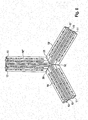
- FIG. 4 shows the profile according to the FIG. 3 in a cross section, wherein the pins 21, 22 of the corner connector 20 are illustrated. These are designed so that they are substantially adapted to the inner contour of the chambers 11, 12, and may be hollow parts, as shown, or massive parts. This results in a positive fit, which can be used for the positioning of the frame profiles 10 relative to the corner connector 20, wherein welded joints are mounted in the loading directions to allow the application as a heavy duty cabinet without a large number of seams to stabilize the corner joint is required.
- FIG. 5 shows, also in a cross-sectional view, a variant in which the pins 21 ', 22' of the connector 20 do not completely fill the interior of the chambers 11, 12, but nevertheless, due to their L-shaped configuration, on four sides within the respective chamber At this abutment and thus, in particular by the dovetail-shaped configuration of the contact webs 13 ', 13 ", are stably supported in the chambers 11, 12.
- An advantage of this embodiment is that a part 15, 17 of the perforations 15, 16, 17, 18th also in the region of the pins 21 ', 22' exposed, so that even in the region of the pins 21 ', 22' of the corner connector 20 fasteners (not shown) can be attached to which, for example mounting plates or mounting rails can be determined.
- FIG. 6 shows an example of a corner joint according to the present invention according to a second aspect, is omitted in the corner connector.
- the horizontal profiles 10 are cut so that they meet in the bottom region of the frame at an angle of 45 ° to each other, so that there is a 90 ° connection.
- the vertical profile 10 is cut to 45 °, so that in combination with the horizontal profiles 10, 10" results in the desired 90 ° connection.
- a mounting block 40 may be provided which includes a threaded opening 41, for example, for a pedestal or a crane eye.
- FIG. 7 shows the corner joint of FIG. 6 rotated by 180 ° and tilted, so to speak from the outside, as well as visually appealing arrangement.
- FIG. 9 shows the profiles according to FIG. 6 be cut in an advantageous manner.
- the 45 ° cuts 51, 52 extend only over the cross section of the chambers 11 or 12, so that the connecting web 13 remains intact and retains its torsional rigidity.
Landscapes
- Engineering & Computer Science (AREA)
- Microelectronics & Electronic Packaging (AREA)
- Power Engineering (AREA)
- Patch Boards (AREA)
- Cooling Or The Like Of Electrical Apparatus (AREA)
Applications Claiming Priority (1)
| Application Number | Priority Date | Filing Date | Title |
|---|---|---|---|
| DE201310110670 DE102013110670A1 (de) | 2013-09-26 | 2013-09-26 | Schaltschranksystem |
Publications (2)
| Publication Number | Publication Date |
|---|---|
| EP2854493A2 true EP2854493A2 (fr) | 2015-04-01 |
| EP2854493A3 EP2854493A3 (fr) | 2015-04-29 |
Family
ID=51609956
Family Applications (1)
| Application Number | Title | Priority Date | Filing Date |
|---|---|---|---|
| EP20140185900 Withdrawn EP2854493A3 (fr) | 2013-09-26 | 2014-09-23 | Système d'armoire électrique |
Country Status (3)
| Country | Link |
|---|---|
| EP (1) | EP2854493A3 (fr) |
| CN (1) | CN204464758U (fr) |
| DE (1) | DE102013110670A1 (fr) |
Cited By (1)
| Publication number | Priority date | Publication date | Assignee | Title |
|---|---|---|---|---|
| DE102020001435A1 (de) | 2020-03-04 | 2021-09-09 | Hydac Ag | Flüssigkeits-Luft-Kühlsystem |
Families Citing this family (2)
| Publication number | Priority date | Publication date | Assignee | Title |
|---|---|---|---|---|
| EP3716105A1 (fr) * | 2019-03-29 | 2020-09-30 | Rittal GmbH & Co. KG | Système de configuration de l'armoire de commande |
| CN117098353A (zh) * | 2023-07-31 | 2023-11-21 | 深圳市安卫普科技有限公司 | 通信设备 |
Citations (17)
| Publication number | Priority date | Publication date | Assignee | Title |
|---|---|---|---|---|
| DE4135108A1 (de) | 1991-10-24 | 1993-05-06 | Rittal-Werk Rudolf Loh Gmbh & Co Kg, 6348 Herborn, De | Rahmengestell fuer einen schaltschrank |
| DE19537015C1 (de) | 1995-10-04 | 1996-10-02 | Loh Kg Rittal Werk | Rahmengestell für einen Schaltschrank |
| DE19647790C2 (de) | 1996-11-19 | 2000-01-20 | Loh Kg Rittal Werk | Schaltschrank mit einem Rahmengestell |
| DE19536925C2 (de) | 1995-10-04 | 2000-04-20 | Loh Kg Rittal Werk | Rahmengestell für einen Schaltschrank |
| DE102006003770A1 (de) | 2006-01-25 | 2007-08-09 | Hager Electro Gmbh | Rahmengestell für einen Schalt- oder/und Verteilerschrank |
| DE102006036487B4 (de) | 2006-08-04 | 2009-04-16 | Era Elektrotechnik Ramsauer Gmbh Verteiler- Und Schaltschrankbau | Rahmenprofil |
| WO2012116673A1 (fr) | 2011-02-28 | 2012-09-07 | Rittal Gmbh & Co. Kg | Socle ou châssis de montage pour armoire électrique ou baie |
| WO2012116672A1 (fr) | 2011-02-28 | 2012-09-07 | Rittal Gmbh & Co. Kg | Châssis de montage pour armoire électrique ou baie |
| DE102011015859A1 (de) | 2011-04-01 | 2012-10-04 | Rittal Gmbh & Co. Kg | Selbsttragendes Kühlmodul |
| CN202617567U (zh) | 2012-04-01 | 2012-12-19 | 无锡豪润金属制品有限公司 | 转角连接件 |
| WO2013023633A2 (fr) | 2011-08-16 | 2013-02-21 | Rittal Gmbh & Co. Kg | Châssis de protection permettant de relier un climatiseur monté le toit d'une armoire électrique avec le toit de ladite armoire électrique |
| WO2013083421A1 (fr) | 2011-12-05 | 2013-06-13 | Schneider Electric Industries Sas | Armoire electrique a dissipation thermique amelioree |
| DE102012007081A1 (de) | 2012-04-11 | 2013-10-17 | Fresenius Medical Care Deutschland Gmbh | Verfahren und Vorrichtung zur langfristigen Überwachung der arteriellen Gefäßsteifigkeit und Gefäßkalzifikation eines Patienten |
| DE102012108108A1 (de) | 2012-08-31 | 2014-03-06 | Rittal Gmbh & Co. Kg | Schaltschrank mit einem Kühlgerät für die passive Schaltschrankkühlung |
| DE102012108110A1 (de) | 2012-08-31 | 2014-03-06 | Rittal Gmbh & Co. Kg | Kühlanordnung für in einem Innenraum eines Schaltschranks angeordnete Komponenten |
| DE102012108109A1 (de) | 2012-08-31 | 2014-03-06 | Rittal Gmbh & Co. Kg | Wärmetauscher für die Schaltschrankkühlung und eine entsprechende Kühlanordnung |
| DE102013101507A1 (de) | 2013-02-15 | 2014-08-21 | Rittal Gmbh & Co. Kg | Kombinierter Kabel- und Luftkanal für die Schaltschrankklimatisierung sowie ein entsprechender Schaltschrank |
Family Cites Families (6)
| Publication number | Priority date | Publication date | Assignee | Title |
|---|---|---|---|---|
| DE3939421C1 (fr) * | 1989-11-29 | 1990-10-25 | Eldon N.V., Drachten, Nl | |
| DE4227532C3 (de) * | 1992-08-20 | 1999-01-14 | Thielmann Ag Kg | Rahmenprofil für das Rahmengestell eines Schaltschrankes |
| DE19536950C1 (de) * | 1995-10-04 | 1996-11-21 | Loh Kg Rittal Werk | Rahmenschenkel für ein Rahmengestell eines Schaltschrankes |
| EP0948916B1 (fr) * | 1998-04-07 | 2004-06-30 | E.T.A. S.p.A. | Structure de support pour une armoire modulaire d'appareils électriques ou électroniques |
| US6965075B2 (en) * | 2001-03-01 | 2005-11-15 | Nitto Electric Works, Ltd. | Frame for electrical and electronic equipment housing cabinets and a frame joining structure |
| CN101577398B (zh) * | 2009-06-10 | 2012-05-02 | 深圳市怡富精密机械有限公司 | 一种便于装配的机柜框架及其装配方法 |
-
2013
- 2013-09-26 DE DE201310110670 patent/DE102013110670A1/de not_active Ceased
-
2014
- 2014-09-23 EP EP20140185900 patent/EP2854493A3/fr not_active Withdrawn
- 2014-09-26 CN CN201420775543.6U patent/CN204464758U/zh not_active Expired - Lifetime
Patent Citations (17)
| Publication number | Priority date | Publication date | Assignee | Title |
|---|---|---|---|---|
| DE4135108A1 (de) | 1991-10-24 | 1993-05-06 | Rittal-Werk Rudolf Loh Gmbh & Co Kg, 6348 Herborn, De | Rahmengestell fuer einen schaltschrank |
| DE19537015C1 (de) | 1995-10-04 | 1996-10-02 | Loh Kg Rittal Werk | Rahmengestell für einen Schaltschrank |
| DE19536925C2 (de) | 1995-10-04 | 2000-04-20 | Loh Kg Rittal Werk | Rahmengestell für einen Schaltschrank |
| DE19647790C2 (de) | 1996-11-19 | 2000-01-20 | Loh Kg Rittal Werk | Schaltschrank mit einem Rahmengestell |
| DE102006003770A1 (de) | 2006-01-25 | 2007-08-09 | Hager Electro Gmbh | Rahmengestell für einen Schalt- oder/und Verteilerschrank |
| DE102006036487B4 (de) | 2006-08-04 | 2009-04-16 | Era Elektrotechnik Ramsauer Gmbh Verteiler- Und Schaltschrankbau | Rahmenprofil |
| WO2012116673A1 (fr) | 2011-02-28 | 2012-09-07 | Rittal Gmbh & Co. Kg | Socle ou châssis de montage pour armoire électrique ou baie |
| WO2012116672A1 (fr) | 2011-02-28 | 2012-09-07 | Rittal Gmbh & Co. Kg | Châssis de montage pour armoire électrique ou baie |
| DE102011015859A1 (de) | 2011-04-01 | 2012-10-04 | Rittal Gmbh & Co. Kg | Selbsttragendes Kühlmodul |
| WO2013023633A2 (fr) | 2011-08-16 | 2013-02-21 | Rittal Gmbh & Co. Kg | Châssis de protection permettant de relier un climatiseur monté le toit d'une armoire électrique avec le toit de ladite armoire électrique |
| WO2013083421A1 (fr) | 2011-12-05 | 2013-06-13 | Schneider Electric Industries Sas | Armoire electrique a dissipation thermique amelioree |
| CN202617567U (zh) | 2012-04-01 | 2012-12-19 | 无锡豪润金属制品有限公司 | 转角连接件 |
| DE102012007081A1 (de) | 2012-04-11 | 2013-10-17 | Fresenius Medical Care Deutschland Gmbh | Verfahren und Vorrichtung zur langfristigen Überwachung der arteriellen Gefäßsteifigkeit und Gefäßkalzifikation eines Patienten |
| DE102012108108A1 (de) | 2012-08-31 | 2014-03-06 | Rittal Gmbh & Co. Kg | Schaltschrank mit einem Kühlgerät für die passive Schaltschrankkühlung |
| DE102012108110A1 (de) | 2012-08-31 | 2014-03-06 | Rittal Gmbh & Co. Kg | Kühlanordnung für in einem Innenraum eines Schaltschranks angeordnete Komponenten |
| DE102012108109A1 (de) | 2012-08-31 | 2014-03-06 | Rittal Gmbh & Co. Kg | Wärmetauscher für die Schaltschrankkühlung und eine entsprechende Kühlanordnung |
| DE102013101507A1 (de) | 2013-02-15 | 2014-08-21 | Rittal Gmbh & Co. Kg | Kombinierter Kabel- und Luftkanal für die Schaltschrankklimatisierung sowie ein entsprechender Schaltschrank |
Cited By (2)
| Publication number | Priority date | Publication date | Assignee | Title |
|---|---|---|---|---|
| DE102020001435A1 (de) | 2020-03-04 | 2021-09-09 | Hydac Ag | Flüssigkeits-Luft-Kühlsystem |
| DE102020001435B4 (de) * | 2020-03-04 | 2024-08-01 | Hydac Ag | Flüssigkeits-Luft-Kühlsystem |
Also Published As
| Publication number | Publication date |
|---|---|
| DE102013110670A1 (de) | 2015-03-26 |
| EP2854493A3 (fr) | 2015-04-29 |
| CN204464758U (zh) | 2015-07-08 |
Similar Documents
| Publication | Publication Date | Title |
|---|---|---|
| EP1967938B1 (fr) | Armoire électrique destinée à la réception de modules enfichables électroniques dotée d'un échangeur thermique | |
| EP1719044B1 (fr) | Ensemble de dispositifs | |
| EP2909901B1 (fr) | Boîtier antidéflagrant équipé d'un ventilateur | |
| EP3311083B1 (fr) | Vitrine réfrigérée | |
| EP3281506B1 (fr) | Ensemble d'armoires électriques avec une rangée d'armoires électriques et un appareil de refroidissement intégré dans la rangée | |
| EP1667862B1 (fr) | Installation de climatisation montee sur le toit d'un vehicule, notamment d'un omnibus | |
| AT399075B (de) | Rückwand für ein gehäuse zur aufnahme elektrischer baugruppen | |
| WO2018036764A1 (fr) | Dispositif de refroidissement conçu pour un ensemble batterie et unité constituée d'un ensemble batterie et d'un dispositif de refroidissement | |
| EP2887839A1 (fr) | Appareil de réfrigération | |
| DE20200484U1 (de) | Kühlvorrichtung für Bauteile, insbesondere für elektrische oder elektronische Bauteile, wie Stromrichter o.dgl. | |
| EP2199706A1 (fr) | Appareil de climatisation | |
| EP0900621A2 (fr) | Module d'alimentation électrique | |
| WO2020058279A1 (fr) | Installation de climatisation sur toit modulaire | |
| DE112019007040T5 (de) | Wärmepumpenkreislauf-Vorrichtung und Wärmepumpen-Wassererhitzer | |
| DE102013110670A1 (de) | Schaltschranksystem | |
| DE102013113222A1 (de) | Schaltschrank mit einer kühlenden verbindungsplatte zur verbindung mehrerer stromsammelschienen | |
| DE202014100662U1 (de) | Kühlregal | |
| DE202009019071U1 (de) | Verdampfer und Kühleinrichtung unter Verwendung derartiger Verdampfer | |
| DE202011110056U1 (de) | Klimaschrank | |
| EP3447416B1 (fr) | Appareil de réfrigération et/ou de congélation et son procédé de fabrication | |
| DE19825602A1 (de) | Schaltschranksystem | |
| DE3507255A1 (de) | Gehaeuse fuer elektrische bauteile | |
| DE102021002168B4 (de) | Klimatisierungs-Dachmodul | |
| DE202012006447U1 (de) | Vorrichtung zur Spannungsversorgung eines Kraftfahrzeugs mit einem Kühlerblock | |
| WO2024046911A1 (fr) | Batterie de traction à régulation de température de fluide |
Legal Events
| Date | Code | Title | Description |
|---|---|---|---|
| PUAL | Search report despatched |
Free format text: ORIGINAL CODE: 0009013 |
|
| PUAI | Public reference made under article 153(3) epc to a published international application that has entered the european phase |
Free format text: ORIGINAL CODE: 0009012 |
|
| 17P | Request for examination filed |
Effective date: 20140923 |
|
| AK | Designated contracting states |
Kind code of ref document: A2 Designated state(s): AL AT BE BG CH CY CZ DE DK EE ES FI FR GB GR HR HU IE IS IT LI LT LU LV MC MK MT NL NO PL PT RO RS SE SI SK SM TR |
|
| AX | Request for extension of the european patent |
Extension state: BA ME |
|
| AK | Designated contracting states |
Kind code of ref document: A3 Designated state(s): AL AT BE BG CH CY CZ DE DK EE ES FI FR GB GR HR HU IE IS IT LI LT LU LV MC MK MT NL NO PL PT RO RS SE SI SK SM TR |
|
| AX | Request for extension of the european patent |
Extension state: BA ME |
|
| RIC1 | Information provided on ipc code assigned before grant |
Ipc: H02B 1/01 20060101ALI20150325BHEP Ipc: A47B 47/03 20060101ALI20150325BHEP Ipc: H05K 7/18 20060101AFI20150325BHEP |
|
| R17P | Request for examination filed (corrected) |
Effective date: 20151026 |
|
| RBV | Designated contracting states (corrected) |
Designated state(s): AL AT BE BG CH CY CZ DE DK EE ES FI FR GB GR HR HU IE IS IT LI LT LU LV MC MK MT NL NO PL PT RO RS SE SI SK SM TR |
|
| 17Q | First examination report despatched |
Effective date: 20200304 |
|
| STAA | Information on the status of an ep patent application or granted ep patent |
Free format text: STATUS: THE APPLICATION IS DEEMED TO BE WITHDRAWN |
|
| 18D | Application deemed to be withdrawn |
Effective date: 20200715 |