EP2854638B1 - Sensorpatrone - Google Patents
Sensorpatrone Download PDFInfo
- Publication number
- EP2854638B1 EP2854638B1 EP13723795.4A EP13723795A EP2854638B1 EP 2854638 B1 EP2854638 B1 EP 2854638B1 EP 13723795 A EP13723795 A EP 13723795A EP 2854638 B1 EP2854638 B1 EP 2854638B1
- Authority
- EP
- European Patent Office
- Prior art keywords
- sensor
- needle
- operable
- insertion mechanism
- subject
- Prior art date
- Legal status (The legal status is an assumption and is not a legal conclusion. Google has not performed a legal analysis and makes no representation as to the accuracy of the status listed.)
- Active
Links
Images




Classifications
-
- A—HUMAN NECESSITIES
- A61—MEDICAL OR VETERINARY SCIENCE; HYGIENE
- A61B—DIAGNOSIS; SURGERY; IDENTIFICATION
- A61B5/00—Measuring for diagnostic purposes; Identification of persons
- A61B5/68—Arrangements of detecting, measuring or recording means, e.g. sensors, in relation to patient
- A61B5/6846—Arrangements of detecting, measuring or recording means, e.g. sensors, in relation to patient specially adapted to be brought in contact with an internal body part, i.e. invasive
- A61B5/6847—Arrangements of detecting, measuring or recording means, e.g. sensors, in relation to patient specially adapted to be brought in contact with an internal body part, i.e. invasive mounted on an invasive device
- A61B5/6848—Needles
- A61B5/6849—Needles in combination with a needle set
-
- A—HUMAN NECESSITIES
- A61—MEDICAL OR VETERINARY SCIENCE; HYGIENE
- A61B—DIAGNOSIS; SURGERY; IDENTIFICATION
- A61B17/00—Surgical instruments, devices or methods
- A61B17/34—Trocars; Puncturing needles
- A61B17/3468—Trocars; Puncturing needles for implanting or removing devices, e.g. prostheses, implants, seeds, wires
-
- A—HUMAN NECESSITIES
- A61—MEDICAL OR VETERINARY SCIENCE; HYGIENE
- A61B—DIAGNOSIS; SURGERY; IDENTIFICATION
- A61B5/00—Measuring for diagnostic purposes; Identification of persons
- A61B5/145—Measuring characteristics of blood in vivo, e.g. gas concentration or pH-value ; Measuring characteristics of body fluids or tissues, e.g. interstitial fluid or cerebral tissue
- A61B5/14532—Measuring characteristics of blood in vivo, e.g. gas concentration or pH-value ; Measuring characteristics of body fluids or tissues, e.g. interstitial fluid or cerebral tissue for measuring glucose, e.g. by tissue impedance measurement
-
- A—HUMAN NECESSITIES
- A61—MEDICAL OR VETERINARY SCIENCE; HYGIENE
- A61B—DIAGNOSIS; SURGERY; IDENTIFICATION
- A61B5/00—Measuring for diagnostic purposes; Identification of persons
- A61B5/145—Measuring characteristics of blood in vivo, e.g. gas concentration or pH-value ; Measuring characteristics of body fluids or tissues, e.g. interstitial fluid or cerebral tissue
- A61B5/14542—Measuring characteristics of blood in vivo, e.g. gas concentration or pH-value ; Measuring characteristics of body fluids or tissues, e.g. interstitial fluid or cerebral tissue for measuring blood gases
-
- A—HUMAN NECESSITIES
- A61—MEDICAL OR VETERINARY SCIENCE; HYGIENE
- A61B—DIAGNOSIS; SURGERY; IDENTIFICATION
- A61B5/00—Measuring for diagnostic purposes; Identification of persons
- A61B5/145—Measuring characteristics of blood in vivo, e.g. gas concentration or pH-value ; Measuring characteristics of body fluids or tissues, e.g. interstitial fluid or cerebral tissue
- A61B5/14546—Measuring characteristics of blood in vivo, e.g. gas concentration or pH-value ; Measuring characteristics of body fluids or tissues, e.g. interstitial fluid or cerebral tissue for measuring analytes not otherwise provided for, e.g. ions, cytochromes
-
- A—HUMAN NECESSITIES
- A61—MEDICAL OR VETERINARY SCIENCE; HYGIENE
- A61B—DIAGNOSIS; SURGERY; IDENTIFICATION
- A61B5/00—Measuring for diagnostic purposes; Identification of persons
- A61B5/145—Measuring characteristics of blood in vivo, e.g. gas concentration or pH-value ; Measuring characteristics of body fluids or tissues, e.g. interstitial fluid or cerebral tissue
- A61B5/1468—Measuring characteristics of blood in vivo, e.g. gas concentration or pH-value ; Measuring characteristics of body fluids or tissues, e.g. interstitial fluid or cerebral tissue using chemical or electrochemical methods, e.g. by polarographic means
- A61B5/1473—Measuring characteristics of blood in vivo, e.g. gas concentration or pH-value ; Measuring characteristics of body fluids or tissues, e.g. interstitial fluid or cerebral tissue using chemical or electrochemical methods, e.g. by polarographic means invasive, e.g. introduced into the body by a catheter
-
- A—HUMAN NECESSITIES
- A61—MEDICAL OR VETERINARY SCIENCE; HYGIENE
- A61B—DIAGNOSIS; SURGERY; IDENTIFICATION
- A61B5/00—Measuring for diagnostic purposes; Identification of persons
- A61B5/145—Measuring characteristics of blood in vivo, e.g. gas concentration or pH-value ; Measuring characteristics of body fluids or tissues, e.g. interstitial fluid or cerebral tissue
- A61B5/1468—Measuring characteristics of blood in vivo, e.g. gas concentration or pH-value ; Measuring characteristics of body fluids or tissues, e.g. interstitial fluid or cerebral tissue using chemical or electrochemical methods, e.g. by polarographic means
- A61B5/1486—Measuring characteristics of blood in vivo, e.g. gas concentration or pH-value ; Measuring characteristics of body fluids or tissues, e.g. interstitial fluid or cerebral tissue using chemical or electrochemical methods, e.g. by polarographic means using enzyme electrodes, e.g. with immobilised oxidase
- A61B5/14865—Measuring characteristics of blood in vivo, e.g. gas concentration or pH-value ; Measuring characteristics of body fluids or tissues, e.g. interstitial fluid or cerebral tissue using chemical or electrochemical methods, e.g. by polarographic means using enzyme electrodes, e.g. with immobilised oxidase invasive, e.g. introduced into the body by a catheter or needle or using implanted sensors
-
- A—HUMAN NECESSITIES
- A61—MEDICAL OR VETERINARY SCIENCE; HYGIENE
- A61B—DIAGNOSIS; SURGERY; IDENTIFICATION
- A61B5/00—Measuring for diagnostic purposes; Identification of persons
- A61B5/68—Arrangements of detecting, measuring or recording means, e.g. sensors, in relation to patient
- A61B5/6846—Arrangements of detecting, measuring or recording means, e.g. sensors, in relation to patient specially adapted to be brought in contact with an internal body part, i.e. invasive
- A61B5/6847—Arrangements of detecting, measuring or recording means, e.g. sensors, in relation to patient specially adapted to be brought in contact with an internal body part, i.e. invasive mounted on an invasive device
- A61B5/686—Permanently implanted devices, e.g. pacemakers, other stimulators, biochips
-
- A—HUMAN NECESSITIES
- A61—MEDICAL OR VETERINARY SCIENCE; HYGIENE
- A61B—DIAGNOSIS; SURGERY; IDENTIFICATION
- A61B5/00—Measuring for diagnostic purposes; Identification of persons
- A61B5/14—Devices for taking samples of blood ; Measuring characteristics of blood in vivo, e.g. gas concentration within the blood, pH-value of blood
- A61B5/1405—Devices for taking blood samples
- A61B5/1411—Devices for taking blood samples by percutaneous method, e.g. by lancet
-
- A—HUMAN NECESSITIES
- A61—MEDICAL OR VETERINARY SCIENCE; HYGIENE
- A61B—DIAGNOSIS; SURGERY; IDENTIFICATION
- A61B5/00—Measuring for diagnostic purposes; Identification of persons
- A61B5/15—Devices for taking samples of blood
- A61B5/150007—Details
- A61B5/150015—Source of blood
- A61B5/15003—Source of blood for venous or arterial blood
-
- A—HUMAN NECESSITIES
- A61—MEDICAL OR VETERINARY SCIENCE; HYGIENE
- A61B—DIAGNOSIS; SURGERY; IDENTIFICATION
- A61B5/00—Measuring for diagnostic purposes; Identification of persons
- A61B5/15—Devices for taking samples of blood
- A61B5/150007—Details
- A61B5/150053—Details for enhanced collection of blood or interstitial fluid at the sample site, e.g. by applying compression, heat, vibration, ultrasound, suction or vacuum to tissue; for reduction of pain or discomfort; Skin piercing elements, e.g. blades, needles, lancets or canulas, with adjustable piercing speed
- A61B5/150106—Means for reducing pain or discomfort applied before puncturing; desensitising the skin at the location where body is to be pierced
- A61B5/15016—Means for reducing pain or discomfort applied before puncturing; desensitising the skin at the location where body is to be pierced by accessories for bringing the piercing element into the body, e.g. through rotation of the piercing element
-
- A—HUMAN NECESSITIES
- A61—MEDICAL OR VETERINARY SCIENCE; HYGIENE
- A61B—DIAGNOSIS; SURGERY; IDENTIFICATION
- A61B5/00—Measuring for diagnostic purposes; Identification of persons
- A61B5/15—Devices for taking samples of blood
- A61B5/150007—Details
- A61B5/150206—Construction or design features not otherwise provided for; manufacturing or production; packages; sterilisation of piercing element, piercing device or sampling device
- A61B5/150221—Valves
-
- A—HUMAN NECESSITIES
- A61—MEDICAL OR VETERINARY SCIENCE; HYGIENE
- A61B—DIAGNOSIS; SURGERY; IDENTIFICATION
- A61B5/00—Measuring for diagnostic purposes; Identification of persons
- A61B5/15—Devices for taking samples of blood
- A61B5/150007—Details
- A61B5/150206—Construction or design features not otherwise provided for; manufacturing or production; packages; sterilisation of piercing element, piercing device or sampling device
- A61B5/150305—Packages specially adapted for piercing devices or blood sampling devices
-
- A—HUMAN NECESSITIES
- A61—MEDICAL OR VETERINARY SCIENCE; HYGIENE
- A61B—DIAGNOSIS; SURGERY; IDENTIFICATION
- A61B5/00—Measuring for diagnostic purposes; Identification of persons
- A61B5/15—Devices for taking samples of blood
- A61B5/150007—Details
- A61B5/150374—Details of piercing elements or protective means for preventing accidental injuries by such piercing elements
- A61B5/150534—Design of protective means for piercing elements for preventing accidental needle sticks, e.g. shields, caps, protectors, axially extensible sleeves, pivotable protective sleeves
- A61B5/150633—Protective sleeves which are axially extensible, e.g. sleeves connected to, or integrated in, the piercing or driving device; pivotable protective sleeves
-
- A—HUMAN NECESSITIES
- A61—MEDICAL OR VETERINARY SCIENCE; HYGIENE
- A61B—DIAGNOSIS; SURGERY; IDENTIFICATION
- A61B5/00—Measuring for diagnostic purposes; Identification of persons
- A61B5/15—Devices for taking samples of blood
- A61B5/150992—Blood sampling from a fluid line external to a patient, such as a catheter line, combined with an infusion line; Blood sampling from indwelling needle sets, e.g. sealable ports, luer couplings or valves
-
- A—HUMAN NECESSITIES
- A61—MEDICAL OR VETERINARY SCIENCE; HYGIENE
- A61B—DIAGNOSIS; SURGERY; IDENTIFICATION
- A61B5/00—Measuring for diagnostic purposes; Identification of persons
- A61B5/15—Devices for taking samples of blood
- A61B5/151—Devices specially adapted for taking samples of capillary blood, e.g. by lancets, needles or blades
- A61B5/15142—Devices intended for single use, i.e. disposable
-
- A—HUMAN NECESSITIES
- A61—MEDICAL OR VETERINARY SCIENCE; HYGIENE
- A61M—DEVICES FOR INTRODUCING MEDIA INTO, OR ONTO, THE BODY; DEVICES FOR TRANSDUCING BODY MEDIA OR FOR TAKING MEDIA FROM THE BODY; DEVICES FOR PRODUCING OR ENDING SLEEP OR STUPOR
- A61M5/00—Devices for bringing media into the body in a subcutaneous, intra-vascular or intramuscular way; Accessories therefor, e.g. filling or cleaning devices, arm rests
- A61M5/14—Infusion devices, e.g. infusing by gravity; Blood infusion; Accessories therefor
- A61M5/158—Needles for infusions; Accessories therefor, e.g. for inserting infusion needles, or for holding them on the body
- A61M2005/1585—Needle inserters
Definitions
- the invention relates to sensors for in vivo monitoring of an analyte, in particular to devices for inserting a sensor into a subject.
- analyte levels in his or her blood stream.
- the subject routinely monitors the glucose levels to avoid hypoglycemic episodes and hyperglycemic episodes.
- other analytes such as lactate or oxygen, may be measured.
- a typical means of performing such monitoring is the repeated drawing of blood by the subject to provide a sample for analysis by a monitoring system. This provides a cost effective way monitoring chronic diseases such as diabetes, but it may be inconvenient and only provides data on the analyte concentration at the time intervals when the test was performed.
- an electrochemical sensor may be inserted into a subcutaneous region of the subject where the analyte concentration is continuously monitored and/or logged.
- United States patent application US 2008/0242962 A1 discloses a monitoring system for monitoring analyte concentration, such as glucose, with an implantable sensor.
- a disadvantage of current systems for inserting subcutaneous sensor systems is that the they may require that an inserter is used each time a sensor is inserted into a subject.
- a further disadvantage of current systems is that typically a large volume and amount of packaging is used.
- the invention is a sensor cartridge with an insertion mechanism as defined in the independent claim.
- United States patent application US 2006/0142651 A1 which represents the closest prior art, discloses a sensor cartridge with an insertion mechanism which is not operable for moving a sensor connector from an initial position to a mounted position where it is locked and left when withdrawing an insertion needle.
- the present disclosure provides for a sensor cartridge comprising a sterile capsule.
- the sensor cartridge further comprises a sensor within the sterile capsule.
- the sensor is located at an initial position within the sterile capsule.
- the sensor cartridge further comprises an insertion needle for inserting the sensor into a subject.
- the insertion needle is within the sterile capsule.
- the insertion needle may be a hollow needle with a cross-section that has been removed.
- the needle may have a cross-section that resembles the letter "c.”
- the sensor cartridge further comprises a sensor mounting unit for receiving the sensor at a mounted position.
- the sensor mounting unit comprises an adhesive surface for attaching to an exterior surface of the subject.
- the sensor cartridge further comprises an insertion mechanism operable for actuating the insertion needle and moving the sensor from the initial position to the mounted position.
- This embodiment may be advantageous because the sensor, insertion needle and sensor mounting unit can all be incorporated into one package which may be provided with a sterile capsule.
- a subject or healthcare provider installing a sensor into a subject may simply adhere the sensor mounting unit to the exterior surface of the subject and then use the insertion mechanism to insert the sensor into the subject. The insertion needle moves the sensor into the subject and into the mounted position, the insertion needle then withdraws.
- the insertion needle is protected by what was previously the sterile capsule. This may eliminate the need for individual sharps disposal units.
- the insertion needle may be a hollow needle with a channel cut through it or a solid needle with a channel cut through it for accommodating the sensor.
- a cross-section of the needle has a C-shape to it.
- the invention provides for a sensor cartridge comprising a sterile capsule.
- the sensor cartridge further comprises a sensor within the sterile capsule.
- the sensor cartridge further comprises a sensor connector connected to the sensor in an initial position.
- the sensor cartridge further comprises an insertion needle for inserting the sensor into a subject.
- the insertion needle is within the sterile capsule.
- the insertion needle may be a hollow needle with a cross-section that has been removed. For example, the needle may have a cross-section that resembles the letter "c.”
- the sensor may be attached to or located within the insertion needle.
- the sensor cartridge further comprises a sensor mounting unit for receiving the sensor connector at a mounted position.
- the sensor mounting unit comprises an adhesive surface for attaching to an exterior surface of the subject.
- the sensor cartridge further comprises an insertion mechanism operable for actuating the insertion needle and moving the sensor connector from the initial position to the mounted position.
- This embodiment may be advantageous because the sensor, insertion needle and sensor mounting unit can all be incorporated into one package which may be provided with a sterile capsule.
- a subject or healthcare provider installing a sensor into a subject may simply adhere the sensor mounting unit to the exterior surface of the subject and then use the insertion mechanism to insert the sensor into the subject.
- the insertion needle moves the sensor into the subject and the sensor connector into the mounted position, the insertion needle then withdraws.
- the insertion needle is protected by what was previously the sterile capsule. This may eliminate the need for individual sharps disposal units.
- the insertion needle may be a hollow needle with a channel cut through it or a solid needle with a channel cut through it for accommodating the sensor.
- a cross-section of the needle has a C-shape to it.
- the sensor cartridge further comprises a knob.
- the insertion mechanism is operable for actuating the insertion needle in a linear direction upon rotation of the knob.
- This embodiment may be beneficial because the knob forms a so called helper mechanism which is used for actuating the insertion mechanism. If a subject were to use the sensor cartridge for installing a sensor into his or herself it may be difficult for the subject to directly push the needle into his or herself.
- the rotation of the knob causes the insertion mechanism to linearly insert the insertion needle. However, because the knob is rotated in a different direction in a rotational fashion it is easier for the subject to perform the act. In some embodiments, the knob is rotated in only one direction. The rotation motion first inserts the needle and then withdraws it. In other embodiments the subject turns the needle in one direction to insert the needle. After insertion, the subject turns the knob in the opposite direction to withdraw the needle.
- the sensor cartridge further comprises a bellows for providing the sterile capsule.
- the insertion mechanism comprises the bellows.
- the bellows are operable for being compressed by an operator or a subject.
- the insertion mechanism is operable for actuating the insertion needle upon compression of the bellows.
- the insertion mechanism may be operated by compressing or depressing the bellows. This embodiment may be beneficial because it provides a very simple mechanism which also provides the sterile capsule. Due to the lack of a further moving part it may reduce the cost of manufacturing using such a sensor cartridge.
- the bellows may also remove the insertion needle from the subject. When the bellows are no longer compressed they may spring back to their original form and withdraw the insertion needle in the process.
- the sensor mounting unit is detachable from the insertion mechanism.
- the sensor mounting unit may be attached to the insertion mechanism and able to be removed from the insertion mechanism.
- the insertion mechanism is operable for detaching the sensor mounting unit from the insertion mechanism at a predetermined point in the actuation of the insertion needle. This embodiment may be beneficial because it allows the insertion mechanism to be removed from the sensor mounting unit. This may reduce the weight that the subject needs to carry when a sensor is installed into the subject.
- the insertion mechanism comprises a spring clip for attaching the sensor mounting unit to the insertion mechanism.
- the insertion mechanism may be operable for detaching the spring clip from the insertion mechanism or detaching the sensor mounting unit from the insertion mechanism.
- the insertion mechanism is able for opening the spring clip to detach the sensor mounting unit from the insertion mechanism.
- the sensor cartridge further comprises a pressurized vessel for forming the sterile capsule.
- a pressure differential between the pressurized vessel and outside the sensor cartridge is operable for attaching the insertion mechanism to the mounting unit.
- the sensor cartridge further comprises a seal for maintaining the pressure differential.
- the insertion mechanism is operable for causing the seal and/or a valve to release the pressure differential during actuation of the insertion mechanism.
- This embodiment may be beneficial because the insertion mechanism is automatically detached from the sensor mounting unit when the pressure is released and also because the sterile capsule was formed by the pressurized vessel. When the pressurized vessel loses its pressure the sterile capsule may decrease in size. This reduces the amount of waste that needs to be disposed of.
- the insertion mechanism may cause or be operable to release the pressure differential at a predetermined point in the actuation of the insertion needle. This causes the insertion mechanism to detach from the sensor mounting unit.
- the sterile capsule is a hollow cavity.
- the insertion mechanism comprises a piston.
- the insertion mechanism is operable for pushing the piston into the hollow cavity for actuating the insertion mechanism for driving the insertion needle into the subject.
- the sterile capsule is sealed with a septum.
- the insertion mechanism is operable for pushing the insertion needle through the septum.
- the septum is operable for attaching to the sensor mounting unit.
- the use of a septum is advantageous because the needle can cross through the septum breaking out of the sterile capsule.
- the use of a septum may eliminate the need for removing a seal or sealing means from a sterile capsule.
- the sensor cartridge further comprises a cover for covering the adhesive surface and for sealing the sterile compartment.
- a portion of the insertion mechanism could be restrained by the cover or a portion of a linkage may not be able to move freely until the cover is removed.
- This embodiment may be advantageous because the removal of the cover of the adhesive surface enables the insertion needle to insert the sensor into the subject. and functions as a safety.
- removal of the cover enables actuation of the insertion mechanism.
- This embodiment is advantageous because it may reduce or eliminate the actuation of the insertion mechanism when the sensor mounting unit is not attached to the exterior surface of a subject. This may for instance reduce the chances that the insertion mechanism will be actuated at the wrong time and inflict an injury on someone with the insertion needle.
- the sensor cartridge further comprises a package for forming the sterile capsule.
- the cover forms at least a portion of the package. This embodiment may be advantageous because the cover forms part of the packaging of the sensor cartridge and the packaging forms the sterile capsule. This may reduce the amount of waste which needs to be discarded and may also reduce the manufacturing costs of the sensor cartridge.
- the insertion mechanism comprises a safety which is operable for being moved from an operable to an inoperable position.
- the insertion mechanism prevents actuation of the needle when the safety is in the inoperable position and the mechanism is operable to actuate the needle when the safety is in the operable position.
- This embodiment may be advantageous because it may prevent actuation of the insertion mechanism when it is not intended. This may for instance reduce the chance of accidental injury by the insertion needle.
- the insertion mechanism is operable to couple to a helper mechanism of an inserter.
- the helper mechanism is operable for actuating the insertion mechanism.
- the use of a helper mechanism may be beneficial because the helper mechanism may take work or action directed in a direction other than the direction that the insertion needle travels. This may make it easier for a subject to actuate the insertion mechanism his or herself.
- the senor is an electrochemical sensor.
- the senor is any one of the following: a glucose sensor, a lactate sensor, and an oxygen sensor.
- the insertion mechanism is further operable for retracting the insertion needle into the sterile capsule after actuating the insertion needle and moving the sensor from the initial position to the mounted position.
- This embodiment may be beneficial because the sterile capsule may provide protection to the used insertion needle. This may for instance reduce the need for a separate sharps container.
- an inserter comprises a helper mechanism operable for coupling to an insertion mechanism of a sensor cartridge according to an embodiment of the invention.
- the inserter may be a re-usable inserter able to be reloaded only with a new sensor cartridge or cartridges after use. This may enable the use of a reusable inserter for inserting single use sensors.
- the helper mechanism may prevent a used sensor cartridge from being used a second time.
- the inserter is operable for puncturing a package of the sensor cartridge for forming the sterile capsule to couple to the insertion mechanism. This may be beneficial because puncturing of the package by the helper mechanism may do work that is necessary to prepare the sensor cartridge for use.
- the present disclosure provides for an inserter assembly comprising an inserter according to an embodiment of the invention and a sensor cartridge according to an embodiment of the invention.
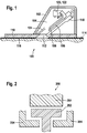
- Fig. 1 shows an example of a sensor cartridge according to the invention.
- a package 102 which forms a sterile capsule 104.
- an insertion needle 106 Within the sterile capsule 104 is an insertion needle 106.
- a sensor 108 which is located within a cavity of the insertion needle 106.
- There is a sensor mounting unit 110 which forms a bottom portion of the sterile capsule 104.
- the sensor mounting unit 110 has a hole 112 through which the insertion needle 106 can be inserted into a subject 114.
- the sensor mounting unit 110 has an adhesive surface 116 in contact with the subject 114 for attaching the sensor mounting unit 110 to the subject 114.
- an insertion mechanism 118 for actuating the insertion needle 106.
- the sensor connector 120 is mounted near the top of the insertion needle 106.
- the sensor connector 120 is connected to the sensor 108.
- the sensor connector 120 is moved from an initial position 122 to a mounted position 124.
- the sensor connector 120 may lock into the mounted position 124.
- the insertion needle 106 then withdraws leaving the sensor 108 within the subject 114 and the sensor connector 120 in the mounted position 124.
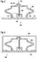
- Fig. 2 shows a cross-sectional view of a mechanical coupling 200 between the insertion mechanism 202 and a helper mechanism 204.
- the insertion mechanism 202 forms a T-shaped cross section which can be snapped into the portion of the helper mechanism 204. This T-like section allows the helper mechanism 204 to both push and pull the insertion mechanism 202 to actuate it.
- Fig. 3 shows an inserter assembly 300.
- the inserter assembly 300 comprises an inserter 302 and a sensor mounting unit 304.
- the sensor mounting unit 304 comprises the sterile capsule and can be removed from the inserter 302. When the insertion needle is used the sensor mounting unit 304 is released from the inserter 302. Additionally, in some examples the insertion mechanism may cause the insertion needle to withdraw back into the sterile capsule after insertions. This may have the advantage that the formerly sterile capsule provides protection to the used insertion needle.
- Fig. 4 shows a further example of a sensor cartridge 400 according to the invention.
- the example shown in Fig. 4 is similar to that shown in Fig. 1 with several structural differences.
- this example there is a cover 402 covering the adhesive surface and the hole 112. Additionally this sensor cartridge 400 is intended to be operated manually and not by a helper mechanism or actuating mechanism of some sort.
- the insertion mechanism 118 comprises a guide 406 or slide, which is used to control the orientation and of the insertion needle 106. During use the subject would take the cover 402 off and adhere the sensor mounting unit 110 to another surface such as the stomach.
- the subject would then press on the package 102 depressing the area of the pushing surface 404. This would cause the insertion needle 106 to be guided by the guide 406 and enter the subject. When the subject stops pressing on the pushing surface 404 the insertion needle 406 would retract leaving the sensor connector 120 in the mounted position 124 and the sensor 108 within the subject. In some examples the 102 and the insertion mechanism 118 would then detach from the sensor mounting unit 110.
- Fig. 5 shows an example of a sensor cartridge according to the invention.
- the sensor cartridge 500 comprises a bellows 502.
- the bellows are attached to a sensor mounting unit 110.
- the bellows 502 and the sensor mounting unit 110 form a sterile capsule 104.
- Within the sterile capsule 104 is an insertion needle 106 for inserting a sensor 108.
- the sensor 108 is connected to a sensor mounting unit 110 which is located in an initial position 122.
- the bellows is able to collapse and the insertion needle 106 is driven into the subject which causes the sensor 108 to be located within the subject and the sensor connector 120 is moved into the mounted position 124.
- the insertion needle 106 When the force 504 is released the insertion needle 106 is retracted by the spring-like effect of the bellows 502. In some mechanisms this causes the bellows 502 to automatically detach from the sensor mounting unit 110. In other examples a connector or screw connection may be used to remove the bellows 502 from the sensor mounting unit 110.
- Fig. 6 illustrates a safety 600 which may be implemented on the sensor cartridge 500 shown in Fig. 5 .
- a large wire or bar is positioned between the top of the bellows 502 and the sensor mounting unit 110. In this case it is not possible to depress the bellows.
- Fig. 7 shows the same safety 600 in an enabled position.
- the safety 600 has been rotated 700.
- the safety 600 no longer prevents the bellows 502 from being depressed.
- a force may be applied along direction 504 in order to insert the sensor into the subject.
- Fig. 8 shows a sensor cartridge 800 according to a further example of the invention.
- a sensor mounting unit 110 Above this there is a package 102 with a flexible surface or at least partially flexible that is pressurized. This forms a sterile capsule 104 and essentially is a pressurized vessel 802.
- a valve 808 is used to release pressure when a force in the direction of 810 is applied to the sensor cartridge 800.
- a force in the direction 810 causes the pressurized vessel 802 to gradually lose pressure as the sensor cartridge 800 is depressed.
- Insertion needle 106 goes through the hole 112. In some examples there may be a septum present to maintain the pressure of the pressurized vessel 802.
- the spring 806 will return the insertion needle 106 to its original starting position after the force in the direction 810 is released. After the insertion needle 106 has been inserted the pressure in the pressurized vessel 802 is lower and the seal 804 may no longer function. This may cause the entire package 102 to release from the base plate 110.
- Fig. 9 shows a further example of a sensor cartridge 900.
- Fig. 9 Only a portion of the example in Fig. 9 is shown.
- the example shown in Fig. 9 is equivalent to that shown in Fig. 8 except a pressurized vessel is not used to maintain a contact between the package 102 and the base plate 110.
- a spring retainer ring 902 which holds the package 102 to the base plate 110. When the insertion needle is retracted the spring 902 is released and the package or cover 102 is freely removed from the base plate 110.
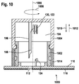
- Fig. 10 shows an example of a sensor cartridge 1000 according to an example.
- a cylindrical gear 1002 and a knob 1004 form the sterile capsule 104.
- the knob 1004 is operable for driving along the cylindrical gear 1002.
- the gear 1002 is shaped such that as the knob is continually rotated in direction 1006 the insertion needle 106 reaches its apex of insertion and then begins to go back in the retraction direction 1012.
- the subject rotates the knob 1004 as far as possible and then after reaching a stopping point the subject rotates the knob in the direction opposite to 1006 to go back in the direction 1012.
- the gear 1002 is attached to the sensor mounting unit 110. Also shown is an optional protector 1014 which protects the surface or grooves of the cylindrical gear 1002. If the protector 1014 is not present in some examples, in other examples the protector 1014 is collapsible or crushable. In other examples the protector 1014 falls or is torn off as the knob 1004 is turned.
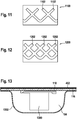
- Fig. 11 shows a gear pattern 1100 which may be used for the cylindrical gear 1002.
- the example 1100 is a gear with two slots 1102.
- the gear pattern 1100 is wrapped around a cylinder.
- Guides which control the depth of the insertion needle may be positioned in each of the slots. As the cylinder is rotated or as the guides are rotated relative to the cylinder the guides follow the slots. This causes the insertion needle to first travel into the subject and then to be retracted from the subject. With a single rotational motion, the insertion needle is inserted and retracted.
- Fig. 12 shows a different gear pattern with three slots 1103 instead of two as was shown in Fig. 11 .
- the gear pattern 1200 is wrapped around a cylinder.
- Guides which control the depth of the insertion needle may be positioned in each of the slots. As the cylinder is rotated or as the guides are rotated relative to the cylinder the guides follow the slots. This causes the insertion needle to first travel into the subject and then to be retracted from the subject. With a single rotational motion, the insertion needle is inserted and retracted.
- Fig. 13 shows a sensor cartridge 1300 according to an example.
- the blister packaging 1302 or retail packaging forms the sterile capsule 104 with the sensor mounting unit 110.
- the sensor cartridge 1300 is removed from the packaging 1302 by removing the cover 402 and placing the adhesive surface 116 on the surface of the subject.
- This example may have the advantage that reduces the amount of waste which is produced and may also reduce the manufacturing cost as the packaging of the product is incorporated into forming the sterile capsule 104.
- Fig. 14 shows an example similar as shown in Fig. 13 .
- a sensor cartridge 1400 covered by a blister packaging 1402 which is again sealed by a cover 402 in the same fashion as shown in Fig. 13 except in this case the sterile capsule 104 is just bigger than the sensor cartridge 1400.
- This example may have several advantages, first the surface surrounding the sensor cartridge 1400 may be easier for a subject to grab. Additionally, the cartridge can be inserted into a system which punctures the packaging 1402 and enables it to actuate the insertion mechanism within the sensor cartridge 1400.
- Fig. 15 shows a sensor cartridge 1500 according to an example.
- the sensor cartridge 1500 is formed by a tube 1502 which forms a sterile capsule or hollow cavity 1504.
- a septum 1508 seals the tube 1502.
- a mechanical actuator or adapter 1510 is in contact with a top seal 1512.
- the mechanical adapter 1510 can be used to drive an insertion needle 106 through the septum 1508 and also retract it.
- the septum seals the sterile capsule until the insertion needle pierces it.
- the septum functions as a seal that is automatically opened only at the moment of inserting the insertion needle. The seal is not opened before this.
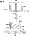
- Fig. 16 illustrates the operation of the sensor cartridge 1500 as shown in Fig. 15 .
- a portion of an insertion mechanism 1600 is shown as being attached to the mechanical adapter 1510.
- the mechanical adapter has been used to drive the insertion needle 106 through the surface 1604 of a subject.
- a sensor mounting unit 1602 is attached to the surface of the subject 1604.
- a sensor 108 has been inserted into the subject and the electrical connection 112 goes back to the sensor connector 110.
- the septum 1508 is left in place and is connected to the sensor mounting unit 1602.
- the insertion needle 106 is withdrawn 1608.
- the retraction of the insertion mechanism 1600 causes the insertion needle 106 to be withdrawn back into the tube 1502.
Landscapes
- Health & Medical Sciences (AREA)
- Life Sciences & Earth Sciences (AREA)
- Physics & Mathematics (AREA)
- Surgery (AREA)
- Public Health (AREA)
- Animal Behavior & Ethology (AREA)
- Pathology (AREA)
- Engineering & Computer Science (AREA)
- Biomedical Technology (AREA)
- Heart & Thoracic Surgery (AREA)
- Medical Informatics (AREA)
- Molecular Biology (AREA)
- Veterinary Medicine (AREA)
- General Health & Medical Sciences (AREA)
- Biophysics (AREA)
- Optics & Photonics (AREA)
- Chemical & Material Sciences (AREA)
- Chemical Kinetics & Catalysis (AREA)
- General Chemical & Material Sciences (AREA)
- Emergency Medicine (AREA)
- Nuclear Medicine, Radiotherapy & Molecular Imaging (AREA)
- Measurement Of The Respiration, Hearing Ability, Form, And Blood Characteristics Of Living Organisms (AREA)
- Infusion, Injection, And Reservoir Apparatuses (AREA)
Claims (8)
- Sensorpatrone (100, 400, 500, 800, 900, 1000, 1300, 1400, 1500), die Folgendes aufweist:- eine sterile Kapsel (104);- einen Sensor (108) innerhalb der sterilen Kapsel, wobei der Sensor innerhalb der sterilen Kapsel liegt;- einen Sensorverbinder (120), der mit dem Sensor in einer Ausgangsposition (122) verbunden ist;- eine Einführnadel (106) zum Einrühren des Sensors in ein Subjekt (114), wobei die Einführungsnadel innerhalb der sterilen Kapsel ist, wobei der Sensor innerhalb der Einführungsnadel ist;- eine Sensormontageeinheit (110) zum Sichern des Sensorverbinders an einer montierten Position (124), wobei die Sensormontageeinheit eine Klebefläche (116) zur Anbringung an einer Außenfläche des Subjekts aufweist, wobei die Sensormontageeinheit zur Aufnahme des Sensorverbinders an der montierten Position funktionell ist, wobei die Sensormontageeinheit einen unteren Teil der sterilen Kapsel bildet; und- einen Einführungsmechanismus (118), der zum Betätigen der Einführnadel und zum Bewegen des Sensorverbinders von der Ausgangsposition (122) zur montierten Position und zum Zurückziehen der Nadel, wobei der Sensor in dem Subjekt zurück-und der Sensorverbinder in der arretierten Position gelassen wird, funktionell ist.
- Sensorpatrone nach Anspruch 1, wobei die Sensorpatrone ferner einen Knopf (1004) aufweist, wobei der Einführungsmechanismus funktionell ist, um bei Drehen (1006) des Knopfs die Einführnadel in einer linearen Richtung (1010, 1012) zu betätigen.
- Sensorpatrone nach einem der vorhergehenden Ansprüche, wobei die Sensormontageeinheit an dem Einführungsmechanismus angebracht ist, wobei die Sensormontageeinheit von dem Einführungsmechanismus abtrennbar ist, wobei der Einführungsmechanismus zum Abtrennen der Sensormontageeinheit von dem Einführungsmechanismus an einem vorbestimmten Punkt bei der Betätigung der Einführnadel funktionell ist.
- Sensorpatrone nach Anspruch 1, 2 oder 3, wobei die Sensorpatrone ferner einen Druckbehälter (802) zum Bilden der sterilen Kapsel aufweist, wobei ein Druckunterschied zwischen dem Druckbehälter und außerhalb der Sensorpatrone zum Anbringen des Einführungsmechanismus an der Montageeinheit funktionell ist, wobei die Sensorpatrone ferner eine Dichtung (804) zur Erhaltung des Druckunterschieds aufweist und wobei der Einführungsmechanismus funktionell ist, um die Dichtung und/oder ein Ventil (808) der Sensorpatrone zum Aufheben des Druckunterschieds während der Betätigung des Einführungsmechanismus zu veranlassen.
- Sensorpatrone nach einem der vorhergehenden Ansprüche, wobei die sterile Kapsel ein Hohlraum (104) ist, wobei der Einführungsmechanismus einen Kolben (1510) aufweist, wobei der Einführungsmechanismus zum Schieben des Kolbens in den Hohlraum zur Betätigung des Einführungsmechanismus zum Treiben der Einführnadel in das Subjekt funktionell ist, wobei der Einführungsmechanismus ferner unter Verwendung des Kolbens zum Zurückziehen der Einführungsnadel in den Hohlraum nach der Einführung der Sensorkapsel in das Subjekt funktionell ist.
- Sensorpatrone nach einem der vorhergehenden Ansprüche, wobei der Einführungsmechanismus eine Sicherung (600) aufweist, die durch Bewegen (700) von einer funktionsfähigen Position auf eine nicht funktionsfähige Position funktionell ist, und wobei der Einführungsmechanismus die Betätigung der Nadel verhindert, wenn die Sicherung in der nicht funktionsfähigen Position ist, und wobei der Einführungsmechanismus die Betätigung der Nadel ermöglicht, wenn die Sicherung in der funktionsfähigen Position ist.
- Sensorpatrone nach einem der vorhergehenden Ansprüche, wobei der Einführungsmechanismus zum Koppeln mit einem Hilfemechanismus (204) einer Einführvorrichtung funktionell ist, wobei der Hilfemechanismus zur Betätigung des Einführungsmechanismus funktionell ist.
- Sensorpatrone nach einem der vorhergehenden Ansprüche, wobei der Einführungsmechanismus ferner funktionell ist, um die Einführnadel nach der Betätigung der Einführnadel und dem Bewegen des Sensors von der Ausgangsposition auf die montierte Position in die sterile Kapsel zurückzuziehen.
Priority Applications (2)
| Application Number | Priority Date | Filing Date | Title |
|---|---|---|---|
| EP13723795.4A EP2854638B1 (de) | 2012-05-31 | 2013-05-21 | Sensorpatrone |
| SI201330194A SI2854638T1 (sl) | 2012-05-31 | 2013-05-21 | Kartuša senzorja |
Applications Claiming Priority (3)
| Application Number | Priority Date | Filing Date | Title |
|---|---|---|---|
| EP12170224.5A EP2668902A1 (de) | 2012-05-31 | 2012-05-31 | Sensorpatrone und Inserter |
| EP13723795.4A EP2854638B1 (de) | 2012-05-31 | 2013-05-21 | Sensorpatrone |
| PCT/EP2013/060364 WO2013178499A1 (en) | 2012-05-31 | 2013-05-21 | Sensor cartridge and inserter |
Publications (2)
| Publication Number | Publication Date |
|---|---|
| EP2854638A1 EP2854638A1 (de) | 2015-04-08 |
| EP2854638B1 true EP2854638B1 (de) | 2016-04-06 |
Family
ID=48468319
Family Applications (2)
| Application Number | Title | Priority Date | Filing Date |
|---|---|---|---|
| EP12170224.5A Withdrawn EP2668902A1 (de) | 2012-05-31 | 2012-05-31 | Sensorpatrone und Inserter |
| EP13723795.4A Active EP2854638B1 (de) | 2012-05-31 | 2013-05-21 | Sensorpatrone |
Family Applications Before (1)
| Application Number | Title | Priority Date | Filing Date |
|---|---|---|---|
| EP12170224.5A Withdrawn EP2668902A1 (de) | 2012-05-31 | 2012-05-31 | Sensorpatrone und Inserter |
Country Status (9)
| Country | Link |
|---|---|
| US (1) | US9883888B2 (de) |
| EP (2) | EP2668902A1 (de) |
| CN (1) | CN104507388B (de) |
| CA (1) | CA2870243C (de) |
| DK (1) | DK2854638T3 (de) |
| PL (1) | PL2854638T3 (de) |
| RU (1) | RU2608234C2 (de) |
| SI (1) | SI2854638T1 (de) |
| WO (1) | WO2013178499A1 (de) |
Cited By (1)
| Publication number | Priority date | Publication date | Assignee | Title |
|---|---|---|---|---|
| WO2025149300A1 (en) | 2024-01-10 | 2025-07-17 | Roche Diabetes Care Gmbh | Continuous analyte monitoring unit |
Families Citing this family (15)
| Publication number | Priority date | Publication date | Assignee | Title |
|---|---|---|---|---|
| US10463306B2 (en) | 2014-05-15 | 2019-11-05 | Novalung Gmbh | Medical measuring system and method for production of the measuring system |
| EP3590564B1 (de) * | 2014-05-15 | 2025-05-14 | Xenios AG | Medizintechnische messvorrichtung und mess-verfahren |
| EP3237058B1 (de) * | 2014-12-23 | 2022-02-16 | The Regents of The University of California | Zusammensetzungen und systeme zur vorrichtungsimplantation |
| EP3159026A1 (de) | 2015-10-23 | 2017-04-26 | novalung GmbH | Zwischenelement für eine medizintechnische extrakorporale fluidleitung, medizintechnisches extrakorporales fluidsystem und verfahren zum messen eines in einem medizintechnischen extrakorporalen fluidsystem geführten fluid des menschlichen oder tierischen körpers enthaltenen gases |
| ES2698519T3 (es) | 2016-01-29 | 2019-02-05 | Hoffmann La Roche | Envase médico funcional y dispositivo médico para insertar al menos un subsistema en un huésped |
| US11058329B2 (en) | 2016-10-31 | 2021-07-13 | Dexcom, Inc. | Transcutaneous analyte sensor systems and methods |
| CN109745228A (zh) * | 2019-01-24 | 2019-05-14 | 潍坊学院 | 一种用于糖尿病的针灸针组 |
| JP7102469B2 (ja) * | 2019-08-02 | 2022-07-19 | 華廣生技股▲ふん▼有限公司 | センサーを搭載するための容器及びその操作方法 |
| WO2021031057A1 (en) * | 2019-08-19 | 2021-02-25 | Medtrum Technologies Inc. | Sensing device |
| US20230051653A1 (en) * | 2020-02-05 | 2023-02-16 | Bruno Pierre Henri BINET | Accessory for making and coupling a flow path between a package and a tester |
| WO2021164182A1 (en) * | 2020-02-20 | 2021-08-26 | Medtrum Technologies Inc. | A mounting unit of an analyte detection device and a mounting method thereof |
| US11672965B2 (en) * | 2021-09-28 | 2023-06-13 | Biolinq Incorporated | Microneedle enclosure and applicator device for microneedle array based continuous analyte monitoring device |
| CA3251154A1 (en) * | 2022-06-09 | 2023-12-14 | Vital Biosciences Inc. | BLOOD COLLECTION DEVICE |
| CA3268251A1 (en) | 2022-10-21 | 2024-04-25 | F. Hoffmann-La Roche Ag | MEDICAL DEVICE INSERTION SYSTEM AND METHOD |
| CN121891000B (zh) * | 2026-03-26 | 2026-07-14 | 三诺生物传感股份有限公司 | 一种密封结构及植入工具 |
Family Cites Families (21)
| Publication number | Priority date | Publication date | Assignee | Title |
|---|---|---|---|---|
| US5390671A (en) * | 1994-03-15 | 1995-02-21 | Minimed Inc. | Transcutaneous sensor insertion set |
| US7381184B2 (en) * | 2002-11-05 | 2008-06-03 | Abbott Diabetes Care Inc. | Sensor inserter assembly |
| US8615282B2 (en) * | 2004-07-13 | 2013-12-24 | Dexcom, Inc. | Analyte sensor |
| US7946984B2 (en) * | 2004-07-13 | 2011-05-24 | Dexcom, Inc. | Transcutaneous analyte sensor |
| US9788771B2 (en) * | 2006-10-23 | 2017-10-17 | Abbott Diabetes Care Inc. | Variable speed sensor insertion devices and methods of use |
| US20100331646A1 (en) * | 2009-06-30 | 2010-12-30 | Abbott Diabetes Care Inc. | Health Management Devices and Methods |
| US7883464B2 (en) * | 2005-09-30 | 2011-02-08 | Abbott Diabetes Care Inc. | Integrated transmitter unit and sensor introducer mechanism and methods of use |
| US20110190603A1 (en) * | 2009-09-29 | 2011-08-04 | Stafford Gary A | Sensor Inserter Having Introducer |
| US7697967B2 (en) * | 2005-12-28 | 2010-04-13 | Abbott Diabetes Care Inc. | Method and apparatus for providing analyte sensor insertion |
| US8545403B2 (en) * | 2005-12-28 | 2013-10-01 | Abbott Diabetes Care Inc. | Medical device insertion |
| US8696570B2 (en) * | 2006-11-28 | 2014-04-15 | Roche Diagnostics Operations Inc. | Insertion device and method for inserting a subcutaneously insertable element into body |
| EP1972267A1 (de) | 2007-03-20 | 2008-09-24 | Roche Diagnostics GmbH | System zur in-vivo Messung einer Analytkonzentration |
| US8002752B2 (en) * | 2007-06-25 | 2011-08-23 | Medingo, Ltd. | Protector apparatus |
| AU2008281383A1 (en) * | 2007-08-01 | 2009-02-05 | F.Hoffmann-La Roche Ag | Device for facilitating infusion of therapeutic fluids and sensing of bodily analytes |
| EP2039607A1 (de) | 2007-09-19 | 2009-03-25 | Roche Diagnostics GmbH | Verbindungsfolien mit Laser für sterile Lanzetten |
| US9295786B2 (en) * | 2008-05-28 | 2016-03-29 | Medtronic Minimed, Inc. | Needle protective device for subcutaneous sensors |
| RU83694U1 (ru) * | 2008-06-11 | 2009-06-20 | Общество с ограниченной ответственностью "Медицинская электроника" | Устройство для измерения концентрации глюкозы в крови |
| DE102008053216A1 (de) * | 2008-10-25 | 2010-05-06 | IHP GmbH - Innovations for High Performance Institut für innovative Mikroelektronik | Anordnung für einen transdermalen Sensor zur Erfassung und drahtlosen Übertragung von Messgrößen des Unterhautfettgewebes |
| US8758267B2 (en) * | 2009-03-17 | 2014-06-24 | Nova Biomedical Corporation | Modified lancet carrier for single-use lancet sensor assembly |
| ES2884623T3 (es) * | 2009-07-23 | 2021-12-10 | Abbott Diabetes Care Inc | Procedimiento de fabricación y sistema de medición continua de analitos |
| JP5748595B2 (ja) * | 2010-08-30 | 2015-07-15 | アークレイ株式会社 | センサ挿入・回収装置 |
-
2012
- 2012-05-31 EP EP12170224.5A patent/EP2668902A1/de not_active Withdrawn
-
2013
- 2013-05-21 RU RU2014143413A patent/RU2608234C2/ru active
- 2013-05-21 DK DK13723795.4T patent/DK2854638T3/en active
- 2013-05-21 SI SI201330194A patent/SI2854638T1/sl unknown
- 2013-05-21 PL PL13723795.4T patent/PL2854638T3/pl unknown
- 2013-05-21 WO PCT/EP2013/060364 patent/WO2013178499A1/en not_active Ceased
- 2013-05-21 EP EP13723795.4A patent/EP2854638B1/de active Active
- 2013-05-21 CA CA2870243A patent/CA2870243C/en active Active
- 2013-05-21 CN CN201380025965.XA patent/CN104507388B/zh active Active
-
2014
- 2014-11-26 US US14/554,304 patent/US9883888B2/en active Active
Cited By (1)
| Publication number | Priority date | Publication date | Assignee | Title |
|---|---|---|---|---|
| WO2025149300A1 (en) | 2024-01-10 | 2025-07-17 | Roche Diabetes Care Gmbh | Continuous analyte monitoring unit |
Also Published As
| Publication number | Publication date |
|---|---|
| CN104507388A (zh) | 2015-04-08 |
| DK2854638T3 (en) | 2016-05-09 |
| HK1209011A1 (en) | 2016-03-24 |
| US20150080690A1 (en) | 2015-03-19 |
| CA2870243A1 (en) | 2013-12-05 |
| CN104507388B (zh) | 2016-12-28 |
| EP2854638A1 (de) | 2015-04-08 |
| RU2014143413A (ru) | 2016-07-20 |
| US9883888B2 (en) | 2018-02-06 |
| WO2013178499A1 (en) | 2013-12-05 |
| SI2854638T1 (sl) | 2016-07-29 |
| EP2668902A1 (de) | 2013-12-04 |
| CA2870243C (en) | 2017-03-07 |
| PL2854638T3 (pl) | 2016-09-30 |
| RU2608234C2 (ru) | 2017-01-17 |
Similar Documents
| Publication | Publication Date | Title |
|---|---|---|
| US9883888B2 (en) | Sensor cartridge and inserter | |
| EP2854639B1 (de) | Sensoreinführanordnung mit sensorpatrone und inserter | |
| JP3672553B2 (ja) | 採血用システム | |
| US6997913B2 (en) | Needle safety device | |
| KR100197578B1 (ko) | 후퇴가능한 주사바늘을 지니는 주사기 | |
| US20220202446A1 (en) | Reusable applicators for transcutaneous analyte sensors, and associated methods | |
| JP5970374B2 (ja) | シール型ルアー取付部を有する注入デバイス | |
| JP2022172329A (ja) | 医療システムおよびその製造方法 | |
| EP2982302A1 (de) | Medizinischer Applikator | |
| EP1316325A1 (de) | Nadelschutzvorrichtung | |
| CN105263413B (zh) | 体液采样元件 | |
| EP4335367B1 (de) | Wiederverwendbare vorrichtung zum einsatz transkutaner sensoren und zugehörige technologie | |
| HK1209011B (en) | Sensor cartridge and inserter | |
| US20250241679A1 (en) | Insertion system and method for inserting a medical device | |
| JP5169218B2 (ja) | シリンジ | |
| CN121489467A (zh) | 助针器 | |
| HK1201219B (en) | Subcutaneous needle insertion mechanism | |
| HK1201219A1 (zh) | 皮下针插入机构 |
Legal Events
| Date | Code | Title | Description |
|---|---|---|---|
| PUAI | Public reference made under article 153(3) epc to a published international application that has entered the european phase |
Free format text: ORIGINAL CODE: 0009012 |
|
| 17P | Request for examination filed |
Effective date: 20150105 |
|
| AK | Designated contracting states |
Kind code of ref document: A1 Designated state(s): AL AT BE BG CH CY CZ DE DK EE ES FI FR GB GR HR HU IE IS IT LI LT LU LV MC MK MT NL NO PL PT RO RS SE SI SK SM TR |
|
| AX | Request for extension of the european patent |
Extension state: BA ME |
|
| RIN1 | Information on inventor provided before grant (corrected) |
Inventor name: KUBE, OLIVER Inventor name: FREY, STEPHAN-MICHAEL Inventor name: WALTER, HELMUT Inventor name: HECK, WOLFGANG |
|
| DAX | Request for extension of the european patent (deleted) | ||
| GRAP | Despatch of communication of intention to grant a patent |
Free format text: ORIGINAL CODE: EPIDOSNIGR1 |
|
| RIC1 | Information provided on ipc code assigned before grant |
Ipc: A61B 5/00 20060101ALI20151001BHEP Ipc: A61B 5/145 20060101AFI20151001BHEP Ipc: A61B 5/1486 20060101ALI20151001BHEP |
|
| INTG | Intention to grant announced |
Effective date: 20151030 |
|
| GRAS | Grant fee paid |
Free format text: ORIGINAL CODE: EPIDOSNIGR3 |
|
| GRAA | (expected) grant |
Free format text: ORIGINAL CODE: 0009210 |
|
| AK | Designated contracting states |
Kind code of ref document: B1 Designated state(s): AL AT BE BG CH CY CZ DE DK EE ES FI FR GB GR HR HU IE IS IT LI LT LU LV MC MK MT NL NO PL PT RO RS SE SI SK SM TR |
|
| REG | Reference to a national code |
Ref country code: GB Ref legal event code: FG4D |
|
| REG | Reference to a national code |
Ref country code: AT Ref legal event code: REF Ref document number: 786818 Country of ref document: AT Kind code of ref document: T Effective date: 20160415 Ref country code: CH Ref legal event code: EP |
|
| REG | Reference to a national code |
Ref country code: IE Ref legal event code: FG4D |
|
| REG | Reference to a national code |
Ref country code: DK Ref legal event code: T3 Effective date: 20160504 |
|
| REG | Reference to a national code |
Ref country code: DE Ref legal event code: R096 Ref document number: 602013006303 Country of ref document: DE |
|
| REG | Reference to a national code |
Ref country code: FR Ref legal event code: PLFP Year of fee payment: 4 |
|
| REG | Reference to a national code |
Ref country code: NL Ref legal event code: FP |
|
| REG | Reference to a national code |
Ref country code: SE Ref legal event code: TRGR |
|
| REG | Reference to a national code |
Ref country code: LT Ref legal event code: MG4D |
|
| REG | Reference to a national code |
Ref country code: AT Ref legal event code: MK05 Ref document number: 786818 Country of ref document: AT Kind code of ref document: T Effective date: 20160406 |
|
| REG | Reference to a national code |
Ref country code: NO Ref legal event code: T2 Effective date: 20160406 |
|
| PG25 | Lapsed in a contracting state [announced via postgrant information from national office to epo] |
Ref country code: BE Free format text: LAPSE BECAUSE OF NON-PAYMENT OF DUE FEES Effective date: 20160531 |
|
| PG25 | Lapsed in a contracting state [announced via postgrant information from national office to epo] |
Ref country code: FI Free format text: LAPSE BECAUSE OF FAILURE TO SUBMIT A TRANSLATION OF THE DESCRIPTION OR TO PAY THE FEE WITHIN THE PRESCRIBED TIME-LIMIT Effective date: 20160406 Ref country code: LT Free format text: LAPSE BECAUSE OF FAILURE TO SUBMIT A TRANSLATION OF THE DESCRIPTION OR TO PAY THE FEE WITHIN THE PRESCRIBED TIME-LIMIT Effective date: 20160406 Ref country code: IS Free format text: LAPSE BECAUSE OF FAILURE TO SUBMIT A TRANSLATION OF THE DESCRIPTION OR TO PAY THE FEE WITHIN THE PRESCRIBED TIME-LIMIT Effective date: 20160806 |
|
| PG25 | Lapsed in a contracting state [announced via postgrant information from national office to epo] |
Ref country code: RS Free format text: LAPSE BECAUSE OF FAILURE TO SUBMIT A TRANSLATION OF THE DESCRIPTION OR TO PAY THE FEE WITHIN THE PRESCRIBED TIME-LIMIT Effective date: 20160406 Ref country code: HR Free format text: LAPSE BECAUSE OF FAILURE TO SUBMIT A TRANSLATION OF THE DESCRIPTION OR TO PAY THE FEE WITHIN THE PRESCRIBED TIME-LIMIT Effective date: 20160406 Ref country code: PT Free format text: LAPSE BECAUSE OF FAILURE TO SUBMIT A TRANSLATION OF THE DESCRIPTION OR TO PAY THE FEE WITHIN THE PRESCRIBED TIME-LIMIT Effective date: 20160808 Ref country code: GR Free format text: LAPSE BECAUSE OF FAILURE TO SUBMIT A TRANSLATION OF THE DESCRIPTION OR TO PAY THE FEE WITHIN THE PRESCRIBED TIME-LIMIT Effective date: 20160707 Ref country code: AT Free format text: LAPSE BECAUSE OF FAILURE TO SUBMIT A TRANSLATION OF THE DESCRIPTION OR TO PAY THE FEE WITHIN THE PRESCRIBED TIME-LIMIT Effective date: 20160406 Ref country code: ES Free format text: LAPSE BECAUSE OF FAILURE TO SUBMIT A TRANSLATION OF THE DESCRIPTION OR TO PAY THE FEE WITHIN THE PRESCRIBED TIME-LIMIT Effective date: 20160406 Ref country code: LV Free format text: LAPSE BECAUSE OF FAILURE TO SUBMIT A TRANSLATION OF THE DESCRIPTION OR TO PAY THE FEE WITHIN THE PRESCRIBED TIME-LIMIT Effective date: 20160406 |
|
| PG25 | Lapsed in a contracting state [announced via postgrant information from national office to epo] |
Ref country code: BE Free format text: LAPSE BECAUSE OF FAILURE TO SUBMIT A TRANSLATION OF THE DESCRIPTION OR TO PAY THE FEE WITHIN THE PRESCRIBED TIME-LIMIT Effective date: 20160406 |
|
| REG | Reference to a national code |
Ref country code: DE Ref legal event code: R097 Ref document number: 602013006303 Country of ref document: DE |
|
| PG25 | Lapsed in a contracting state [announced via postgrant information from national office to epo] |
Ref country code: EE Free format text: LAPSE BECAUSE OF FAILURE TO SUBMIT A TRANSLATION OF THE DESCRIPTION OR TO PAY THE FEE WITHIN THE PRESCRIBED TIME-LIMIT Effective date: 20160406 Ref country code: RO Free format text: LAPSE BECAUSE OF FAILURE TO SUBMIT A TRANSLATION OF THE DESCRIPTION OR TO PAY THE FEE WITHIN THE PRESCRIBED TIME-LIMIT Effective date: 20160406 Ref country code: SK Free format text: LAPSE BECAUSE OF FAILURE TO SUBMIT A TRANSLATION OF THE DESCRIPTION OR TO PAY THE FEE WITHIN THE PRESCRIBED TIME-LIMIT Effective date: 20160406 Ref country code: MC Free format text: LAPSE BECAUSE OF FAILURE TO SUBMIT A TRANSLATION OF THE DESCRIPTION OR TO PAY THE FEE WITHIN THE PRESCRIBED TIME-LIMIT Effective date: 20160406 |
|
| PLBE | No opposition filed within time limit |
Free format text: ORIGINAL CODE: 0009261 |
|
| STAA | Information on the status of an ep patent application or granted ep patent |
Free format text: STATUS: NO OPPOSITION FILED WITHIN TIME LIMIT |
|
| REG | Reference to a national code |
Ref country code: IE Ref legal event code: MM4A |
|
| PG25 | Lapsed in a contracting state [announced via postgrant information from national office to epo] |
Ref country code: SM Free format text: LAPSE BECAUSE OF FAILURE TO SUBMIT A TRANSLATION OF THE DESCRIPTION OR TO PAY THE FEE WITHIN THE PRESCRIBED TIME-LIMIT Effective date: 20160406 |
|
| 26N | No opposition filed |
Effective date: 20170110 |
|
| REG | Reference to a national code |
Ref country code: FR Ref legal event code: PLFP Year of fee payment: 5 |
|
| PG25 | Lapsed in a contracting state [announced via postgrant information from national office to epo] |
Ref country code: IE Free format text: LAPSE BECAUSE OF NON-PAYMENT OF DUE FEES Effective date: 20160521 |
|
| REG | Reference to a national code |
Ref country code: FR Ref legal event code: PLFP Year of fee payment: 6 |
|
| PG25 | Lapsed in a contracting state [announced via postgrant information from national office to epo] |
Ref country code: HU Free format text: LAPSE BECAUSE OF FAILURE TO SUBMIT A TRANSLATION OF THE DESCRIPTION OR TO PAY THE FEE WITHIN THE PRESCRIBED TIME-LIMIT; INVALID AB INITIO Effective date: 20130521 |
|
| PG25 | Lapsed in a contracting state [announced via postgrant information from national office to epo] |
Ref country code: MT Free format text: LAPSE BECAUSE OF NON-PAYMENT OF DUE FEES Effective date: 20160531 Ref country code: CY Free format text: LAPSE BECAUSE OF FAILURE TO SUBMIT A TRANSLATION OF THE DESCRIPTION OR TO PAY THE FEE WITHIN THE PRESCRIBED TIME-LIMIT Effective date: 20160406 Ref country code: LU Free format text: LAPSE BECAUSE OF NON-PAYMENT OF DUE FEES Effective date: 20160521 Ref country code: MK Free format text: LAPSE BECAUSE OF FAILURE TO SUBMIT A TRANSLATION OF THE DESCRIPTION OR TO PAY THE FEE WITHIN THE PRESCRIBED TIME-LIMIT Effective date: 20160406 |
|
| PG25 | Lapsed in a contracting state [announced via postgrant information from national office to epo] |
Ref country code: BG Free format text: LAPSE BECAUSE OF FAILURE TO SUBMIT A TRANSLATION OF THE DESCRIPTION OR TO PAY THE FEE WITHIN THE PRESCRIBED TIME-LIMIT Effective date: 20160406 |
|
| PG25 | Lapsed in a contracting state [announced via postgrant information from national office to epo] |
Ref country code: AL Free format text: LAPSE BECAUSE OF FAILURE TO SUBMIT A TRANSLATION OF THE DESCRIPTION OR TO PAY THE FEE WITHIN THE PRESCRIBED TIME-LIMIT Effective date: 20160406 Ref country code: TR Free format text: LAPSE BECAUSE OF FAILURE TO SUBMIT A TRANSLATION OF THE DESCRIPTION OR TO PAY THE FEE WITHIN THE PRESCRIBED TIME-LIMIT Effective date: 20160406 |
|
| PGFP | Annual fee paid to national office [announced via postgrant information from national office to epo] |
Ref country code: PL Payment date: 20220328 Year of fee payment: 10 |
|
| PGFP | Annual fee paid to national office [announced via postgrant information from national office to epo] |
Ref country code: NL Payment date: 20220414 Year of fee payment: 10 |
|
| PGFP | Annual fee paid to national office [announced via postgrant information from national office to epo] |
Ref country code: NO Payment date: 20220425 Year of fee payment: 10 Ref country code: DK Payment date: 20220425 Year of fee payment: 10 Ref country code: CZ Payment date: 20220419 Year of fee payment: 10 |
|
| PGFP | Annual fee paid to national office [announced via postgrant information from national office to epo] |
Ref country code: SI Payment date: 20220427 Year of fee payment: 10 Ref country code: CH Payment date: 20220413 Year of fee payment: 10 |
|
| REG | Reference to a national code |
Ref country code: FR Ref legal event code: PLFP Year of fee payment: 11 |
|
| REG | Reference to a national code |
Ref country code: NO Ref legal event code: MMEP |
|
| REG | Reference to a national code |
Ref country code: CH Ref legal event code: PL |
|
| REG | Reference to a national code |
Ref country code: DK Ref legal event code: EBP Effective date: 20230531 |
|
| REG | Reference to a national code |
Ref country code: NL Ref legal event code: MM Effective date: 20230601 |
|
| PG25 | Lapsed in a contracting state [announced via postgrant information from national office to epo] |
Ref country code: SI Free format text: LAPSE BECAUSE OF NON-PAYMENT OF DUE FEES Effective date: 20230522 Ref country code: NO Free format text: LAPSE BECAUSE OF NON-PAYMENT OF DUE FEES Effective date: 20230531 Ref country code: LI Free format text: LAPSE BECAUSE OF NON-PAYMENT OF DUE FEES Effective date: 20230531 Ref country code: CZ Free format text: LAPSE BECAUSE OF NON-PAYMENT OF DUE FEES Effective date: 20230521 Ref country code: CH Free format text: LAPSE BECAUSE OF NON-PAYMENT OF DUE FEES Effective date: 20230531 |
|
| PG25 | Lapsed in a contracting state [announced via postgrant information from national office to epo] |
Ref country code: NL Free format text: LAPSE BECAUSE OF NON-PAYMENT OF DUE FEES Effective date: 20230601 |
|
| REG | Reference to a national code |
Ref country code: SI Ref legal event code: KO00 Effective date: 20240227 |
|
| PG25 | Lapsed in a contracting state [announced via postgrant information from national office to epo] |
Ref country code: DK Free format text: LAPSE BECAUSE OF NON-PAYMENT OF DUE FEES Effective date: 20230531 |
|
| PG25 | Lapsed in a contracting state [announced via postgrant information from national office to epo] |
Ref country code: PL Free format text: LAPSE BECAUSE OF NON-PAYMENT OF DUE FEES Effective date: 20230521 |
|
| PG25 | Lapsed in a contracting state [announced via postgrant information from national office to epo] |
Ref country code: PL Free format text: LAPSE BECAUSE OF NON-PAYMENT OF DUE FEES Effective date: 20230521 |
|
| PGFP | Annual fee paid to national office [announced via postgrant information from national office to epo] |
Ref country code: GB Payment date: 20260317 Year of fee payment: 14 |
|
| PGFP | Annual fee paid to national office [announced via postgrant information from national office to epo] |
Ref country code: IT Payment date: 20260421 Year of fee payment: 14 |
|
| PGFP | Annual fee paid to national office [announced via postgrant information from national office to epo] |
Ref country code: DE Payment date: 20260421 Year of fee payment: 14 |
|
| PGFP | Annual fee paid to national office [announced via postgrant information from national office to epo] |
Ref country code: SE Payment date: 20260421 Year of fee payment: 14 |
|
| PGFP | Annual fee paid to national office [announced via postgrant information from national office to epo] |
Ref country code: FR Payment date: 20260422 Year of fee payment: 14 |