EP2855101B1 - Outil - Google Patents
Outil Download PDFInfo
- Publication number
- EP2855101B1 EP2855101B1 EP13722441.6A EP13722441A EP2855101B1 EP 2855101 B1 EP2855101 B1 EP 2855101B1 EP 13722441 A EP13722441 A EP 13722441A EP 2855101 B1 EP2855101 B1 EP 2855101B1
- Authority
- EP
- European Patent Office
- Prior art keywords
- adapter
- accumulator
- device shaft
- tool according
- tool
- Prior art date
- Legal status (The legal status is an assumption and is not a legal conclusion. Google has not performed a legal analysis and makes no representation as to the accuracy of the status listed.)
- Active
Links
Images






Classifications
-
- B—PERFORMING OPERATIONS; TRANSPORTING
- B25—HAND TOOLS; PORTABLE POWER-DRIVEN TOOLS; MANIPULATORS
- B25F—COMBINATION OR MULTI-PURPOSE TOOLS NOT OTHERWISE PROVIDED FOR; DETAILS OR COMPONENTS OF PORTABLE POWER-DRIVEN TOOLS NOT PARTICULARLY RELATED TO THE OPERATIONS PERFORMED AND NOT OTHERWISE PROVIDED FOR
- B25F5/00—Details or components of portable power-driven tools not particularly related to the operations performed and not otherwise provided for
-
- B—PERFORMING OPERATIONS; TRANSPORTING
- B23—MACHINE TOOLS; METAL-WORKING NOT OTHERWISE PROVIDED FOR
- B23Q—DETAILS, COMPONENTS, OR ACCESSORIES FOR MACHINE TOOLS, e.g. ARRANGEMENTS FOR COPYING OR CONTROLLING; MACHINE TOOLS IN GENERAL CHARACTERISED BY THE CONSTRUCTION OF PARTICULAR DETAILS OR COMPONENTS; COMBINATIONS OR ASSOCIATIONS OF METAL-WORKING MACHINES, NOT DIRECTED TO A PARTICULAR RESULT
- B23Q17/00—Arrangements for observing, indicating or measuring on machine tools
- B23Q17/007—Arrangements for observing, indicating or measuring on machine tools for managing machine functions not concerning the tool
Definitions
- the invention relates to a hydraulic or electric motor-driven tool according to the features of the preamble of claim 1 and a method for operating a hydraulic or electric motor tool according to the features of the preamble of claim 10.
- Tools of this type in particular in the form of tools operated hydraulically or by an electric motor, are already known in many respects. For example, it will refer to the WO 99/19947 A or the U.S. 6,532,790 B2 , the WO 03/084719 A2 or the U.S. 7,254,982 B2 referred.
- the invention is concerned with the task of specifying a favorable connection of an adapter with a device shaft of a device of this type.
- the adapter provided between the equipment shaft and the accumulator can be secured to the equipment shaft and the accumulator by means of a snap-in connection.
- the solution shown is advantageous, for example, if a device manufacturer wants to design the devices with regard to several possible accumulators according to customer requirements, but on the other hand a customer also wants to continue working with a once selected accumulator.
- the adapter should not be removed if possible in order to avoid faults.
- the accumulators also have contacts with which certain information from the accumulator can be called up and evaluated in the device. about the state of charge and/or the temperature of the accumulator. Such information can also be important in a charger, for example, and can be read out there via the contacts mentioned.
- the adapter has contacts on its side facing the accumulator for recording and possibly transmitting values relating to the temperature and/or the state of charge, possibly also with regard to individual cells of the accumulator. If these contacts are only formed on the side of the accumulator, an evaluation circuit can already be provided in the adapter itself, which also has display means with which, for example, an impermissible temperature and/or a certain state of charge or that the state of charge falls below a certain state of charge is indicated to the outside becomes.
- Values can be transmitted via standard electrical conductors. However, it can also be done optically, magnetically, by radio and/or mechanically, at least in part.
- the adapter be designed to interrupt a power supply to the pressing device. This is particularly important if, as already mentioned, an impermissibly high temperature is detected with regard to the accumulator and/or a temperature rise that indicates that an impermissibly high temperature is likely to be reached and/or if a short circuit is detected and/or or possible other events that indicate an immediate disconnection of the power supply to the tool.
- the adapter In addition to its function of connecting the rechargeable battery to the device via different interfaces, the adapter is also designed to assume a safety function.
- the adapter can be docked to a charger together with the battery that is connected, in such a way that the battery is connected to the charger by means of the adapter.
- the adapter is used here to transfer the charging current from the charger to the accumulator for charging the same.
- the circuit breaker is further preferably designed in such a way that it switches automatically depending on a status data item of the accumulator.
- status data can be a temperature detected in the accumulator and/or a state of charge of the accumulator or the like.
- the adapter is designed to emit a signal, for example a light and/or audio signal is.
- a signal can also be emitted, for example, with regard to a detected increased temperature and/or a detected specific state of charge and/or a short circuit or a similar event.
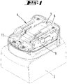
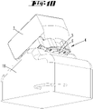
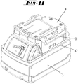
- a tool 1 which has a device shaft 2, with which a battery 3 can be connected by means of an adapter 4.
- the adapter 4 can be adapted to the configuration of a first rechargeable battery 3 be.
- the equipment shaft 2 can be adapted to the configuration of a second accumulator 3, which can then be connected directly to the equipment shaft 2 without the adapter 4.
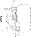
- the adapter 4 is snap-connected to the device shaft 2, as can be seen in more detail from the figures 6 and 7 results.
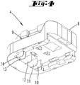
- a release part is preferably provided in the adapter 4, in the exemplary embodiment a snap-in part 5 that can be deflected against spring force—here downwards.
- the latching part 5 is offset inwards relative to an outer wall 6 of the adapter 4 . It is therefore necessary to reach into the interior of the adapter 4 in order to actuate the latching part 5 .
- the outer wall 6 is continuous.
- the adapter 4 used here once in a latching manner cannot be released again without destroying the outer wall 6 .
- the outer wall 6 also has a door or latch opening.
- the adapter 4 shown here is a plug-in adapter. This is slidingly connected to the equipment shaft 2 essentially at right angles to a longitudinal axis L of the equipment shaft 2 .
- a front cover wall 8 of the device shaft represents a sliding stop.
- projections are preferably provided on the inside of the device shaft, which interact with recesses 9 of the adapter, resulting in a rail-like moving together.
- the locking part 5 is the only movable one Part that is required to anchor the adapter 4 to the equipment shaft 2.
- an embodiment in the form of a tower adapter (not shown) is also possible. This is connected to the device in the longitudinal direction of the device shaft 2, usually by being pushed into a receiving space formed on the device shaft.
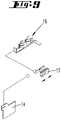
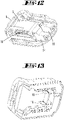
- FIG. 5 reproduces an exploded view of the adapter
- 4 electrical contacts 10 to 14 are arranged inside the adapter, which protrude downwards, are in corresponding contacts of the accumulator in the plugged-in state.
- the electrical currents are passed through to the top of the adapter 4, where corresponding contact elements 15, 16 are arranged.
- Conventional accumulators make such values available at the corresponding contacts.
- the electrical circuit shown can be seen that an interruption of a power supply is possible, this via a switch 17.
- the switch 17 can either be actuated automatically, for example by a measured temperature or other measured data within the adapter and / or by passing the values through first in the Device in which the device, in a microprocessor or the like, is compared with permissible data and depending on this the power interruption is made or not.
- the switch can also be provided so that it can be actuated by hand.
- the adapter is designed to emit a signal, for example a light and/or audio signal.
- the accumulator 3 together with a plug-connected adapter 4, such as in the figures 9 and 10 shown to be chargeable.
- a charger 18 is connected to the accumulator 3 by means of the adapter 4 for charging.
- the adapter 4 in this embodiment has more electrical feed-through contacts than just the two electrical contacts required for the electrical power supply, namely also electrical feed-through contacts relating to the temperature of the accumulator and/or the state of charge of a charging cell of the accumulator, etc.
- Data can also be transmitted alone or in addition, by optical, magnetic, radio or mechanical means.
Landscapes
- Engineering & Computer Science (AREA)
- Mechanical Engineering (AREA)
- Secondary Cells (AREA)
- Charge And Discharge Circuits For Batteries Or The Like (AREA)
Claims (11)
- Outil (1) à fonctionnement hydraulique ou à moteur électrique, par exemple un appareil de pressage, avec un manche d'appareil (2) qui présente au moins un premier et un deuxième contact électrique et avec une batterie (3) pouvant être reliée au manche d'appareil (2) par encliquetage, dans lequel un adaptateur (4) est prévu entre le manche d'appareil (2) et la batterie (3) lequel peut être fixé au manche d'appareil (2) au moyen d'une liaison par encliquetage avec le manche d'appareil (2), l'adaptateur (4) pouvant être fixé à la batterie (3), caractérisé en ce que la liaison par encliquetage de l'adaptateur (4) avec le manche d'appareil (2) ne peut pas être supprimée sans détruire une partie de l'adaptateur (4).
- Outil selon la revendication 1, caractérisé en ce que l'adaptateur (4) est adapté à la configuration d'une première batterie (3) et en ce que le manche d'appareil (2) est adapté à la configuration d'une deuxième batterie (3).
- Outil selon l'une des revendications précédentes, caractérisé en ce que l'adaptateur (4) présente, en tout cas sur son côté tourné vers la batterie (3), des contacts pour la collecte et éventuellement la transmission de valeurs concernant la température et/ou l'état de charge, le cas échéant aussi en ce qui concerne les différentes cellules de la batterie (3).
- Outil selon l'une des revendications précédentes, caractérisé en ce que l'adaptateur (4) est conçu pour interrompre une alimentation de puissance de l'outil.
- Outil selon l'une des revendications précédentes, caractérisé en ce qu'un interrupteur de puissance (17) est agencé dans la batterie (3).
- Outil selon la revendication 5, caractérisé en ce que l'interrupteur de puissance (17) commute automatiquement en fonction d'une donnée d'état de la batterie (3).
- Outil selon l'une des revendications 5 ou 6, caractérisé en ce que l'interrupteur de puissance (17) commute en fonction d'une température et/ou de l'état de charge de la batterie (3).
- Outil selon l'une des revendications précédentes, caractérisé en ce que la batterie (3) est rechargeable avec l'adaptateur (4) relié par enfichage, la batterie (3) étant relié au chargeur (18) au moyen de l'adaptateur (4) .
- Outil selon l'une des revendications précédentes, caractérisé en ce que l'adaptateur (4) est conçu pour émettre un signal, par exemple un signal lumineux et/ou sonore.
- Procédé pour faire fonctionner un outil (1) hydraulique ou à moteur électrique, par exemple un appareil de pressage, avec un manche d'appareil (2) qui présente au moins un premier et un deuxième contact électrique et avec une batterie (3) pouvant être reliée au manche d'appareil (2) par encliquetage, dans lequel un adaptateur (4) est prévu entre le manche d'appareil (2) et la batterie (3) lequel est fixé au manche d'appareil (2) au moyen d'une liaison par encliquetage, l'adaptateur (4) étant fixé à la batterie (3), caractérisé en ce que la liaison par encliquetage n'est pas supprimée sans détruire une partie de l'adaptateur (4).
- Procédé selon la revendication 10, caractérisé en ce que l'adaptateur présente les caractéristiques de l'une des revendications 2 à 8.
Applications Claiming Priority (2)
| Application Number | Priority Date | Filing Date | Title |
|---|---|---|---|
| DE102012104538A DE102012104538A1 (de) | 2012-05-25 | 2012-05-25 | Werkzeug |
| PCT/EP2013/059912 WO2013174675A1 (fr) | 2012-05-25 | 2013-05-14 | Outil |
Publications (2)
| Publication Number | Publication Date |
|---|---|
| EP2855101A1 EP2855101A1 (fr) | 2015-04-08 |
| EP2855101B1 true EP2855101B1 (fr) | 2022-06-22 |
Family
ID=48430792
Family Applications (1)
| Application Number | Title | Priority Date | Filing Date |
|---|---|---|---|
| EP13722441.6A Active EP2855101B1 (fr) | 2012-05-25 | 2013-05-14 | Outil |
Country Status (4)
| Country | Link |
|---|---|
| US (2) | US20150165614A1 (fr) |
| EP (1) | EP2855101B1 (fr) |
| DE (1) | DE102012104538A1 (fr) |
| WO (1) | WO2013174675A1 (fr) |
Families Citing this family (8)
| Publication number | Priority date | Publication date | Assignee | Title |
|---|---|---|---|---|
| DE102012104538A1 (de) * | 2012-05-25 | 2013-11-28 | Gustav Klauke Gmbh | Werkzeug |
| JP6345523B2 (ja) * | 2014-07-23 | 2018-06-20 | 株式会社やまびこ | バッテリ駆動式作業機 |
| EP3025825A1 (fr) | 2014-11-27 | 2016-06-01 | HILTI Aktiengesellschaft | Verrouillage autobloquant d'un dispositif d'adaptateur |
| DE102014225998A1 (de) | 2014-12-16 | 2016-06-16 | Robert Bosch Gmbh | Handwerkzeugmaschine |
| DE102015110308B4 (de) * | 2015-03-09 | 2022-01-20 | Metabowerke Gmbh | Akkupack für ein Elektrohandwerkzeuggerät |
| DE102017129619A1 (de) * | 2017-12-12 | 2019-06-13 | Metabowerke Gmbh | Vorrichtung zur Verriegelung eines Akkupacks |
| DE102021212585A1 (de) * | 2021-11-09 | 2023-05-11 | Robert Bosch Gesellschaft mit beschränkter Haftung | Handwerkzeugmaschine mit einer Akkupackschnittstelle |
| EP4342639A1 (fr) * | 2022-09-23 | 2024-03-27 | C. & E. Fein GmbH | Dispositif de palier pour un module d'accumulateur sur un outil à main |
Family Cites Families (80)
| Publication number | Priority date | Publication date | Assignee | Title |
|---|---|---|---|---|
| US311910A (en) * | 1885-02-10 | Box-fastener | ||
| US949409A (en) * | 1909-03-18 | 1910-02-15 | Sanford N Badger | Lock. |
| US3855851A (en) * | 1971-10-26 | 1974-12-24 | W Paul | Tamper-proof time interval recording system |
| US3978186A (en) * | 1974-11-25 | 1976-08-31 | Beatrice Foods Co. | Method for making a partitioned container |
| US3999110A (en) * | 1975-02-06 | 1976-12-21 | The Black And Decker Manufacturing Company | Battery pack and latch |
| US4160857A (en) * | 1978-02-16 | 1979-07-10 | Codman & Shurtleff, Inc. | Canister and removable battery pack unit therefor |
| GB2044515B (en) * | 1979-03-07 | 1983-04-20 | Chloride Group Ltd | Electric batteries |
| US4220363A (en) * | 1979-04-30 | 1980-09-02 | Superior Switchboard & Devices Division of The Union Metal Manufacturing Co. | Latch for meter box |
| US4391883A (en) * | 1981-09-28 | 1983-07-05 | Motorola, Inc. | Housing arrangement with breakaway battery access door |
| US4733337A (en) * | 1986-08-15 | 1988-03-22 | Lite Tek International Corp. | Miniature flashlight |
| DE10216213A1 (de) | 2002-04-10 | 2003-10-23 | Klauke Gmbh Gustav | Elektrohydraulisches Verpressgerät und Verfahren zum Betreiben desselben |
| DE3742268A1 (de) * | 1987-12-12 | 1989-06-22 | Licentia Gmbh | Elektrowerkzeug mit einer einrichtung zur aufnahme und halterung von batterie-packen im und/oder am werkzeuggehaeuse |
| US4871629A (en) * | 1988-02-04 | 1989-10-03 | Black & Decker Inc. | Latching arrangement for battery packs |
| US5271536A (en) * | 1992-02-07 | 1993-12-21 | Polytop Corporation | Flexible holder for "living" hinge joining lid to closure body of dispensing closure |
| US5213913A (en) * | 1992-02-21 | 1993-05-25 | Snap-On Tools Corporation | Latching arrangement for battery pack |
| US5318356A (en) * | 1992-09-22 | 1994-06-07 | Shelton J Calvin | Charger/shelter apparatus for electric shaver |
| US5553675A (en) * | 1994-06-10 | 1996-09-10 | Minnesota Mining And Manufacturing Company | Orthopedic surgical device |
| US5725304A (en) * | 1995-12-13 | 1998-03-10 | Makita Corporation | Battery concrete vibrator |
| EP0944937B1 (fr) | 1997-10-15 | 2002-03-27 | Gustav Klauke GmbH | Dispositif de pressage hydraulique |
| US6187471B1 (en) * | 1998-07-14 | 2001-02-13 | Zentek Corporation | Bimodal battery |
| US6168881B1 (en) * | 1998-08-14 | 2001-01-02 | S-B Power Tool Company | Latch mechanism for a battery operated power tool |
| US6536536B1 (en) * | 1999-04-29 | 2003-03-25 | Stephen F. Gass | Power tools |
| US6308378B1 (en) * | 1999-06-01 | 2001-10-30 | Porter-Cable Corporation | Frictional gripping arrangement for a power tool handle |
| DE19926481B4 (de) | 1999-06-10 | 2013-09-12 | Gustav Klauke Gmbh | Hydraulisches Arbeitsgerät |
| US6257351B1 (en) * | 1999-06-29 | 2001-07-10 | Microaire Surgical Instruments, Inc. | Powered surgical instrument having locking systems and a clutch mechanism |
| US6204632B1 (en) * | 1999-09-08 | 2001-03-20 | Selfcharge | Apparatus for charging multiple batteries |
| US6104162A (en) * | 1999-09-11 | 2000-08-15 | Sainsbury; Simon R. | Method and apparatus for multi-power source for power tools |
| US6286609B1 (en) * | 1999-12-10 | 2001-09-11 | Black & Decker Inc. | AC/DC chopper for power tool |
| JP2001300867A (ja) * | 2000-04-21 | 2001-10-30 | Makita Corp | 電動工具用アダプタ |
| US6350040B1 (en) * | 2000-05-05 | 2002-02-26 | Pelican Products, Inc. | Flashlight charger and rechargeable battery |
| US6525511B2 (en) | 2000-08-11 | 2003-02-25 | Milwaukee Electric Tool Corporation | Adapter for a power tool battery |
| US20020125857A1 (en) * | 2001-03-09 | 2002-09-12 | Thomas Mastaler | Battery adapter for a cordless power tool system and related method |
| US7501198B2 (en) * | 2002-02-07 | 2009-03-10 | Linvatec Corporation | Sterile transfer battery container |
| DE10242738A1 (de) * | 2002-09-13 | 2005-01-20 | Robert Bosch Gmbh | Handwekzeugmaschine, insbesondere Winkelschleifmaschine |
| US7589500B2 (en) * | 2002-11-22 | 2009-09-15 | Milwaukee Electric Tool Corporation | Method and system for battery protection |
| US6729415B1 (en) * | 2003-04-18 | 2004-05-04 | Techway Industrial Co., Ltd. | Portable electric tool with bi-directionally mountable battery holder |
| DE10318947A1 (de) * | 2003-04-26 | 2004-11-18 | Robert Bosch Gmbh | Elektrische Handwerkzeugmaschine mit Akkupack |
| US7007986B2 (en) * | 2003-05-30 | 2006-03-07 | Kearney-National Inc. | Access cover fastening device |
| BRPI0410892A (pt) * | 2003-06-02 | 2006-07-04 | Reckitt Benckiser | aparelho para emissão de um agente quìmico |
| US20050058890A1 (en) * | 2003-09-15 | 2005-03-17 | Kenneth Brazell | Removable battery pack for a portable electric power tool |
| CN2659647Y (zh) * | 2003-10-22 | 2004-12-01 | 李国昌 | 一种可分体电动工具 |
| US6883621B1 (en) * | 2004-01-05 | 2005-04-26 | Jack Lin | Power supply structure of electromotive tool |
| US20050153596A1 (en) * | 2004-01-13 | 2005-07-14 | Vanwambeke Weston | Power tool battery connector |
| US7320843B2 (en) * | 2004-02-27 | 2008-01-22 | Great Stuff, Inc. | Battery assembly with shielded terminals |
| US7160132B2 (en) * | 2004-03-31 | 2007-01-09 | Black & Decker Inc. | Battery pack—cordless power device interface system |
| US7176656B2 (en) * | 2004-06-22 | 2007-02-13 | Campbell Hausfeld/Scott Fetzer Company | Tool with battery pack |
| US20060222931A1 (en) * | 2005-03-29 | 2006-10-05 | Jack Lin | Connection of battery pack and cordless hand tools |
| US7969116B2 (en) * | 2005-04-04 | 2011-06-28 | Hitachi Koki Co., Ltd. | Power pack and cordless power tool having the same |
| US7186117B2 (en) * | 2005-04-11 | 2007-03-06 | Tranmax Machinery Co., Ltd. | Connection mechanism for battery pack and power tools |
| DE102005050781B4 (de) * | 2005-10-24 | 2018-04-19 | Robert Bosch Gmbh | Vorrichtung zur Verriegelung eines Elektrowerkzeugs und eines in einer Führung des Elektrowerkzeugs verschiebbaren Akkupacks |
| SE531000C2 (sv) * | 2005-11-17 | 2008-11-11 | Atlas Copco Tools Ab | System för bibringande av de olika driftsegenskaper till ett batteridrivet skruvåtdragningsverktyg |
| CN100999074A (zh) | 2005-12-13 | 2007-07-18 | 密尔沃基电动工具公司 | 用于电动工具电池的适配器 |
| US20070210744A1 (en) * | 2006-03-10 | 2007-09-13 | Watson James B | Adapter for a power tool battery |
| US20070227310A1 (en) * | 2006-03-31 | 2007-10-04 | Heiko Roehm | Hand power tool |
| US7629766B2 (en) * | 2006-07-17 | 2009-12-08 | Bbs Licensing, Inc. | Adapter system for battery-powered tools |
| US8228029B2 (en) * | 2007-02-23 | 2012-07-24 | Milwaukee Electric Tool Corporation | Power tool, battery pack, and method of operating the same |
| JP4104648B1 (ja) * | 2007-09-13 | 2008-06-18 | 和征 榊原 | 電池パック |
| JP5151363B2 (ja) * | 2007-09-28 | 2013-02-27 | 三菱自動車工業株式会社 | 電気自動車用バッテリケース |
| DE102007057453A1 (de) * | 2007-11-29 | 2009-06-04 | Robert Bosch Gmbh | Handwerkzeugmaschine |
| US7999507B2 (en) * | 2007-12-10 | 2011-08-16 | Illinois Tool Works Inc. | Power tool having mating battery terminals |
| US20090246608A1 (en) * | 2008-03-26 | 2009-10-01 | Simon Wu | Rechargeable Electric Tool with a Battery Pack Detaching Device |
| FR2929544B1 (fr) * | 2008-04-02 | 2010-09-03 | Facom | Appareil electrique portatif autonome a verrouillage du bloc d'alimentation electrique. |
| DE102008040061A1 (de) * | 2008-07-02 | 2010-01-07 | Robert Bosch Gmbh | Elektrowerkzeugmaschine |
| DE102009012175A1 (de) * | 2009-02-27 | 2010-09-02 | Andreas Stihl Ag & Co. Kg | Elektroarbeitsgerät mit einem Akkupack |
| US20100136402A1 (en) * | 2009-04-22 | 2010-06-03 | Tesla Motors, Inc. | Sealed battery enclosure |
| EP2329921B1 (fr) * | 2009-12-07 | 2016-03-16 | Black & Decker Inc. | Système antivol |
| JP5432761B2 (ja) * | 2010-02-12 | 2014-03-05 | 株式会社マキタ | 複数のバッテリパックを電源とする電動工具 |
| DE102010002702A1 (de) * | 2010-03-09 | 2011-09-15 | Robert Bosch Gmbh | Elektrogerät, insbesondere Elektrohandwerkzeug |
| JP5554622B2 (ja) * | 2010-04-21 | 2014-07-23 | 株式会社マキタ | 電動工具用装置 |
| US8048552B1 (en) * | 2010-04-23 | 2011-11-01 | Psion Inc. | Battery module mount |
| JP2012043692A (ja) * | 2010-08-20 | 2012-03-01 | Makita Corp | 工具用バッテリ |
| JP5587801B2 (ja) * | 2010-09-13 | 2014-09-10 | 株式会社マキタ | 充電式電動工具 |
| DE102011113126B4 (de) * | 2011-09-14 | 2015-05-13 | Olaf Storz | Leistungseinheit und medizinisches Handgerät |
| US20130091905A1 (en) * | 2011-10-17 | 2013-04-18 | Display Technologies, Inc. | Anti-theft device including a strap and method of use |
| DE102012104538A1 (de) * | 2012-05-25 | 2013-11-28 | Gustav Klauke Gmbh | Werkzeug |
| JP5958545B2 (ja) * | 2012-09-14 | 2016-08-02 | 日産自動車株式会社 | 車載用バッテリパックの圧力開放構造 |
| US11211655B2 (en) * | 2015-03-31 | 2021-12-28 | Ford Global Technologies, Llc | Vehicle enclosure for preventing access to high voltage components |
| JP2019050150A (ja) * | 2017-09-11 | 2019-03-28 | 三菱自動車工業株式会社 | 蓋体の取付構造 |
| US11059155B2 (en) * | 2018-01-26 | 2021-07-13 | Milwaukee Electric Tool Corporation | Percussion tool |
| WO2020018844A1 (fr) * | 2018-07-18 | 2020-01-23 | Nexkey, Inc. | Noyau de serrure électrique sans fil |
-
2012
- 2012-05-25 DE DE102012104538A patent/DE102012104538A1/de not_active Ceased
-
2013
- 2013-05-14 EP EP13722441.6A patent/EP2855101B1/fr active Active
- 2013-05-14 WO PCT/EP2013/059912 patent/WO2013174675A1/fr not_active Ceased
- 2013-05-14 US US14/403,373 patent/US20150165614A1/en not_active Abandoned
-
2018
- 2018-04-30 US US15/966,496 patent/US10654159B2/en active Active
Also Published As
| Publication number | Publication date |
|---|---|
| US20150165614A1 (en) | 2015-06-18 |
| DE102012104538A1 (de) | 2013-11-28 |
| WO2013174675A1 (fr) | 2013-11-28 |
| US10654159B2 (en) | 2020-05-19 |
| US20180243895A1 (en) | 2018-08-30 |
| EP2855101A1 (fr) | 2015-04-08 |
Similar Documents
| Publication | Publication Date | Title |
|---|---|---|
| EP2855101B1 (fr) | Outil | |
| DE4036374A1 (de) | Ladeeinrichtung fuer wiederaufladbare batterien | |
| EP1670618A1 (fr) | Visseuse a batterie | |
| DE112018004505T5 (de) | Anschluss-Sperraktuatorvorrichtung für Fahrzeugeingangsanschluss | |
| DE102016209822A1 (de) | Akkupack für eine Handwerkzeugmaschine und/oder ein Ladegerät | |
| DE102011052078A1 (de) | Ladekupplung und Ladekupplungsanordnung für ein Kraftfahrzeug sowie Kraftfahrzeug | |
| EP2831957A1 (fr) | Système de fusible pour applications à haute intensité | |
| EP4279326B1 (fr) | Station d'accueil, système de charge, produit programme informatique et procédé | |
| EP2819207B1 (fr) | Combinaison d'un système de support, d'une batterie et d'un appareil à entraîner | |
| DE102010041317A1 (de) | Ladeeinrichtung für ein Elektrofahrzeug nebst Verfahren | |
| EP3571087B1 (fr) | Système de batterie pour véhicule | |
| EP2323197A2 (fr) | Batterie dotée d'un dispositif de retenue | |
| DE202019100399U1 (de) | Lasttrennschaltervorrichtung und Schaltersicherungsvorrichtung mit Sicherung | |
| DE112014003362T5 (de) | Elektrogerät, einen Elektrostecker mit unverletzlichen Ablesemitteln umfassend, und elektrisches System mit einem solchen Gerät | |
| EP4050716A2 (fr) | Porte-élément et bloc-accumulateur doté d'un porte-élément | |
| EP1927152A1 (fr) | Batterie d'accumulateurs et machine-outil electrique manuelle | |
| DE102011004215B4 (de) | Ladevorrichtung für Kraftfahrzeuge sowie Verfahren zum Laden eines Speichers für elektrische Ladung in einem Kraftfahrzeug | |
| DE102014002379A1 (de) | Elektrische Betätigungseinrichtung zum Öffnen und Schließen eines Kraftfahrzeuges | |
| EP3364493A1 (fr) | Bloc batterie avec un détecteur de température | |
| EP3365948A1 (fr) | Prise femelle à moyen d'identification | |
| EP2648287B1 (fr) | Prise côté véhicule d'un connecteur de charge, en particulier pour chariots de manutention | |
| DE112018006532T5 (de) | Zusatzgerät für elektrische Schutzvorrichtungen | |
| DE102013009215A1 (de) | Steckvorrichtung, Aufnahmevorrichtung sowie Adaptervorrichtung zur Versorgung eines elektrisch antreibbaren Fortbewegungsmittels oder eines Hochstromverbrauchers | |
| DE102016012849A1 (de) | Batterie zum Anschließen an eine elektrische Anlage eines elektrisch antreibbaren Kraftfahrzeugs | |
| DE102012203511A1 (de) | Einschubrahmen für ein elektrisches Einschubschaltgerät sowie Einheit aus Einschubrahmen und elektrischem Einschubschaltgerät |
Legal Events
| Date | Code | Title | Description |
|---|---|---|---|
| PUAI | Public reference made under article 153(3) epc to a published international application that has entered the european phase |
Free format text: ORIGINAL CODE: 0009012 |
|
| 17P | Request for examination filed |
Effective date: 20141210 |
|
| AK | Designated contracting states |
Kind code of ref document: A1 Designated state(s): AL AT BE BG CH CY CZ DE DK EE ES FI FR GB GR HR HU IE IS IT LI LT LU LV MC MK MT NL NO PL PT RO RS SE SI SK SM TR |
|
| AX | Request for extension of the european patent |
Extension state: BA ME |
|
| DAX | Request for extension of the european patent (deleted) | ||
| STAA | Information on the status of an ep patent application or granted ep patent |
Free format text: STATUS: EXAMINATION IS IN PROGRESS |
|
| 17Q | First examination report despatched |
Effective date: 20181009 |
|
| GRAP | Despatch of communication of intention to grant a patent |
Free format text: ORIGINAL CODE: EPIDOSNIGR1 |
|
| STAA | Information on the status of an ep patent application or granted ep patent |
Free format text: STATUS: GRANT OF PATENT IS INTENDED |
|
| INTG | Intention to grant announced |
Effective date: 20220107 |
|
| GRAS | Grant fee paid |
Free format text: ORIGINAL CODE: EPIDOSNIGR3 |
|
| GRAA | (expected) grant |
Free format text: ORIGINAL CODE: 0009210 |
|
| STAA | Information on the status of an ep patent application or granted ep patent |
Free format text: STATUS: THE PATENT HAS BEEN GRANTED |
|
| AK | Designated contracting states |
Kind code of ref document: B1 Designated state(s): AL AT BE BG CH CY CZ DE DK EE ES FI FR GB GR HR HU IE IS IT LI LT LU LV MC MK MT NL NO PL PT RO RS SE SI SK SM TR |
|
| REG | Reference to a national code |
Ref country code: GB Ref legal event code: FG4D Free format text: NOT ENGLISH |
|
| REG | Reference to a national code |
Ref country code: CH Ref legal event code: EP |
|
| REG | Reference to a national code |
Ref country code: DE Ref legal event code: R096 Ref document number: 502013016174 Country of ref document: DE |
|
| REG | Reference to a national code |
Ref country code: AT Ref legal event code: REF Ref document number: 1499475 Country of ref document: AT Kind code of ref document: T Effective date: 20220715 |
|
| REG | Reference to a national code |
Ref country code: IE Ref legal event code: FG4D Free format text: LANGUAGE OF EP DOCUMENT: GERMAN |
|
| REG | Reference to a national code |
Ref country code: LT Ref legal event code: MG9D |
|
| REG | Reference to a national code |
Ref country code: NL Ref legal event code: MP Effective date: 20220622 |
|
| PG25 | Lapsed in a contracting state [announced via postgrant information from national office to epo] |
Ref country code: SE Free format text: LAPSE BECAUSE OF FAILURE TO SUBMIT A TRANSLATION OF THE DESCRIPTION OR TO PAY THE FEE WITHIN THE PRESCRIBED TIME-LIMIT Effective date: 20220622 Ref country code: NO Free format text: LAPSE BECAUSE OF FAILURE TO SUBMIT A TRANSLATION OF THE DESCRIPTION OR TO PAY THE FEE WITHIN THE PRESCRIBED TIME-LIMIT Effective date: 20220922 Ref country code: LT Free format text: LAPSE BECAUSE OF FAILURE TO SUBMIT A TRANSLATION OF THE DESCRIPTION OR TO PAY THE FEE WITHIN THE PRESCRIBED TIME-LIMIT Effective date: 20220622 Ref country code: HR Free format text: LAPSE BECAUSE OF FAILURE TO SUBMIT A TRANSLATION OF THE DESCRIPTION OR TO PAY THE FEE WITHIN THE PRESCRIBED TIME-LIMIT Effective date: 20220622 Ref country code: GR Free format text: LAPSE BECAUSE OF FAILURE TO SUBMIT A TRANSLATION OF THE DESCRIPTION OR TO PAY THE FEE WITHIN THE PRESCRIBED TIME-LIMIT Effective date: 20220923 Ref country code: FI Free format text: LAPSE BECAUSE OF FAILURE TO SUBMIT A TRANSLATION OF THE DESCRIPTION OR TO PAY THE FEE WITHIN THE PRESCRIBED TIME-LIMIT Effective date: 20220622 Ref country code: BG Free format text: LAPSE BECAUSE OF FAILURE TO SUBMIT A TRANSLATION OF THE DESCRIPTION OR TO PAY THE FEE WITHIN THE PRESCRIBED TIME-LIMIT Effective date: 20220922 |
|
| PG25 | Lapsed in a contracting state [announced via postgrant information from national office to epo] |
Ref country code: RS Free format text: LAPSE BECAUSE OF FAILURE TO SUBMIT A TRANSLATION OF THE DESCRIPTION OR TO PAY THE FEE WITHIN THE PRESCRIBED TIME-LIMIT Effective date: 20220622 Ref country code: LV Free format text: LAPSE BECAUSE OF FAILURE TO SUBMIT A TRANSLATION OF THE DESCRIPTION OR TO PAY THE FEE WITHIN THE PRESCRIBED TIME-LIMIT Effective date: 20220622 |
|
| PG25 | Lapsed in a contracting state [announced via postgrant information from national office to epo] |
Ref country code: NL Free format text: LAPSE BECAUSE OF FAILURE TO SUBMIT A TRANSLATION OF THE DESCRIPTION OR TO PAY THE FEE WITHIN THE PRESCRIBED TIME-LIMIT Effective date: 20220622 |
|
| PG25 | Lapsed in a contracting state [announced via postgrant information from national office to epo] |
Ref country code: SM Free format text: LAPSE BECAUSE OF FAILURE TO SUBMIT A TRANSLATION OF THE DESCRIPTION OR TO PAY THE FEE WITHIN THE PRESCRIBED TIME-LIMIT Effective date: 20220622 Ref country code: SK Free format text: LAPSE BECAUSE OF FAILURE TO SUBMIT A TRANSLATION OF THE DESCRIPTION OR TO PAY THE FEE WITHIN THE PRESCRIBED TIME-LIMIT Effective date: 20220622 Ref country code: RO Free format text: LAPSE BECAUSE OF FAILURE TO SUBMIT A TRANSLATION OF THE DESCRIPTION OR TO PAY THE FEE WITHIN THE PRESCRIBED TIME-LIMIT Effective date: 20220622 Ref country code: PT Free format text: LAPSE BECAUSE OF FAILURE TO SUBMIT A TRANSLATION OF THE DESCRIPTION OR TO PAY THE FEE WITHIN THE PRESCRIBED TIME-LIMIT Effective date: 20221024 Ref country code: ES Free format text: LAPSE BECAUSE OF FAILURE TO SUBMIT A TRANSLATION OF THE DESCRIPTION OR TO PAY THE FEE WITHIN THE PRESCRIBED TIME-LIMIT Effective date: 20220622 Ref country code: EE Free format text: LAPSE BECAUSE OF FAILURE TO SUBMIT A TRANSLATION OF THE DESCRIPTION OR TO PAY THE FEE WITHIN THE PRESCRIBED TIME-LIMIT Effective date: 20220622 Ref country code: CZ Free format text: LAPSE BECAUSE OF FAILURE TO SUBMIT A TRANSLATION OF THE DESCRIPTION OR TO PAY THE FEE WITHIN THE PRESCRIBED TIME-LIMIT Effective date: 20220622 |
|
| PG25 | Lapsed in a contracting state [announced via postgrant information from national office to epo] |
Ref country code: PL Free format text: LAPSE BECAUSE OF FAILURE TO SUBMIT A TRANSLATION OF THE DESCRIPTION OR TO PAY THE FEE WITHIN THE PRESCRIBED TIME-LIMIT Effective date: 20220622 Ref country code: IS Free format text: LAPSE BECAUSE OF FAILURE TO SUBMIT A TRANSLATION OF THE DESCRIPTION OR TO PAY THE FEE WITHIN THE PRESCRIBED TIME-LIMIT Effective date: 20221022 |
|
| REG | Reference to a national code |
Ref country code: DE Ref legal event code: R097 Ref document number: 502013016174 Country of ref document: DE |
|
| PG25 | Lapsed in a contracting state [announced via postgrant information from national office to epo] |
Ref country code: AL Free format text: LAPSE BECAUSE OF FAILURE TO SUBMIT A TRANSLATION OF THE DESCRIPTION OR TO PAY THE FEE WITHIN THE PRESCRIBED TIME-LIMIT Effective date: 20220622 |
|
| PG25 | Lapsed in a contracting state [announced via postgrant information from national office to epo] |
Ref country code: DK Free format text: LAPSE BECAUSE OF FAILURE TO SUBMIT A TRANSLATION OF THE DESCRIPTION OR TO PAY THE FEE WITHIN THE PRESCRIBED TIME-LIMIT Effective date: 20220622 |
|
| PLBE | No opposition filed within time limit |
Free format text: ORIGINAL CODE: 0009261 |
|
| STAA | Information on the status of an ep patent application or granted ep patent |
Free format text: STATUS: NO OPPOSITION FILED WITHIN TIME LIMIT |
|
| 26N | No opposition filed |
Effective date: 20230323 |
|
| P01 | Opt-out of the competence of the unified patent court (upc) registered |
Effective date: 20230528 |
|
| PGFP | Annual fee paid to national office [announced via postgrant information from national office to epo] |
Ref country code: FR Payment date: 20230516 Year of fee payment: 11 |
|
| PG25 | Lapsed in a contracting state [announced via postgrant information from national office to epo] |
Ref country code: SI Free format text: LAPSE BECAUSE OF FAILURE TO SUBMIT A TRANSLATION OF THE DESCRIPTION OR TO PAY THE FEE WITHIN THE PRESCRIBED TIME-LIMIT Effective date: 20220622 |
|
| PGFP | Annual fee paid to national office [announced via postgrant information from national office to epo] |
Ref country code: GB Payment date: 20230517 Year of fee payment: 11 |
|
| REG | Reference to a national code |
Ref country code: CH Ref legal event code: PL |
|
| PG25 | Lapsed in a contracting state [announced via postgrant information from national office to epo] |
Ref country code: MC Free format text: LAPSE BECAUSE OF FAILURE TO SUBMIT A TRANSLATION OF THE DESCRIPTION OR TO PAY THE FEE WITHIN THE PRESCRIBED TIME-LIMIT Effective date: 20220622 |
|
| REG | Reference to a national code |
Ref country code: BE Ref legal event code: MM Effective date: 20230531 |
|
| PG25 | Lapsed in a contracting state [announced via postgrant information from national office to epo] |
Ref country code: MC Free format text: LAPSE BECAUSE OF FAILURE TO SUBMIT A TRANSLATION OF THE DESCRIPTION OR TO PAY THE FEE WITHIN THE PRESCRIBED TIME-LIMIT Effective date: 20220622 Ref country code: LU Free format text: LAPSE BECAUSE OF NON-PAYMENT OF DUE FEES Effective date: 20230514 Ref country code: LI Free format text: LAPSE BECAUSE OF NON-PAYMENT OF DUE FEES Effective date: 20230531 Ref country code: CH Free format text: LAPSE BECAUSE OF NON-PAYMENT OF DUE FEES Effective date: 20230531 |
|
| REG | Reference to a national code |
Ref country code: IE Ref legal event code: MM4A |
|
| PG25 | Lapsed in a contracting state [announced via postgrant information from national office to epo] |
Ref country code: IE Free format text: LAPSE BECAUSE OF NON-PAYMENT OF DUE FEES Effective date: 20230514 |
|
| PG25 | Lapsed in a contracting state [announced via postgrant information from national office to epo] |
Ref country code: IE Free format text: LAPSE BECAUSE OF NON-PAYMENT OF DUE FEES Effective date: 20230514 |
|
| PG25 | Lapsed in a contracting state [announced via postgrant information from national office to epo] |
Ref country code: BE Free format text: LAPSE BECAUSE OF NON-PAYMENT OF DUE FEES Effective date: 20230531 |
|
| REG | Reference to a national code |
Ref country code: AT Ref legal event code: MM01 Ref document number: 1499475 Country of ref document: AT Kind code of ref document: T Effective date: 20230514 |
|
| PG25 | Lapsed in a contracting state [announced via postgrant information from national office to epo] |
Ref country code: AT Free format text: LAPSE BECAUSE OF NON-PAYMENT OF DUE FEES Effective date: 20230514 |
|
| PG25 | Lapsed in a contracting state [announced via postgrant information from national office to epo] |
Ref country code: AT Free format text: LAPSE BECAUSE OF NON-PAYMENT OF DUE FEES Effective date: 20230514 |
|
| PG25 | Lapsed in a contracting state [announced via postgrant information from national office to epo] |
Ref country code: BG Free format text: LAPSE BECAUSE OF FAILURE TO SUBMIT A TRANSLATION OF THE DESCRIPTION OR TO PAY THE FEE WITHIN THE PRESCRIBED TIME-LIMIT Effective date: 20220622 |
|
| PG25 | Lapsed in a contracting state [announced via postgrant information from national office to epo] |
Ref country code: BG Free format text: LAPSE BECAUSE OF FAILURE TO SUBMIT A TRANSLATION OF THE DESCRIPTION OR TO PAY THE FEE WITHIN THE PRESCRIBED TIME-LIMIT Effective date: 20220622 |
|
| GBPC | Gb: european patent ceased through non-payment of renewal fee |
Effective date: 20240514 |
|
| PG25 | Lapsed in a contracting state [announced via postgrant information from national office to epo] |
Ref country code: FR Free format text: LAPSE BECAUSE OF NON-PAYMENT OF DUE FEES Effective date: 20240531 |
|
| PG25 | Lapsed in a contracting state [announced via postgrant information from national office to epo] |
Ref country code: GB Free format text: LAPSE BECAUSE OF NON-PAYMENT OF DUE FEES Effective date: 20240514 |
|
| PGFP | Annual fee paid to national office [announced via postgrant information from national office to epo] |
Ref country code: IT Payment date: 20250527 Year of fee payment: 13 |
|
| PG25 | Lapsed in a contracting state [announced via postgrant information from national office to epo] |
Ref country code: CY Free format text: LAPSE BECAUSE OF FAILURE TO SUBMIT A TRANSLATION OF THE DESCRIPTION OR TO PAY THE FEE WITHIN THE PRESCRIBED TIME-LIMIT; INVALID AB INITIO Effective date: 20130514 |
|
| PG25 | Lapsed in a contracting state [announced via postgrant information from national office to epo] |
Ref country code: HU Free format text: LAPSE BECAUSE OF FAILURE TO SUBMIT A TRANSLATION OF THE DESCRIPTION OR TO PAY THE FEE WITHIN THE PRESCRIBED TIME-LIMIT; INVALID AB INITIO Effective date: 20130514 |
|
| PGFP | Annual fee paid to national office [announced via postgrant information from national office to epo] |
Ref country code: DE Payment date: 20250704 Year of fee payment: 13 |
|
| PG25 | Lapsed in a contracting state [announced via postgrant information from national office to epo] |
Ref country code: TR Free format text: LAPSE BECAUSE OF FAILURE TO SUBMIT A TRANSLATION OF THE DESCRIPTION OR TO PAY THE FEE WITHIN THE PRESCRIBED TIME-LIMIT Effective date: 20220622 |