EP2855201B1 - Plattformsystem für einen laderaum eines lastkraftwagens, güterwagens oder anhängers - Google Patents
Plattformsystem für einen laderaum eines lastkraftwagens, güterwagens oder anhängers Download PDFInfo
- Publication number
- EP2855201B1 EP2855201B1 EP13724575.9A EP13724575A EP2855201B1 EP 2855201 B1 EP2855201 B1 EP 2855201B1 EP 13724575 A EP13724575 A EP 13724575A EP 2855201 B1 EP2855201 B1 EP 2855201B1
- Authority
- EP
- European Patent Office
- Prior art keywords
- cables
- platform
- elevation
- platform system
- actuator
- Prior art date
- Legal status (The legal status is an assumption and is not a legal conclusion. Google has not performed a legal analysis and makes no representation as to the accuracy of the status listed.)
- Active
Links
Images


Classifications
-
- B—PERFORMING OPERATIONS; TRANSPORTING
- B62—LAND VEHICLES FOR TRAVELLING OTHERWISE THAN ON RAILS
- B62D—MOTOR VEHICLES; TRAILERS
- B62D33/00—Superstructures for load-carrying vehicles
- B62D33/08—Superstructures for load-carrying vehicles comprising adjustable means
-
- B—PERFORMING OPERATIONS; TRANSPORTING
- B60—VEHICLES IN GENERAL
- B60P—VEHICLES ADAPTED FOR LOAD TRANSPORTATION OR TO TRANSPORT, TO CARRY, OR TO COMPRISE SPECIAL LOADS OR OBJECTS
- B60P3/00—Vehicles adapted to transport, to carry or to comprise special loads or objects
- B60P3/06—Vehicles adapted to transport, to carry or to comprise special loads or objects for carrying vehicles
- B60P3/064—Especially adapted for carrying non tracked public work, tractor or combat vehicles
-
- B—PERFORMING OPERATIONS; TRANSPORTING
- B60—VEHICLES IN GENERAL
- B60P—VEHICLES ADAPTED FOR LOAD TRANSPORTATION OR TO TRANSPORT, TO CARRY, OR TO COMPRISE SPECIAL LOADS OR OBJECTS
- B60P1/00—Vehicles predominantly for transporting loads and modified to facilitate loading, consolidating the load, or unloading
- B60P1/02—Vehicles predominantly for transporting loads and modified to facilitate loading, consolidating the load, or unloading with parallel up-and-down movement of load supporting or containing element
-
- B—PERFORMING OPERATIONS; TRANSPORTING
- B62—LAND VEHICLES FOR TRAVELLING OTHERWISE THAN ON RAILS
- B62D—MOTOR VEHICLES; TRAILERS
- B62D25/00—Superstructure or monocoque structure sub-units; Parts or details thereof not otherwise provided for
- B62D25/20—Floors or bottom sub-units
- B62D25/2054—Load carrying floors for commercial vehicles
-
- B—PERFORMING OPERATIONS; TRANSPORTING
- B62—LAND VEHICLES FOR TRAVELLING OTHERWISE THAN ON RAILS
- B62D—MOTOR VEHICLES; TRAILERS
- B62D33/00—Superstructures for load-carrying vehicles
- B62D33/04—Enclosed load compartments ; Frameworks for movable panels, tarpaulins or side curtains
Definitions
- the present disclosure relates to a platform system for a cargo compartment of a truck, lorry or trailer.
- the invention relates to a platform system that is provided with plurality of elevation platforms with a substantially rectangular outline, onto which, in use, goods can be loaded and wherein the platforms can be elevated when loaded.
- Trucks and lorries like WO90/00990 are usually provided with a rectangular frame, and a number of solid panels attached to the rectangular frame and the rectangular frame is mounted on a chassis of the truck or lorry.
- Trailers are usually provided with a rectangular frame, and a number of solid panels attached to the rectangular frame. Such trailers are mounted on a chassis comprising suitable running gear, to allow connection of the trailer to a tractor unit for haulage purposes.
- a standard type of conventional truck, lorry or trailer has a cargo room with floor space for four standard air cargo containers or pallets. These pallets or containers are also called unit load device (ULD). There are various types and sizes of these containers, but common for all the air cargo containers is that they are substantially lower than the available height of the cargo room of a standard type conventional truck, lorry or trailer and thus a large portion of the cargo space is not used when the truck, lorry or trailer is loaded with air cargo containers.
- Such air cargo containers are light weight constructions and may not be stacked directly on top of one another. Loaded air cargo containers are normally light in relation to the weight carrying capacity of trucks, lorries and trailers and thus having unused space above the containers in the cargo space of the truck, lorry or trailer is inefficient since it represents unused capacity.
- a solution to this problem is to provide the cargo space with elevation platforms that are vertically moveable within the cargo space so that two or more containers or pallets can be transported above one another in the cargo space.
- Trucks, lorries and trailers with elevation platforms have been suggested in the past but their construction has been complicated and expensive.
- a platform system for use in a cargo compartment of a truck, lorry or trailer comprising a plurality of elevation platforms with a substantially rectangular outline, onto which, in use, goods can be loaded, each elevation platform being guided by a plurality of horizontally spaced and vertically extending guides, preferably four, each elevation platform being suspended from a set of four cables, one of these cables being associated with one of the four vertically extending guides and a first end of each of the four cables in the set being associated with one corner of the elevation platform, a plurality of actuators with one actuator associated with each elevation platform, the second end of the four cables in the set being operably connected to the one actuator.
- the set of cables is operatively connected to the dedicated actuator through an arrangement of guide wheels or rollers and pulleys.
- the actuator is a hydraulic cylinder.
- Hydraulic power can easily be provided by an electrically driven hydraulic power station on the truck, lorry or trailer. Hydraulics has a high power density and can be well controlled.
- the two cables in a set whose first ends are connected to one and the same side of an elevation platform form a subset and are joined at a position and continue from that position towards the actuator as one cable.
- the amount of cable and the amount of guides, guide wheels or rollers is reduced.
- the plurality of hydraulic actuators are arranged in a frame that is disposed at or near one of the longitudinal ends of the elongated cargo space.
- the actuators can be well secured and take little space.
- the cables in a set extend substantially vertical from a corner of a platform to a guide wheel or roller at or near the top of a vertically extending guide and extend horizontally from the guide wheel or roller towards the longitudinal end of the cargo space where the actuators are located.
- the frame is a substantially rectangular frame and wherein the frame is provided with guide wheels or rollers at or near each of two of its corners associated with one side of the frame, these wheels or rollers guiding the cables in a turn of approximately 90 degrees, the turn preferably being a transition of a stretch wherein the cables extend along the longitudinal extent of the cargo space and a stretch wherein the cables extend at a substantially right angle to the longitudinal extent of the cargo space.
- hydraulic cylinders are supported by the frame such that the longitudinal extend of the cylinders coincides with one common planar plane that extends at a substantially right angle to the longitudinal extend of the cargo space, and wherein the frame is provided with further guide wheels or rollers, one of the further guide wheels or rollers guiding a cable connected to a subset in a substantially 90 degrees bend towards the extremity of the hydraulic actuator associated with the subset concerned.
- one end of the hydraulic actuator is secured to- and supported by the frame and the other free extremity of the hydraulic actuator is provided with two cable wheels, and wherein the cable connected to a subset of cables that is connected to one side of a platform is guided around the one of the two cable wheels and the second end of the cable connected to a subset of cables that is connected to the other side of the same platform is guided around the other of the two cable wheels.
- a platform system having a modular layout comprising a platform system as described above and having a modular unit, said modular unit comprising at least one elevation platform and a fixed floor.
- This modular unit is designed to permit each modular unit to be loaded and unloaded from the truck or lorry directly as a modular unit without having to remove the cargo contained within or on the modular unit. This will permit the loading and unloading of the modular unit at a cargo loading and unloading station without the need to have a truck, lorry or trailer present that has been permanently outfitted with an elevation platform system according to the present invention inside the cargo bay of the truck or lorry.
- At least one actuator is arranged in a frame that forms part of the modular unit, preferably this frame is located topmost in the modular unit. Further, the cables or set of cables, are operatively connected to the at least one actuator through an arrangement of guide wheels or rollers and pulleys.
- the cables of a set of cables extend substantially vertically from the corners of the at least one elevation platform to an arrangement of guide wheels or rollers at or near the top of the vertically extending guides and extend horizontally from the arrangement of guide wheels or rollers towards an arrangement of pulleys operatively connected to an actuator.
- a platform system having a modular layout wherein the at least one actuator is a linear actuator preferably being either a hydraulic actuator or driven by an electro motor.
- a platform system having a modular layout wherein the at least one actuator is positioned parallel to the fixed floor when arranged within the frame and when this frame is located topmost in the modular unit.
- the cargo space is an elongated space with at least two modular units arranged in series in this elongated space.
- a platform system in order to secure the at least one elevation platform during transport, must further comprise at least one locking unit on at least one of the vertically extending guides associated with the at least one elevation platform, this at least one locking unit being adapted to permit the at least one elevation platform to be raised and lowered when the platform system is parked, not moving or stationary, but locked to fixate the at least one elevation platform in an elevated position during movement or transportation of the at least one elevation platform.
- platform system 5 will be described in relation to a truck, lorry or trailer 1 to which the platform system 5 is fitted.
- Figure 1 shows a conventional trailer 1 with an elongated rectangular cargo room 12 extending from a front end at the front 6 of the trailer 1 to a rear end at the end 7 of the trailer 1 and the cargo space has floor space for holding four air cargo containers/pallets 10.
- the upper part of the cargo space 12 is empty and is and cannot be used effectively.
- Air cargo containers 10 may not be stacked directly on top of one another, so a substantial part of the cargo space 12 (the upper part) is only filled with air during the transport of the air cargo pallets 10.
- FIG 2 shows a trailer according to an exemplary embodiment that is provided with the platform system 5 according to the present disclosure.
- the platform system 5 according to the present disclosure provides enough floor space for holding seven air cargo containers 10 in a trailer 1 of the same size as the trailer shown in figure 1 by the introduction of three elevation platforms 20,20',20". It is noted that a cargo space 12 with three elevation platforms 20,20',20" is illustrated in the present exemplary embodiment, but it is clear that less than three elevation platforms and more than three elevation platforms can be used in accordance with need and in relation to the size of the cargo space.
- the cargo space 12 is loaded and unloaded from the rear of the truck or trailer.
- FIG 3 shows the platform system 5 without any of the components of the truck, lorry or trailer.
- the platform system 5 comprises three elevation platforms 20,20',20" that have a rectangular outline and provide a rectangular floor space for loading cargo, like e.g. air cargo containers 10.
- the elevation platforms 20,20',20" are shown as open frames with longitudinally spars or beams 21 that form the sides of the platform and with a plurality (in the depicted embodiment four) traverse joists or beams 45.
- the floor of the cargo space (40) is provided with recesses (41) in which the elevation platforms 20,20',20" can be received in their lowest position so that a flush or essentially flush cargo floor (40) is created when the platforms 20,20',20" are in the lowest position.
- the cargo floor (40) can be provided with a plurality of rollers that allow the air cargo pallets 10 to be pushed/rolled in without the use of a pallet truck or the like.
- trucks or trailers for regular cargo the cargo floor (40) with the platforms countersunk in the cargo floor is flush or essentially flush and allow pallet trucks to operate on the cargo floor (40).
- the relevant platform is lifted and the joists or beams 45 engage the bottom of the cargo and lift it up to the desired height.
- the top surface of the platforms 20 can be covered by a floor plate if a particular application of the platform system should require this.
- the three platforms 20,20',20" are disposed in series inside the elongated cargo room 12.
- the elevation platforms 20,20',20" are identical in shape and size, but it is understood that the elevation platforms 20 can be of different size and shape.
- the elevation platforms 20,20',20" can be elevated when loaded, i.e. they can be moved in the vertical direction up and down, both when they are loaded with cargo such as e.g. an air pallet and when they are not loaded.
- Each elevation platform 20 is guided by four horizontally spaced and vertically extending guides.
- the vertically extending guides are formed by vertical posts 141, 14r.
- the vertical posts 141, 14r are secured to and supported by the truck, lorry or trailer 1.
- One vertically extending guide is disposed at or near a corner of the rectangular elevation platforms.
- a vertical post 141, 14r which is not located at one of the longitudinal extremities of the series of elevation platforms, can serve as a vertically extending guide for the elevation platform 20 that is disposed to the front of the vertical post 141, 14r concerned, and as a vertically extending guide for the elevation platform 20 disposed to the rear of the vertical post 141, 14r concerned.
- each elevation platform 20,20',20 is suspended from a set of four cables 16rb, 16rf, 16lb, 16lf, 16rb', 16rf', 16lb', 16lf', 16rb", 16rf", 16lb", 161f", one of these cables in a set being associated with one of the four vertically extending guides 141,14r, and a first end of each of the four cables in the set being associated with one corner of the rectangular elevation platform 20.
- the second end of each of the four cables in a set is operably connected to an actuator 25,25',25".
- the actuator is a hydraulic cylinder 25,25',25".
- the hydraulic cylinders 25,25',25" are connected to a source of hydraulic fluid via control valves that can be operated by an operator so as to allow individual control over the elevation of the elevation platforms 20.
- the plurality of hydraulic actuators 25,25',25" is arranged in a frame 30 that is disposed at or near one of the longitudinal ends of the elongated cargo space 12, in the present cars the frame 30 is disposed at the front of the cargo space, and the frame 30 is secured to and supported by the truck, lorry or trailer 1.
- the two cables in a set whose first ends are connected to one and the same side of a platform form a subset and are joined by a connector 33 a at a position and continue from that position towards the actuator 25,25',25" as one cable 16r,16r',16r", 16l, 16l',16l".
- the cables in a set extend substantially vertically from a corner of an elevation platform 20 to a guide wheel or roller 22 at or near the top of a vertical guide 141, 14r and extend horizontally from the guide wheel or roller towards 22 the longitudinal end of the cargo space 12 where the actuators 25,25',25" are located.
- the vertical posts 14l, 14r are also provided with guide means for guiding one or more horizontally extending cables through their upper portion.
- the cables extend in a longitudinal direction from a guide wheel 22 to along the top and side of the cargo room and extend towards the front end 6 of the cargo room. On their way to the front 6 of the cargo room the cables connected to the more rearward placed elevation platforms pass though the upper part of the vertical posts 14l, 14r.
- the frame 30 is a substantially rectangular.
- the frame 30 is composed of welded beams.
- the frame 30 is placed with its main extent directed vertically and at a right angle to the longitudinal extent of the cargo space and at the end of the cargo space 12, i.e. such that the longitudinal extend of the cylinders coincides with one common planar plane that extends at a substantially right angle to the longitudinal extend of the cargo space 12.
- the hydraulic cylinders 25,25',25" are connected to and supported by the frame 30 and disposed with their longitudinal extent in a vertical direction.
- the frame 30 is provided with guide wheels or rollers 23 (one for each elevation platforms 20,20',20") at or near each of two of its upper and oppositely disposed corners. These wheels or rollers 23 guide the cables in a turn of approximately 90 degrees. The turn is a transition of a stretch wherein the cables extend along the longitudinal extent of the cargo space near the top of the cargo space 12 and near the side walls of the cargo space and another stretch wherein the cables extend horizontally and at a substantially right angle to the longitudinal extent of the cargo space 12.
- the frame 30 is provided with further guide wheels or rollers 24, one of the further guide wheels or rollers 24 guiding a cable connected to a subset in a substantially 90 degrees bend towards the extremity of the hydraulic actuator 25,25',25" associated with the subset concerned.
- One end of the hydraulic actuator 25,25',25'' is secured to and supported by the frame 30 and the other free extremity of the actuator 25,25',25" is provided with a two cable wheels 29r",29l".
- the cable connected to a subset of cables that is connected to one side of an elevation platform 20 is guided around the one of the two cable wheels 29r, 29l and the second end of the cable connected to a subset of cables that is connected to the other side of the same elevation platform 20 is guided around the other of the two cable wheels.
- the second end of the cables 16l,16r, 16l,16r', 16l,16r" is secured to the frame 30 at a position above the free end of the respective hydraulic cylinder 25,25',25".
- an operator controls the position of the hydraulic actuators 25,25',25" via a control panel 37.
- the control panel can also be a remote device that is in wired or wireless connection with the control valves.
- FIG. 7 shows another example embodiment of the platform system (5) according to the present invention.
- the platform system (5) is arranged within a modular unit (70) which is sized' to fit into the cargo bay of a truck, lorry or trailer and further to be connected to additional modular units (70) in order to fill the cargo bay to the extent required by the transportation job at hand.
- a modular unit (70) which is sized' to fit into the cargo bay of a truck, lorry or trailer and further to be connected to additional modular units (70) in order to fill the cargo bay to the extent required by the transportation job at hand.
- the modular unit (70) comprises a fixed floor (72) and at least one elevation platform (71), preferably one elevation platform (71) which can be raised and lowered by a system of cables (81), guide wheels or rollers (83,84) and pulleys (85) operatively connected to the at least one actuator (82) which is arranged within a frame (80).
- the frame (80) is located at the top of the modular unit (70) thereby becoming an integral part of the stabilizing structure of the modular unit (70).
- the orientation of the at least one actuator (82) within the frame (80) is not essential and the skilled person will know how to adjust said system of cables (81), guide wheels or rollers (83,84) and pulleys (85) to suit any given orientation of said at least one actuator (82) within said frame (80).
- the construction of the at least one elevation platform (71) can be in the form of an open or a closed frame (75) supported by joists or beams (45) for constructional stability. It is preferred that the construction is similar to the construction described in figure 3 for the elevation platforms (20,20',20") wherein these were shown as open frames with longitudinally spars or beams (21) forming the sides of the platform and with a plurality (in the depicted embodiment four) traverse joists or beams (45) forming the floor (75).
- the frame (75) may further be covered to form a covered floor (76).
- the fixed floor (72) can be provided with recesses (41) in which the at least one elevation platform (71) can be received in its lowest position so that a flush or essentially flush fixed floor (72) is created. This allows pallet trucks to operate on the fixed floor (72). Alternatively, the fixed floor (72) can be provided with a plurality of rollers that allow the air cargo pallets 10 to be pushed/ rolled in without the use of a pallet truck or the like. After the air cargo or regular cargo has been placed at the desired position on the fixed floor (72) the at least one elevation platform is lifted and engage the bottom of the cargo and lift it up to the desired height.
- the cables (81) used to suspend the elevation platform (71) extend substantially vertically from the corners of the elevation platform (71) towards the arrangement of guide wheels or rollers (83,84) at or near the top of the vertically extending guides (86) and further extend horizontally from the arrangement of guide wheels or rollers (83,84) towards the arrangement of pulleys (85) operatively connected to the actuator (82).
- the actuator (82) may be chosen from any suitable actuator, preferably a linear actuator, more preferably a linear electric actuator.
- pneumatic or electric actuators such as pneumatic cylinders, electrically driven spindle actuators, winches, such as hydraulic- or electric winches and the like can also be used.
- the embodiment shown in Figure 7 may be modified by the addition, of extra elevation platforms and the necessary system of guide wheels, rollers and pulleys operatively associated with each further actuator and elevation platform. It is contemplated that such a system having multiple elevation platforms in the modular unit (70) may be beneficial in some cargo transportation situations, like in a truck, lorry or trailer used to transport smaller units of cargo which cannot easily be stacked by other means and wherein stacking by hand would be considered problematic for reasons of work place safety.
- FIG. 8 shows an embodiment of the present invention wherein a platform system (5) comprising at least two modular units (70) is arranged in series in an elongated cargo bay of a truck, lorry or trailer.
- a platform system (5) should further comprise at least one locking unit (87) on at least one of said vertically extending guides (14r,14l,86), said at least one locking unit (87) being adapted to permit said at least one elevation platform (20,20',20",71) to be raised and lowered when said platform system (5) is parked, not move or stationary but locked to fixate said at least one elevation platform (20,20',20",71) in an elevated position during movement or transportation of said elevation platform.
- the cargo floor (40) or the fixed floor (72) is provided (as already described) with recesses (41) which permit any supporting traverse joists or beams (45) to be received into said recesses (41) in the lowest position of said at least one elevation platform (20,20',20",71) to provide a flush or substantially flush cargo floor (40) or fixed floor (72) .
- Such a flush or substantially flush floor is desirable in order to move e.g. pallet lifters across said floor without encountering any mechanical hindrances or obstacles.
- Such mechanical hindrances or obstacles can e.g. be in the form of pits formed by said recesses (41) or objects blocking the path such as said traverse joists or beams (45). It is generally recognized that for a manually operated pallet lifter not having a motor acting on the wheels of said manually operated pallet lifter, the depth of a pit or the height of a blocking object may not differ from the average level of the surrounding floor by more than 5 to 8 mm before traversing said obstacle becomes difficult for the average operator of such a manually operated pallet lifter.
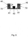
- Figure 9 shows a cross-section of the cargo floor (40) or the fixed floor (72) wherein at least two recesses (41) have been provided. Between the at least two recesses (41) at least one pillar (42) is located, the at least one pillar (42) having been lowered a distance h compared to the adjacent floor (40,72).
- a traverse joist or beam (45) having a substantially U-shaped profile is lowered to its lowest position, the legs of the substantially U-shaped profile will enter said recesses (41) and the bottom of said substantially U-shaped profile will rest upon the pillar (42) and be supported during loading and unloading. In this manner, the entire body or substantially the entire body of the traverse joist or beam (45) can be positioned within the pit formed by said floor (40,72), said recesses (41) and said pillar (42).
- the distance h is so chosen that it will neither create a pit of such depth that it cannot be traversed by e.g. a manually operated pallet lifter nor such that it will push a traverse joist or beam (45) resting on said pillar (42) so far above the average level of the surrounding floor that an insurmountable obstacle to e.g. a manually operated pallet lifter is generated.
- h is smaller than 10 mm, more preferably smaller than 8 mm but most preferably smaller than 5 mm.
- said substantially U-shaped traverse joist or beam (45) is constructed to have a first section (46) so configured that upon lowering the at least one elevation platform (20,20',20",71), the substantially U-shaped traverse joist or beam (45) will guide itself into the recesses (41) and over the pillar (42); and a second section (47) so configured that when the substantially U-shaped traverse joist or beam (45) is in its lowest position and resting atop of the pillar (42), no or only little free space between pillar (42) and said second section of the traverse joist or beam (45) is present, and wherein said first (46) and second (47) sections are so arranged that upon lowering said substantially U-shaped traverse joist or beam (45) over said pillar (42), said first section (46) initially is closest to said
- One example of such a construction could be a substantially U-shaped traverse joist or beam (45) having a first section (46), said first section being funnel shaped with the funnel opening being substantially wider than the width of said pillar (42), and a second section (47), said second section (47) having a width substantially corresponding to the width of said pillar (42) .
- the platform system has been described with reference to hydraulic cylinders as actuators.
- pneumatic or electric actuators such as pneumatic cylinders, electrically driven spindle actuators, winches, such as hydraulic- or electric winches and the like can also be used.
Landscapes
- Engineering & Computer Science (AREA)
- Transportation (AREA)
- Mechanical Engineering (AREA)
- Chemical & Material Sciences (AREA)
- Combustion & Propulsion (AREA)
- Health & Medical Sciences (AREA)
- Public Health (AREA)
- Body Structure For Vehicles (AREA)
Claims (17)
- Plattformsystem (5) zur Verwendung in einem Laderaum eines Lastkraftwagens, Güterwagens oder Anhängers (1), wobei das Plattformsystem Folgendes umfasst:mindestens eine Anhebeplattform (20, 20', 20", 71) mit einem im Wesentlichen rechteckigen Umriss, auf die, bei Verwendung, Güter geladen werden können,wobei die mindestens eine Anhebeplattform (20, 20', 20", 71) durch mehrere horizontal beabstandete und sich vertikal erstreckende Führungen, vorzugsweise vier sich vertikal erstreckende Führungen, geführt wird,wobei jede mindestens eine Anhebeplattform (20, 20', 20", 71) von einem Seilsatz (16rb, 16rf, 16lb, 16lf, 16rb', 16rf', 16lb', 16lf', 16rb', 16rf", 16lb", 16lf", 81), einem Satz von vier Seilen, herabhängt, wobei jedes Seil in dem Seilsatz mit einer der sich vertikal erstreckenden Führungen verbunden ist und ein Ende von jedem der Seile in dem Satz mit mindestens einer Anhebeplattform (20, 20', 20", 71), einer Ecke der mindestens einen Anhebeplattform (20, 20', 20", 71), verbunden ist, dadurch gekennzeichnet, dassdie Seile in einem Satz, deren erste Enden mit ein und derselben Seite einer Anhebeplattform (20, 20', 20", 71) verbunden sind, einen Teilsatz bilden und an einer Position verbunden sind und sich von dieser Position in Richtung des Stellglieds als ein Seil fortsetzen, mindestens ein Stellglied (25, 25', 25", 82), wobei das mindestens eine Stellglied mit der mindestens einen Anhebeplattform (20, 20', 20", 71) verbunden ist, undein zweites Ende eines Seils in dem Seilsatz, das betriebsmäßig mit dem mindestens einen Stellglied (25, 25', 25", 82) verbunden ist.
- Plattformsystem (5) nach Anspruch 1, wobei das Stellglied ein Hydraulikzylinder (25, 25', 25", 82) ist.
- Plattformsystem (5) nach Anspruch 1 oder 2, wobei der Laderaum (12) ein länglicher Raum mit mindestens zwei Anhebeplattformen (20, 20', 20", 72) ist, die der Reihe nach in dem länglichen Raum angeordnet sind.
- Plattformsystem (5) nach einem der Ansprüche 1 bis 3, wobei die Seile (16rb, 16rf, 16lb, 16lf, 16rb', 16rf', 16lb', 16lf' , 16rb' , 16rf", 16lb", 16lf") oder der Seilsatz durch eine Anordnung von Führungsrädern oder -rollen (22, 23, 24) und Seilrollen (29r, 29l) betriebsmäßig mit den Stellgliedern (25, 25', 25") verbunden sind.
- Plattformsystem (5) nach einem der Ansprüche 2 bis 4, wobei die mehreren hydraulischen Stellglieder (25, 25',25") in einem Rahmen (30) angeordnet sind, der an oder in der Nähe von einem der längsverlaufenden Enden (6, 7) des länglichen Laderaums (12) angeordnet ist.
- Plattformsystem (5) nach einem der Ansprüche 1 bis 5, wobei sich die Seile in einem Satz im Wesentlichen vertikal von einer Ecke einer Anhebeplattform (20, 20', 20") zu einem Führungsrad oder einer -rolle (22) an oder in der Nähe von der Oberseite einer sich vertikal erstreckenden Führung erstrecken und sich von dem Führungsrad oder der -rolle (22) horizontal in Richtung des Längsendes (6, 7) des Laderaums (12) erstrecken, wo sich die Stellglieder (25, 25', 25") befinden.
- Plattformsystem (5) nach einem der Ansprüche 1 bis 6, wobei der Rahmen (30) ein im Wesentlichen rechteckiger Rahmen ist, und wobei der Rahmen mit Führungsrädern oder -rollen (23) an oder in der Nähe von zwei seiner Ecken versehen ist, die mit einer Seite des Rahmens verbunden sind, wobei diese Räder oder Rollen (23) die Seile in einer Kurve von ungefähr 90 Grad führen, wobei die Kurve vorzugsweise ein Übergang einer Strecke, wobei sich die Seile entlang der Längserstreckung des Laderaums (12) erstrecken, und einer Strecke, wobei sich die Seile in einem im Wesentlichen rechten Winkel zu der Längserstreckung des Laderaums (12) erstrecken, ist.
- Plattformsystem (5) nach einem der Ansprüche 3 bis 7, wobei die Hydraulikzylinder (25, 25',25") durch den Rahmen (30) derart getragen werden, dass die Längserstreckung der Hydraulikzylinder (25, 25',25") mit der einen gemeinsamen planaren Ebene übereinstimmt, die sich in einem im Wesentlichen rechten Winkel zu der Längserstreckung des Laderaums (12) erstreckt, und wobei der Rahmen mit weiteren Führungsrädern oder - rollen (24) versehen ist, wobei eines der weiteren Führungsräder oder -rollen (24) ein Seil führt, das mit einem Teilsatz in einer im Wesentlichen 90 Grad Biegung in Richtung des äußersten Endes des hydraulischen Stellglieds (25, 25', 25"), das mit dem betreffenden Teilsatz verbunden ist, verbunden ist.
- Plattformsystem (5) nach einem der Ansprüche 3 bis 8, wobei ein Ende des hydraulischen Stellglieds (25, 25', 25") an dem Rahmen (30) befestigt ist und davon getragen wird und das andere freie äußerste Ende des hydraulischen Stellglieds (25, 25', 25") mit zwei Seilrädern (29l, 29r) versehen ist, und wobei das Seil, das mit einem Teilsatz von Seilen verbunden ist, der mit einer Seite einer Anhebeplattform verbunden ist, um das eine der zwei Seilräder geführt wird und das zweite Ende des Seils, das mit einem Teilsatz von Seilen verbunden ist, der mit der anderen Seite derselben Anhebeplattform verbunden ist, um das andere der zwei Seilräder (29l, 29r) geführt wird.
- Plattformsystem (5) nach einem der Ansprüche 6 bis 9, wobei die sich vertikal erstreckenden Führungen mit zwei Führungsrädern (22) an oder in der Nähe von ihrem oberen Ende versehen sind, und wobei einige der sich vertikal erstreckenden Führungen mit Führungsmitteln zum Führen von einem oder mehreren sich horizontal erstreckenden Seilen an oder durch ihren oberen Abschnitt versehen sind.
- Plattformsystem (5) nach einem der Ansprüche 1 bis 3, wobei die mindestens eine Anhebeplattform (71) Teil einer Moduleinheit (70) ist, wobei die Moduleinheit (70) ferner einen fixierten Boden (72) umfasst, und wobei das Stellglied (82) in einem Rahmen (80) angeordnet ist, der einen Teil der Moduleinheit (70) bildet, wobei sich der Rahmen (80) in der Moduleinheit (70) vorzugsweise ganz oben befindet.
- Plattformsystem (5) nach Anspruch 11, wobei die Seile (81) oder der Seilsatz durch eine Anordnung von Führungsrädern oder -rollen (83, 84) und Seilrollen (85) betriebsmäßig mit dem Stellglied (82) verbunden sind.
- Plattformsystem (5) nach einem der Ansprüche 11 bis 12, wobei sich die Seile (81) von einem Seilsatz im Wesentlichen vertikal von den Ecken der Anhebeplattform (71) zu einer Anordnung von Führungsrädern oder -rollen (83, 84) an oder in der Nähe von der Oberseite der sich vertikal erstreckenden Führungen erstrecken und sich von der Anordnung von Führungsrädern oder -rollen (83, 84) horizontal in Richtung der Anordnung von Seilrollen (85) erstrecken, die betriebsmäßig mit dem Stellglied (82) verbunden sind.
- Plattformsystem nach Anspruch 13, wobei das Stellglied (82) parallel zu dem fixierten Boden (72) positioniert ist, wenn innerhalb des Rahmens (80) angeordnet, und wenn sich der Rahmen (80) in der Moduleinheit (70) ganz oben befindet.
- Plattformsystem (5) nach einem der Ansprüche 11 bis 14, wobei der Laderaum (12) in länglicher Raum mit mindestens zwei Moduleinheiten (70) ist, die in dem länglichen Raum der Reihe nach angeordnet sind.
- Ladeboden (40) oder ein fixierter Boden (72) in einem Plattformsystem (5) nach einem der Ansprüche 1 bis 15, der mehrere Ausnehmungen (41) umfasst, die es beliebigen tragenden Querträgern oder -balken (45) ermöglichen, in den Ausnehmungen (41) aufgenommen zu werden, wenn die mindestens eine Anhebeplattform (20, 20', 20", 71) in ihrer tiefsten Position ist, um einen oberflächenbündigen Ladeboden (40) oder fixierten Boden (72) bereitzustellen, und wobei die mindestens zwei Ausnehmungen (41) bereitgestellt wurden und sich zwischen den mindestens zwei Ausnehmungen (41) mindestens eine Säule (42) befindet, wobei die Säule (42) verglichen mit dem angrenzenden Boden (40, 72) um eine Distanz h abgesenkt wurde.
- Im Wesentlichen U-förmiger Querträger oder -balken (45) in dem Aufbau einer Anhebeplattform (20, 20', 20", 71), wobei die Anhebeplattform in einem Plattformsystem (5) nach einem der Ansprüche 1 bis 16 ist, wobei der im Wesentlichen U-förmige Querträger oder -balken (45) einen ersten Abschnitt (46), der so konfiguriert ist, dass sich der im Wesentlichen U-förmige Querträger oder -balken (45) bei Absenken der mindestens einen Anhebeplattform (20, 20', 20", 71) selbst in die Ausnehmungen (41) und über die Säule (42) führt; und einen zweiten Abschnitt (47), der so konfiguriert ist, dass, wenn der im Wesentlichen U-förmige Querträger oder -balken (45) in seiner untersten Position ist und auf der Säule (42) liegt, kein oder nur wenig freier Raum zwischen der Säule (42) und dem zweiten Abschnitt des Querträgers oder -balken (45) vorhanden ist, und wobei der erste (46) und zweite (47) Abschnitt derart angeordnet sind, dass bei Absenken des im Wesentlichen U-förmigen Querträgers oder -balkens (45) über die Säule (42), der erste Abschnitt (46) anfänglich am nächsten an der Säule (42) ist; wobei der erste Abschnitt (46) trichterförmig ist und eine Trichteröffnung aufweist, wobei die Trichteröffnung im Wesentlichen breiter als die Breite der Säule (42) ist, und einen zweiten Abschnitt (47), wobei der zweite Abschnitt (47) eine Breite aufweist, die im Wesentlichen der Breite der Säule (42) entspricht, umfasst.
Applications Claiming Priority (4)
| Application Number | Priority Date | Filing Date | Title |
|---|---|---|---|
| DKPA201200367A DK177551B1 (en) | 2012-05-29 | 2012-05-29 | Platform system for a cargo compartment in a truck or trailer |
| DKPA201200606 | 2012-10-04 | ||
| DKPA201300196 | 2013-04-03 | ||
| PCT/EP2013/060387 WO2013178502A1 (en) | 2012-05-29 | 2013-05-21 | A platform system for a cargo compartment of a truck, lorry or trailer |
Publications (2)
| Publication Number | Publication Date |
|---|---|
| EP2855201A1 EP2855201A1 (de) | 2015-04-08 |
| EP2855201B1 true EP2855201B1 (de) | 2018-04-18 |
Family
ID=48483067
Family Applications (1)
| Application Number | Title | Priority Date | Filing Date |
|---|---|---|---|
| EP13724575.9A Active EP2855201B1 (de) | 2012-05-29 | 2013-05-21 | Plattformsystem für einen laderaum eines lastkraftwagens, güterwagens oder anhängers |
Country Status (3)
| Country | Link |
|---|---|
| US (1) | US9221501B2 (de) |
| EP (1) | EP2855201B1 (de) |
| WO (1) | WO2013178502A1 (de) |
Families Citing this family (9)
| Publication number | Priority date | Publication date | Assignee | Title |
|---|---|---|---|---|
| US9555731B2 (en) * | 2014-02-28 | 2017-01-31 | GM Global Technology Operations LLC | Truck body with rapid load/unload cargo pods |
| US10322874B1 (en) * | 2016-04-13 | 2019-06-18 | Mark D. Curley | Dumpster handling device and method |
| US11117741B2 (en) * | 2016-04-13 | 2021-09-14 | Mark D. Curley | Object handling device and method |
| US10207753B2 (en) * | 2016-08-26 | 2019-02-19 | Aet Logistics, Llc | Trailer for hauling unit load devices |
| ES2684547B1 (es) * | 2017-03-29 | 2019-04-15 | Efitrans Efficient Logistics S L U | Sistema automático de aumento del desplazamiento lineal de una estructura móvil mediante cables |
| US10589969B2 (en) * | 2018-04-25 | 2020-03-17 | Rinaldo Brutoco | System, method and apparatus for widespread commercialization of hydrogen as a carbon-free alternative fuel source |
| CN111071128B (zh) * | 2020-01-06 | 2022-04-19 | 重庆市天友乳业股份有限公司 | 一种畜牧草块运送装置 |
| US11654814B2 (en) * | 2020-02-22 | 2023-05-23 | Strick Trailers, Llc | Truck trailer with deck-level and curb-level unloading capability and additional cubic capacity |
| US11802011B2 (en) * | 2020-05-08 | 2023-10-31 | HomeWorks Restoration Inc. | Transportable side-access cargo container with a controllably deployable second floor |
Family Cites Families (13)
| Publication number | Priority date | Publication date | Assignee | Title |
|---|---|---|---|---|
| CA1234373A (en) * | 1986-02-10 | 1988-03-22 | Atlantis Projects Inc. | Transportation van having load elevating platform located therein |
| JPH041118Y2 (de) * | 1986-07-31 | 1992-01-14 | ||
| NL8700250A (nl) * | 1987-02-02 | 1988-09-01 | W H C Nunnikhoven Holding B V | Voor twee afzonderlijke ladingen geschikt wegtransportvoertuig. |
| DK163041C (da) | 1988-07-19 | 1992-06-09 | Orla Baade | Lad eller container |
| CA2116515C (en) * | 1993-03-05 | 1999-03-30 | Walter P. Demonte | Palletizer trailer and storage container |
| GB9309583D0 (en) * | 1993-05-10 | 1993-06-23 | Aveling Barford Machines Plc | Improvements in and relating to load transport vehicles and containers |
| US5915913A (en) * | 1995-06-07 | 1999-06-29 | Greenlaw; Robert J. | Delivery vehicle with elevator assemblies for multi-tier storage of cargo |
| FR2741034B1 (fr) * | 1995-11-13 | 1998-01-02 | Lohr Ind | Equipement de structure pour vehicule routier procurant un plancher supplementaire mobile |
| US6368034B1 (en) * | 1999-12-22 | 2002-04-09 | Innovative Transportation Service, Inc. | Multi-use trailer for transporting golf carts and the like |
| US6485237B1 (en) * | 2001-05-31 | 2002-11-26 | Richard B. Sandwith | Double-deck trailer |
| CA2534654C (en) * | 2003-07-31 | 2013-01-08 | C. Rasmussen Martin | System and method for moving objects |
| WO2006007522A2 (en) * | 2004-07-01 | 2006-01-19 | Actuant Corporation | In-vehicle lift mechanism |
| US20080067012A1 (en) * | 2006-09-15 | 2008-03-20 | Kobrehel Michael D | Brake Assembly for In-Vehicle Platform Lift |
-
2013
- 2013-05-21 EP EP13724575.9A patent/EP2855201B1/de active Active
- 2013-05-21 US US14/404,882 patent/US9221501B2/en active Active
- 2013-05-21 WO PCT/EP2013/060387 patent/WO2013178502A1/en not_active Ceased
Non-Patent Citations (1)
| Title |
|---|
| None * |
Also Published As
| Publication number | Publication date |
|---|---|
| EP2855201A1 (de) | 2015-04-08 |
| US9221501B2 (en) | 2015-12-29 |
| WO2013178502A1 (en) | 2013-12-05 |
| US20150232134A1 (en) | 2015-08-20 |
Similar Documents
| Publication | Publication Date | Title |
|---|---|---|
| EP2855201B1 (de) | Plattformsystem für einen laderaum eines lastkraftwagens, güterwagens oder anhängers | |
| EP1259398B1 (de) | Vorrichtung zum heben, handhaben und transportieren eines containers | |
| EP1592579B1 (de) | Kraftfahrzeuge und fahrzeuganhänger mit beweglichen plattformen | |
| EP3016863B1 (de) | Mehrstöckiger frachtbehälter | |
| US10752151B2 (en) | Transport platform | |
| CN107406239B (zh) | 用于iso集装箱的跨车装置 | |
| RU2141905C1 (ru) | Автомобиль с кузовом | |
| CA2700202C (en) | Method and apparatus for stacking loads in vehicles | |
| WO1990000990A1 (en) | Cargo space or container | |
| CN1874942A (zh) | 物料搬运系统 | |
| US20030147734A1 (en) | Goods handling system | |
| EP0564557B1 (de) | Fahrzeug, und verfahren zum laden und entladen solchen fahrzeugs | |
| CN105722724B (zh) | 用于装卸集装箱的车辆、设施以及站 | |
| CN107804207B (zh) | 一种液压装卸道路运输车 | |
| DK177551B1 (en) | Platform system for a cargo compartment in a truck or trailer | |
| JP7707030B2 (ja) | 格納装置 | |
| RU2743864C1 (ru) | Способ установки сменного кузова | |
| US20170036893A1 (en) | Apparatus for moving a shipping container | |
| EP2774812B1 (de) | Verfahren zur Herstellung eines Betonelements | |
| CN112455313B (zh) | 一种牵引运输车及物料运输系统 | |
| GB1580706A (en) | Vehicle load carrying containers | |
| JP2578010Y2 (ja) | 移送装置を具えたエレベータ式駐車装置 | |
| EP1498308A1 (de) | Warenhandhabungssystem | |
| KR20150081880A (ko) | 선실이 이동가능하게 설치된 컨테이너선 | |
| JP2023121711A (ja) | フォークリフト、荷役システム、積載方法、及びフォークリフトの制御装置 |
Legal Events
| Date | Code | Title | Description |
|---|---|---|---|
| PUAI | Public reference made under article 153(3) epc to a published international application that has entered the european phase |
Free format text: ORIGINAL CODE: 0009012 |
|
| 17P | Request for examination filed |
Effective date: 20150105 |
|
| AK | Designated contracting states |
Kind code of ref document: A1 Designated state(s): AL AT BE BG CH CY CZ DE DK EE ES FI FR GB GR HR HU IE IS IT LI LT LU LV MC MK MT NL NO PL PT RO RS SE SI SK SM TR |
|
| AX | Request for extension of the european patent |
Extension state: BA ME |
|
| DAX | Request for extension of the european patent (deleted) | ||
| GRAP | Despatch of communication of intention to grant a patent |
Free format text: ORIGINAL CODE: EPIDOSNIGR1 |
|
| INTG | Intention to grant announced |
Effective date: 20160916 |
|
| GRAJ | Information related to disapproval of communication of intention to grant by the applicant or resumption of examination proceedings by the epo deleted |
Free format text: ORIGINAL CODE: EPIDOSDIGR1 |
|
| INTC | Intention to grant announced (deleted) | ||
| GRAP | Despatch of communication of intention to grant a patent |
Free format text: ORIGINAL CODE: EPIDOSNIGR1 |
|
| INTG | Intention to grant announced |
Effective date: 20171109 |
|
| GRAS | Grant fee paid |
Free format text: ORIGINAL CODE: EPIDOSNIGR3 |
|
| GRAA | (expected) grant |
Free format text: ORIGINAL CODE: 0009210 |
|
| AK | Designated contracting states |
Kind code of ref document: B1 Designated state(s): AL AT BE BG CH CY CZ DE DK EE ES FI FR GB GR HR HU IE IS IT LI LT LU LV MC MK MT NL NO PL PT RO RS SE SI SK SM TR |
|
| REG | Reference to a national code |
Ref country code: GB Ref legal event code: FG4D |
|
| REG | Reference to a national code |
Ref country code: CH Ref legal event code: EP |
|
| REG | Reference to a national code |
Ref country code: AT Ref legal event code: REF Ref document number: 990069 Country of ref document: AT Kind code of ref document: T Effective date: 20180515 |
|
| REG | Reference to a national code |
Ref country code: IE Ref legal event code: FG4D |
|
| REG | Reference to a national code |
Ref country code: DE Ref legal event code: R096 Ref document number: 602013036064 Country of ref document: DE |
|
| REG | Reference to a national code |
Ref country code: FR Ref legal event code: PLFP Year of fee payment: 6 |
|
| REG | Reference to a national code |
Ref country code: NL Ref legal event code: FP |
|
| REG | Reference to a national code |
Ref country code: LT Ref legal event code: MG4D |
|
| PG25 | Lapsed in a contracting state [announced via postgrant information from national office to epo] |
Ref country code: FI Free format text: LAPSE BECAUSE OF FAILURE TO SUBMIT A TRANSLATION OF THE DESCRIPTION OR TO PAY THE FEE WITHIN THE PRESCRIBED TIME-LIMIT Effective date: 20180418 Ref country code: NO Free format text: LAPSE BECAUSE OF FAILURE TO SUBMIT A TRANSLATION OF THE DESCRIPTION OR TO PAY THE FEE WITHIN THE PRESCRIBED TIME-LIMIT Effective date: 20180718 Ref country code: BG Free format text: LAPSE BECAUSE OF FAILURE TO SUBMIT A TRANSLATION OF THE DESCRIPTION OR TO PAY THE FEE WITHIN THE PRESCRIBED TIME-LIMIT Effective date: 20180718 Ref country code: AL Free format text: LAPSE BECAUSE OF FAILURE TO SUBMIT A TRANSLATION OF THE DESCRIPTION OR TO PAY THE FEE WITHIN THE PRESCRIBED TIME-LIMIT Effective date: 20180418 Ref country code: ES Free format text: LAPSE BECAUSE OF FAILURE TO SUBMIT A TRANSLATION OF THE DESCRIPTION OR TO PAY THE FEE WITHIN THE PRESCRIBED TIME-LIMIT Effective date: 20180418 Ref country code: SE Free format text: LAPSE BECAUSE OF FAILURE TO SUBMIT A TRANSLATION OF THE DESCRIPTION OR TO PAY THE FEE WITHIN THE PRESCRIBED TIME-LIMIT Effective date: 20180418 Ref country code: PL Free format text: LAPSE BECAUSE OF FAILURE TO SUBMIT A TRANSLATION OF THE DESCRIPTION OR TO PAY THE FEE WITHIN THE PRESCRIBED TIME-LIMIT Effective date: 20180418 Ref country code: LT Free format text: LAPSE BECAUSE OF FAILURE TO SUBMIT A TRANSLATION OF THE DESCRIPTION OR TO PAY THE FEE WITHIN THE PRESCRIBED TIME-LIMIT Effective date: 20180418 |
|
| PG25 | Lapsed in a contracting state [announced via postgrant information from national office to epo] |
Ref country code: LV Free format text: LAPSE BECAUSE OF FAILURE TO SUBMIT A TRANSLATION OF THE DESCRIPTION OR TO PAY THE FEE WITHIN THE PRESCRIBED TIME-LIMIT Effective date: 20180418 Ref country code: HR Free format text: LAPSE BECAUSE OF FAILURE TO SUBMIT A TRANSLATION OF THE DESCRIPTION OR TO PAY THE FEE WITHIN THE PRESCRIBED TIME-LIMIT Effective date: 20180418 Ref country code: GR Free format text: LAPSE BECAUSE OF FAILURE TO SUBMIT A TRANSLATION OF THE DESCRIPTION OR TO PAY THE FEE WITHIN THE PRESCRIBED TIME-LIMIT Effective date: 20180719 Ref country code: RS Free format text: LAPSE BECAUSE OF FAILURE TO SUBMIT A TRANSLATION OF THE DESCRIPTION OR TO PAY THE FEE WITHIN THE PRESCRIBED TIME-LIMIT Effective date: 20180418 |
|
| REG | Reference to a national code |
Ref country code: CH Ref legal event code: PL |
|
| REG | Reference to a national code |
Ref country code: AT Ref legal event code: MK05 Ref document number: 990069 Country of ref document: AT Kind code of ref document: T Effective date: 20180418 |
|
| PG25 | Lapsed in a contracting state [announced via postgrant information from national office to epo] |
Ref country code: PT Free format text: LAPSE BECAUSE OF FAILURE TO SUBMIT A TRANSLATION OF THE DESCRIPTION OR TO PAY THE FEE WITHIN THE PRESCRIBED TIME-LIMIT Effective date: 20180820 |
|
| REG | Reference to a national code |
Ref country code: DE Ref legal event code: R097 Ref document number: 602013036064 Country of ref document: DE |
|
| PG25 | Lapsed in a contracting state [announced via postgrant information from national office to epo] |
Ref country code: DK Free format text: LAPSE BECAUSE OF FAILURE TO SUBMIT A TRANSLATION OF THE DESCRIPTION OR TO PAY THE FEE WITHIN THE PRESCRIBED TIME-LIMIT Effective date: 20180418 Ref country code: EE Free format text: LAPSE BECAUSE OF FAILURE TO SUBMIT A TRANSLATION OF THE DESCRIPTION OR TO PAY THE FEE WITHIN THE PRESCRIBED TIME-LIMIT Effective date: 20180418 Ref country code: AT Free format text: LAPSE BECAUSE OF FAILURE TO SUBMIT A TRANSLATION OF THE DESCRIPTION OR TO PAY THE FEE WITHIN THE PRESCRIBED TIME-LIMIT Effective date: 20180418 Ref country code: RO Free format text: LAPSE BECAUSE OF FAILURE TO SUBMIT A TRANSLATION OF THE DESCRIPTION OR TO PAY THE FEE WITHIN THE PRESCRIBED TIME-LIMIT Effective date: 20180418 Ref country code: CZ Free format text: LAPSE BECAUSE OF FAILURE TO SUBMIT A TRANSLATION OF THE DESCRIPTION OR TO PAY THE FEE WITHIN THE PRESCRIBED TIME-LIMIT Effective date: 20180418 Ref country code: MC Free format text: LAPSE BECAUSE OF FAILURE TO SUBMIT A TRANSLATION OF THE DESCRIPTION OR TO PAY THE FEE WITHIN THE PRESCRIBED TIME-LIMIT Effective date: 20180418 Ref country code: SK Free format text: LAPSE BECAUSE OF FAILURE TO SUBMIT A TRANSLATION OF THE DESCRIPTION OR TO PAY THE FEE WITHIN THE PRESCRIBED TIME-LIMIT Effective date: 20180418 |
|
| REG | Reference to a national code |
Ref country code: IE Ref legal event code: MM4A |
|
| PLBE | No opposition filed within time limit |
Free format text: ORIGINAL CODE: 0009261 |
|
| STAA | Information on the status of an ep patent application or granted ep patent |
Free format text: STATUS: NO OPPOSITION FILED WITHIN TIME LIMIT |
|
| PG25 | Lapsed in a contracting state [announced via postgrant information from national office to epo] |
Ref country code: IT Free format text: LAPSE BECAUSE OF FAILURE TO SUBMIT A TRANSLATION OF THE DESCRIPTION OR TO PAY THE FEE WITHIN THE PRESCRIBED TIME-LIMIT Effective date: 20180418 Ref country code: SM Free format text: LAPSE BECAUSE OF FAILURE TO SUBMIT A TRANSLATION OF THE DESCRIPTION OR TO PAY THE FEE WITHIN THE PRESCRIBED TIME-LIMIT Effective date: 20180418 Ref country code: CH Free format text: LAPSE BECAUSE OF NON-PAYMENT OF DUE FEES Effective date: 20180531 Ref country code: LI Free format text: LAPSE BECAUSE OF NON-PAYMENT OF DUE FEES Effective date: 20180531 |
|
| 26N | No opposition filed |
Effective date: 20190121 |
|
| PG25 | Lapsed in a contracting state [announced via postgrant information from national office to epo] |
Ref country code: LU Free format text: LAPSE BECAUSE OF NON-PAYMENT OF DUE FEES Effective date: 20180521 |
|
| PG25 | Lapsed in a contracting state [announced via postgrant information from national office to epo] |
Ref country code: IE Free format text: LAPSE BECAUSE OF NON-PAYMENT OF DUE FEES Effective date: 20180521 |
|
| PG25 | Lapsed in a contracting state [announced via postgrant information from national office to epo] |
Ref country code: SI Free format text: LAPSE BECAUSE OF FAILURE TO SUBMIT A TRANSLATION OF THE DESCRIPTION OR TO PAY THE FEE WITHIN THE PRESCRIBED TIME-LIMIT Effective date: 20180418 |
|
| PG25 | Lapsed in a contracting state [announced via postgrant information from national office to epo] |
Ref country code: MT Free format text: LAPSE BECAUSE OF NON-PAYMENT OF DUE FEES Effective date: 20180521 |
|
| PG25 | Lapsed in a contracting state [announced via postgrant information from national office to epo] |
Ref country code: TR Free format text: LAPSE BECAUSE OF FAILURE TO SUBMIT A TRANSLATION OF THE DESCRIPTION OR TO PAY THE FEE WITHIN THE PRESCRIBED TIME-LIMIT Effective date: 20180418 |
|
| PG25 | Lapsed in a contracting state [announced via postgrant information from national office to epo] |
Ref country code: MK Free format text: LAPSE BECAUSE OF NON-PAYMENT OF DUE FEES Effective date: 20180418 Ref country code: HU Free format text: LAPSE BECAUSE OF FAILURE TO SUBMIT A TRANSLATION OF THE DESCRIPTION OR TO PAY THE FEE WITHIN THE PRESCRIBED TIME-LIMIT; INVALID AB INITIO Effective date: 20130521 Ref country code: CY Free format text: LAPSE BECAUSE OF FAILURE TO SUBMIT A TRANSLATION OF THE DESCRIPTION OR TO PAY THE FEE WITHIN THE PRESCRIBED TIME-LIMIT Effective date: 20180418 |
|
| PG25 | Lapsed in a contracting state [announced via postgrant information from national office to epo] |
Ref country code: IS Free format text: LAPSE BECAUSE OF FAILURE TO SUBMIT A TRANSLATION OF THE DESCRIPTION OR TO PAY THE FEE WITHIN THE PRESCRIBED TIME-LIMIT Effective date: 20180818 |
|
| PGFP | Annual fee paid to national office [announced via postgrant information from national office to epo] |
Ref country code: NL Payment date: 20250514 Year of fee payment: 13 |
|
| PGFP | Annual fee paid to national office [announced via postgrant information from national office to epo] |
Ref country code: DE Payment date: 20250514 Year of fee payment: 13 |
|
| PGFP | Annual fee paid to national office [announced via postgrant information from national office to epo] |
Ref country code: GB Payment date: 20250512 Year of fee payment: 13 |
|
| PGFP | Annual fee paid to national office [announced via postgrant information from national office to epo] |
Ref country code: BE Payment date: 20250514 Year of fee payment: 13 |
|
| PGFP | Annual fee paid to national office [announced via postgrant information from national office to epo] |
Ref country code: FR Payment date: 20250512 Year of fee payment: 13 |