EP2855251B1 - Verbesserungen an der aufhängungsgeometrie von mehrrumpfschiffen - Google Patents
Verbesserungen an der aufhängungsgeometrie von mehrrumpfschiffen Download PDFInfo
- Publication number
- EP2855251B1 EP2855251B1 EP13799908.2A EP13799908A EP2855251B1 EP 2855251 B1 EP2855251 B1 EP 2855251B1 EP 13799908 A EP13799908 A EP 13799908A EP 2855251 B1 EP2855251 B1 EP 2855251B1
- Authority
- EP
- European Patent Office
- Prior art keywords
- hull
- locating
- linkage
- sliding
- support
- Prior art date
- Legal status (The legal status is an assumption and is not a legal conclusion. Google has not performed a legal analysis and makes no representation as to the accuracy of the status listed.)
- Active
Links
Images


Classifications
-
- B—PERFORMING OPERATIONS; TRANSPORTING
- B63—SHIPS OR OTHER WATERBORNE VESSELS; RELATED EQUIPMENT
- B63B—SHIPS OR OTHER WATERBORNE VESSELS; EQUIPMENT FOR SHIPPING
- B63B1/00—Hydrodynamic or hydrostatic features of hulls or of hydrofoils
- B63B1/02—Hydrodynamic or hydrostatic features of hulls or of hydrofoils deriving lift mainly from water displacement
- B63B1/10—Hydrodynamic or hydrostatic features of hulls or of hydrofoils deriving lift mainly from water displacement with multiple hulls
- B63B1/12—Hydrodynamic or hydrostatic features of hulls or of hydrofoils deriving lift mainly from water displacement with multiple hulls the hulls being interconnected rigidly
- B63B1/121—Hydrodynamic or hydrostatic features of hulls or of hydrofoils deriving lift mainly from water displacement with multiple hulls the hulls being interconnected rigidly comprising two hulls
-
- B—PERFORMING OPERATIONS; TRANSPORTING
- B63—SHIPS OR OTHER WATERBORNE VESSELS; RELATED EQUIPMENT
- B63B—SHIPS OR OTHER WATERBORNE VESSELS; EQUIPMENT FOR SHIPPING
- B63B1/00—Hydrodynamic or hydrostatic features of hulls or of hydrofoils
- B63B1/02—Hydrodynamic or hydrostatic features of hulls or of hydrofoils deriving lift mainly from water displacement
- B63B1/10—Hydrodynamic or hydrostatic features of hulls or of hydrofoils deriving lift mainly from water displacement with multiple hulls
- B63B1/14—Hydrodynamic or hydrostatic features of hulls or of hydrofoils deriving lift mainly from water displacement with multiple hulls the hulls being interconnected resiliently or having means for actively varying hull shape or configuration
-
- B—PERFORMING OPERATIONS; TRANSPORTING
- B63—SHIPS OR OTHER WATERBORNE VESSELS; RELATED EQUIPMENT
- B63B—SHIPS OR OTHER WATERBORNE VESSELS; EQUIPMENT FOR SHIPPING
- B63B17/00—Vessels parts, details, or accessories, not otherwise provided for
-
- B—PERFORMING OPERATIONS; TRANSPORTING
- B63—SHIPS OR OTHER WATERBORNE VESSELS; RELATED EQUIPMENT
- B63B—SHIPS OR OTHER WATERBORNE VESSELS; EQUIPMENT FOR SHIPPING
- B63B27/00—Arrangement of ship-based loading or unloading equipment for cargo or passengers
- B63B27/14—Arrangement of ship-based loading or unloading equipment for cargo or passengers of ramps, gangways or outboard ladders ; Pilot lifts
-
- B—PERFORMING OPERATIONS; TRANSPORTING
- B63—SHIPS OR OTHER WATERBORNE VESSELS; RELATED EQUIPMENT
- B63B—SHIPS OR OTHER WATERBORNE VESSELS; EQUIPMENT FOR SHIPPING
- B63B27/00—Arrangement of ship-based loading or unloading equipment for cargo or passengers
- B63B27/30—Arrangement of ship-based loading or unloading equipment for transfer at sea between ships or between ships and off-shore structures
-
- B—PERFORMING OPERATIONS; TRANSPORTING
- B63—SHIPS OR OTHER WATERBORNE VESSELS; RELATED EQUIPMENT
- B63B—SHIPS OR OTHER WATERBORNE VESSELS; EQUIPMENT FOR SHIPPING
- B63B39/00—Equipment to decrease pitch, roll, or like unwanted vessel movements; Apparatus for indicating vessel attitude
-
- B—PERFORMING OPERATIONS; TRANSPORTING
- B63—SHIPS OR OTHER WATERBORNE VESSELS; RELATED EQUIPMENT
- B63B—SHIPS OR OTHER WATERBORNE VESSELS; EQUIPMENT FOR SHIPPING
- B63B39/00—Equipment to decrease pitch, roll, or like unwanted vessel movements; Apparatus for indicating vessel attitude
- B63B39/04—Equipment to decrease pitch, roll, or like unwanted vessel movements; Apparatus for indicating vessel attitude to decrease vessel movements by using gyroscopes directly
-
- B—PERFORMING OPERATIONS; TRANSPORTING
- B63—SHIPS OR OTHER WATERBORNE VESSELS; RELATED EQUIPMENT
- B63B—SHIPS OR OTHER WATERBORNE VESSELS; EQUIPMENT FOR SHIPPING
- B63B1/00—Hydrodynamic or hydrostatic features of hulls or of hydrofoils
- B63B1/02—Hydrodynamic or hydrostatic features of hulls or of hydrofoils deriving lift mainly from water displacement
- B63B1/10—Hydrodynamic or hydrostatic features of hulls or of hydrofoils deriving lift mainly from water displacement with multiple hulls
- B63B1/12—Hydrodynamic or hydrostatic features of hulls or of hydrofoils deriving lift mainly from water displacement with multiple hulls the hulls being interconnected rigidly
- B63B1/121—Hydrodynamic or hydrostatic features of hulls or of hydrofoils deriving lift mainly from water displacement with multiple hulls the hulls being interconnected rigidly comprising two hulls
- B63B2001/123—Hydrodynamic or hydrostatic features of hulls or of hydrofoils deriving lift mainly from water displacement with multiple hulls the hulls being interconnected rigidly comprising two hulls interconnected by a plurality of beams, or the like members only
-
- B—PERFORMING OPERATIONS; TRANSPORTING
- B63—SHIPS OR OTHER WATERBORNE VESSELS; RELATED EQUIPMENT
- B63B—SHIPS OR OTHER WATERBORNE VESSELS; EQUIPMENT FOR SHIPPING
- B63B1/00—Hydrodynamic or hydrostatic features of hulls or of hydrofoils
- B63B1/02—Hydrodynamic or hydrostatic features of hulls or of hydrofoils deriving lift mainly from water displacement
- B63B1/10—Hydrodynamic or hydrostatic features of hulls or of hydrofoils deriving lift mainly from water displacement with multiple hulls
- B63B1/14—Hydrodynamic or hydrostatic features of hulls or of hydrofoils deriving lift mainly from water displacement with multiple hulls the hulls being interconnected resiliently or having means for actively varying hull shape or configuration
- B63B2001/145—Hydrodynamic or hydrostatic features of hulls or of hydrofoils deriving lift mainly from water displacement with multiple hulls the hulls being interconnected resiliently or having means for actively varying hull shape or configuration having means for actively varying hull shape or configuration
-
- B—PERFORMING OPERATIONS; TRANSPORTING
- B63—SHIPS OR OTHER WATERBORNE VESSELS; RELATED EQUIPMENT
- B63B—SHIPS OR OTHER WATERBORNE VESSELS; EQUIPMENT FOR SHIPPING
- B63B17/00—Vessels parts, details, or accessories, not otherwise provided for
- B63B2017/0072—Seaway compensators
Definitions
- the present invention is generally directed to water craft and in particular to methods of or systems/arrangements for at least partially suspending or supporting a body above at least two movable hulls.
- the support forces are provided by rams which provide a moment on the trailing arms which can require the trailing arms to be of very high strength and large section on some vessels and places a high side load on the sliding joints of the variable length arm which increases the friction of the sliding joints and therefore reduces joint life and ride comfort.
- the rams are provided connected directly between the body and the hull, which can require a large tower on the deck of the body to accommodate the rams which can be difficult to package in some vessel designs and layouts.
- suspension arms and rams are located in separate areas of the vessel, having separate load paths through respective mounting points into the body and/or the hull(s), the greater the spacing between the respective mounting points, generally the more bending induced into the body and/or hull and the less efficient the design in terms of packaging and weight.
- a similar locating arrangement is also disclosed in document US 3326166 .
- a hull locating arrangement for a multi-hulled vessel having a body at least partially suspended above at least a first and a second hull by support components, the hull locating least a first and a second hull, the hull locating arrangement comprising for a said hull a first loc ating linkage and a second locating linkage to together constrain said hull in the lateral, longitudinal, roll and yaw directions relative to the body, the first and second locating linkages being longitudinally spaced from each other.
- the first locating linkage includes a first part and a second part, one of said parts of the first locating linkage being pivotally connected to the body about a body end pivot axis, the other of said parts being pivotally connected to said hull about a hull end pivot axis.
- the first locating linkage being arranged to permit relative motion between the first and second parts along at least one sliding axis to thereby permit the first locating linkage to vary in length between the body end pivot axis and the hull end pivot axis whilst providing at least a lateral constraint of the said hull relative to the body.
- the support components including a first support component adjacent the first locating linkage, the first support component including a first support element providing a support force supporting a portion of the body above the said hull, wherein the support force of the first support element of the first support component has a line of action that is within thirty degrees of parallel to a first linkage plane extending through the body end pivot axis and the hull end pivot axis.
- the locating forces from the first locating linkage are applied to the body and the said hull at the body end pivot axis and hull end pivot axis.
- the first support element force is applied to the body or the said hull at at least one of the body end pivot axis and hull end pivot axis.
- the support force of the first support element may have a line of action that is aligned with or at a tighter angle of for example 5, 10 or 20 degrees of parallel to the first linkage plane.
- the line of action of the support force of the first support element may be offset from the body end pivot axis or the hull end pivot axis or the first linkage plane by a distance of less than ten percent of a length of the first hull, for example 2, 5 or 10 percent of the (waterline) length.
- the at least one sliding axis of the first locating linkage may include at least two laterally spaced sliding axes defining a first sliding plane and the line of action of the support force of the first support element may be substantially aligned with said first sliding plane.
- the line of action of the support force of the first support element may be substantially aligned with both the first linkage plane (and the first sliding plane) to thereby minimise bending moments and side loads in the first locating linkage resulting from the support force.
- the first locating linkage may include bearings or bushings to permit the relative motion between the first and second parts along said at least one sliding axis.
- the hull end pivot axis and the body end pivot axis of the first locating linkage of said hulls may be aligned substantially laterally with respect to the body of the vessel.
- the first support component may further include a second support element.
- the first and/or second support element may be connected between the first part and the second part.
- the at least one sliding axis may be a single sliding axis.
- the at least one sliding axis may be a pair of parallel first and second laterally spaced sliding axes.
- Bearings or bushings may be provided between the first part and the second part and may be arranged to effectively constrain the relative motion between the first and second parts to a linear sliding motion along said first and second laterally spaced sliding axes, said sliding axes being parallel to each other and substantially perpendicular to the body and hull end pivot axes.
- the first linkage plane of the first locating linkage may be substantially perpendicular to the body of the vessel during operation. However due to practical limits on the lengths of arms and other geometry considerations, the first linkage plane of the first locating linkage may only be substantially perpendicular to the main body during a part of the total range of operation of the first locating linkage. So alternatively the first linkage plane of the first locating linkage may be within 5, 10, 20, 30 or even 40 degrees of perpendicular to the body of the vessel during operation.
- the second locating linkage may constrain the longitudinal motion of the hull relative to the body.
- the support components may further include second support components for providing support forces in the second locating linkage between said hull and the body.
- the support force of the first support means acts (or has a line of action that is) substantially parallel to the at least one sliding axis of the first locating linkage.
- the support force of the first support means may act in a direction (or have a line of action) that is substantially aligned with either the at least one sliding axis of the first locating linkage or a plane defined at least in part by the at least one sliding axis of the first locating linkage.
- the variable length of the first locating linkage may vary within a range defined as a first locating linkage stroke distance.
- the first support component may be arranged such that the resultant force has a line of action substantially aligned with the first sliding axis or passing within a distance from the first and second pivot axes of the first locating linkage that is less than twenty-five percent of said stroke distance.
- the first support component may be connected between the first part and the second part.
- One or more forms of the present invention may provide a multi-hulled vessel including a main body and at least one left hull and at least one right hull, each of said at least one left hull and at least one right hull being moveable with respect to the main body. At least one hull of said at least one left hull and at least one right hull is located relative to the main body by a hull locating arrangement according to the first aspect of the invention.
- the hull locating arrangement is arranged to constrain the hull relative to the main body in the lateral, longitudinal, roll and yaw directions, but to permit motion of the hull in the heave and pitch directions.
- the hull locating arrangement includes longitudinally spaced first and second locating linkages.
- the first locating linkage is a variable length arm between the main body and the hull
- the second locating linkage is a fixed length arm between the main body and the hull.
- a first end of the respective first and second locating linkages is rotatably connected to the main body by a respective first joint having a first pivot axis
- a second end of the respective first and second locating linkages is rotatably connected to the hull by a respective second joint having a second pivot axis.
- the first locating linkage may vary in length along a first sliding axis and the variable length of the first locating linkage may vary within a range defined as a first locating linkage stroke distance.
- first locating linkage may further include support means providing a support force to support a portion of the main body above the hull.
- the first locating linkage may further include support means providing a support force to support a portion of the main body above the hull, the support force having a line of action substantially aligned with the first sliding axis or passing within a distance from the first and second pivot axes of the first locating linkage that is less than twenty-five percent of said stroke distance (and is preferably substantially parallel to the first sliding axis).
- the first locating linkage may include a first part connected to the first joint and a second part connected to the second joint, the first and second parts sliding relative to each other along the first sliding axis.
- the support means may be connected between the first part and the second part.
- the support means may include multiple devices.
- the resultant force of said multiple devices may have a line of action substantially aligned with the first sliding axis or passing within a distance from the first and second pivot axes of the first locating linkage that is less than twenty-five percent of said stroke distance.
- the first sliding axis may be within 40 degrees of vertical relative to the main body during operation. From a force standpoint, ideally the first sliding axis is substantial vertical with respect to the main body to minimise the longitudinal component of the support force input from the first locating linkage into the main body. However the geometry of the second locating linkage can require the first sliding axis to deviate from vertical. Also from a packaging standpoint it can be preferable to angle the first sliding axis from vertical to reduce the requirement for the first locating linkage to penetrate the hull or a deck area of the vessel.
- FIG. 1 there is shown a catamaran 1 with a main body 2 suspended above the independently moveable hulls 3. The gunnels on the near side are omitted to fully expose the cabin 4 and the hull locating arrangement for the visible hull.
- the hull locating arrangement comprises a back hull locating linkage 6 and a front hull locating linkage 7.
- the front locating linkage shown includes a leading arm 8 rotatably connected to the body 2 by pivot 9 such as bearings or bushings and rotatably connected to the hull 3 by pivot 10.
- This provides lateral, longitudinal and roll constraints to the motion of the hull relative to the body.
- the use of a second lateral constraint at a longitudinally spaced position i.e. the back locating linkage
- a front support means 11 (such as a spring damper unit or one or more hydraulic cylinders) is provided, packaged inside a suspension tower 12 which can be located in the gunnels or in the cabin structure for example.
- the front support means is connected to the body by pivot 13 and to the leading arm by pivot 14.
- the distance of the connection point 14 of the front support cylinder 11 along the leading arm determines a mechanical advantage on the support cylinder and can be used for many beneficial reasons such as to reduce the total length of the cylinder (or other support means) to reduce the height of the suspension tower 12 and to improve the ratio of buckling strength versus weight of the cylinder 11.
- FIG. 2 shows the back hull locating linkage 6 in more detail with the body omitted for clarity.
- the back hull locating linkage is shown substantially vertical with respect to the body at ride height, the linkage can be inclined to suit the packaging of the vessel, however this increases any longitudinal component of the rear support force acting on both the body and the hull and resolved through the leading arm.
- This rear locating linkage 6 is variable in length between the body pivot 21 and the hull pivot 22 and as shown in Figure 2 includes a sliding frame made up of two laterally spaced sliding members 24 and 25.
- the sliding members are shown as cylindrical devices, but as the upper and lower pivots 21 and 22 reduce or remove the bending moment about laterally extending axes (such as the pivot axes of the pivots) the sliding members can be wider in section in a lateral direction than in a longitudinal direction.
- Each sliding member has two parts, one of which slides inside the other telescopically.
- the outer part 26 is shown connected to the body and the inner part connected to the hull although the frame can be used inverted so that the inner part 27 is connected to the body.
- bushings or bearings are used in pairs between the inner and outer parts of the sliding frame. For ease of maintenance these can be split shell bushes in the outer parts, although using a bush or bearing in the opposite end of each part from the pivots improves bearing spacing which can be beneficial.
- one or more support means is used to provide support to the vessel body.
- the back support means is two hydraulic cylinders 28 and 29 which are connected either directly between the body and the hull or indirectly by being connected between the inner and outer parts of the sliding frame.
- the support means may comprise a supporting spring and a damper such as a hydraulic or pneumatic support cylinder and a shock absorber, or part of an interconnected suspension system such as those shown in the applicant's previously mentioned International patent applications, details of which are incorporated herein by reference.
- the stroke of the suspension system (the vertical travel of the hull relative to the body) together with the lack of mechanical advantage (or lever ratio) of the back hull locating linkage 6 and back support cylinders 28 and 29 can require the top of the linkage to be housed above the deck of the body, such as in a suspension tower 30 which is preferably tied or integrated into the gunnels or the cabin or other superstructure as shown in Figure 1 .
- a suspension tower 30 which is preferably tied or integrated into the gunnels or the cabin or other superstructure as shown in Figure 1 .
- the lower ends of the sliding frame and support means can be recessed into wells 34 or cut-outs in the hulls as shown in Figure 2 .
- Such a well can be sealed from the buoyant volume of the hull and to prevent water from collecting in the well 34 a vent 35 or other means of drainage can be provided as shown.
- the support means such as cylinders 28 and 29 can be located in one or more of the sliding members 24 and 25, in which case it is possible to use a single sliding member which penetrates the hull and is sealed by a flexible membrane between the sliding member and the hull.
- a large stroke of the variable length arm arrangement with no mechanical advantage as shown in the rear linkage can require the support cylinders to be larger than hydraulically necessary to avoid the mechanical risk of buckling. This is particularly necessary when the cylinders are free to rotate at both ends, so a more efficient solution is to fix the ends of the cylinders to the outer and inner parts of the sliding frame. In this case alignment is especially important, so preferably the force of each support cylinder 28, 29 is aligned with a plane defined by the sliding axes of the laterally spaced sliding members 24, 25 as shown in Figure 2 .
- the outer parts 26 of sliding members 24 and 25 are laterally connected by a beam 41 as shown in Figure 3 and the inner parts 27 are connected by a beam 42 to improve the rigidity of the sliding frame and reduce variations in alignment of the inner and outer parts.
- the operation and life of the sliding frame can be improved by minimising such misalignment and by minimising the side load on the bearings between the inner and outer parts through keeping the line of action of the total force from the support means as close to the pivot axes of the sliding frame as possible.
- the support cylinders can be positioned on either side of the plane defined by the axes of the two sliding members as shown in Figure 3 .
- the support cylinders of the arrangement shown in Figure 3 can be rigidly fixed between the inner and outer parts of the sliding frame even when the support cylinders are not in line with the sliding members, as long as the axes of both cylinders and both sliding members are parallel.
- Figures 4 to 7 show the range of displacements possible between the hulls and the body.
- the suspension is fully compressed in Figure 4 and fully extended in Figure 5 .
- Figure 6 the suspension is in a full pitch in the hull nose up direction and similarly in Figure 7 hull nose down full pitch travel is shown.
- a warp mode (not shown) is possible.
- the inner 27 and outer 26 parts of the laterally spaced sliding members 24 and 25 are not concentric.
- a lower-mid beam 43 braces between the lower ends of the outer parts 26 and locates bushings 46 around the inner parts 27.
- an upper-mid beam 44 braces between the upper ends of the inner parts 27 and locates bushings 45 around the outer parts 26.
- the upper (or outer) frame comprises the outer parts 26, the lower-mid beam 43 and the upper beam 41 between the tops of the outer members.
- the lower (or inner) frame comprises the inner parts 27, the upper-mid beam 44 and the lower beam 42 between the bottoms of the inner members.
- the support rams 28 and 29 can be mounted directly between the upper beam 41 and the lower beam 42 in any arrangement desired such as the longitudinal spacing shown in Figure 3 or the lateral spacing shown in Figure 8 .
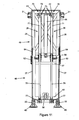
- Figures 9 to 11 show another preferred arrangement of sliding linkage, again shown towards the back of the hull as a back hull locating linkage (although again it could be used towards the front of the hull if desired).
- the lower end is again shown recessed into a well 34 in the hull in Figure 9 .
- the laterally spaced sliding members (24, 25) are now nesting U-section beams in place of the concentric tubes shown in Figures 2 and 3 or the pairs of adjacent tubes shown in Figure 8 .
- the outer parts 26 of each sliding member are fixed to each other by the top beam 41, plus a lower brace 47 and two diagonal braces 48 on each side (ie front and back) forming an outer frame 49.
- the pivots (bushings or bearings) 21 between the outer frame and the body form the body end pivot axis.
- the hull end pivot axis is formed by bushings or bearings between the inner parts 27 and the mount brackets 40.
- the sliding linkage is shown in the compressed position with part of the hull shown, but the body omitted for clarity.
- Cover plates 50 are shown between the outer parts 26 and fill much of the rectangular outer frame which they contribute to forming.
- the cover plates 50 can be used to add stiffness to the rectangular outer frame in place of or in addition to the diagonal braces 48 and/or as shields to simply to protect the hydraulic components from direct exposure to the elements and/or to provide a barrier to deflect water flowing over the top of the hull (for example to provide some protection of an engine air intake if the engine is located in or on the back of the hull). Additionally or alternatively, similar cover plates can be provided between the inner parts 27 to fill some or all of the rectangular frame they form.
- each sliding member The inner parts 27 of each sliding member are fixed to each other by the lower beam 42, plus mid brace 58 and diagonal braces 59 forming an inner frame 60.
- Bearing covers 61 on the outer frame 49 shield roller bearings 62 visible in the sectional view of Figure 11 .
- the roller bearings 62 are mounted to the outer frame 49 and bear on the inner frame 60 (or a bearing surface fixed to the inner frame).
- roller bearings 64 are mounted to the inner frame and bear on the outer frame 49 (or a bearing surface fixed thereto).
- the roller bearings 62 and 64 resolve lateral and roll forces between the hull and the body.
- roller bearings are provided on the front and back of the inner and outer frames (such as under bearing covers 65 on the outer frame) to resolve bending loads in the locating linkage in a plane perpendicular to the pivot axes of the linkage pivots 21 and 22.
- some or all of the roller bearings forming the sliding mechanism between the inner and outer frames can be replaced by sliding bearings and any or all can be adjustable to ensure correct alignment and correct for wear.
- the joints 70 connecting the cylinder portions 71 of each of the rams 28 and 29 to the top beam 41 are shown as a pair of annular bushings 73 around a pin 72.
- one bushing is between the top of the cylinder body and the top beam, the other bushing is between the top beam and a washer held on the pin by a nut.
- the lower ends of the rams ie the rod ends 77 on the ends of rods 78
- the mounting axis of the rod ends 77 does not need to be aligned with the joint axis of the frame mounts 40 which form the hull pivots 22.
- braces 58 and 59 are omitted from one side of the lower frame as shown, then support brackets can be added between the lower brace 47 on the outer frame and the lower ends of the cylinder portions 71 to prevent or limit relative motion and protect against buckling of the rams 28 and 29.
- the inner and outer frames can be complex to manufacture to suitable bearing tolerances (due to distortion if welded together for example) and it can be difficult to machine the desired surfaces to the correct tolerances once the frames are assembled, so Figures 12 and 13 show a modified construction of the arrangement from Figures 9 to 11 whereby the bearings and planar running surfaces of the inner and outer frames are replaced by rods and cylindrical bushings.
- the arrangement combines elements of the arrangements from Figure 2 and Figures 9 to 11 with additional modifications.
- a pair of rods or tubes 85 are positioned in each side of the inner frame 60, between pairs of side beams 89. Each pair of rods is fixed to an upper plate 87 at their top end and to a lower plate at their lower end.
- the upper plates 87 are fixed to the upper ends of the side beams 89.
- the lower plates 88 are fixed to the lower beams 42 on the front and back of the frame.
- the front and back of the inner frame each include a lower beam 42, an upper beam 57, two side beams 89 and two diagonal braces 59 and these components can be fixed together into a front and a back assembly prior to mounting of the running surfaces (of the rods).
- the advantage of this construction is that the alignment of each rod in a pair of rods is easily achieved by the machining of the plates 87 and 88 and that the alignment of the two pairs of rods within the inner frame can be assured through the fixing of the plates to the front and back assemblies of the inner frame after the front and back assemblies have been welded or otherwise fixed together.
- Bearing or bushing blocks 90 can be fixed to the U-shaped beams of the outer frame 49 after the outer frame has been assembled.
- the outer frame can include additional bracing as shown in Figures 9 to 11 .
- the outer and/or inner frames can again include covers to brace between the beams of the frames and provide protection and water deflection as previously discussed.
- the bearing or bushing blocks 90 preferably utilise sliding bushing material sleeves such as PTFE coated shells and can be split to allow replacement of the sliding bushings. Providing the bushings for both adjacent rods of a pair in a single block 90 (or split block that fits around both rods) again allows for the blocks to be machined accurately prior to fitting to the outer frame.
- Each pair of rods 85 with the upper and lower bushing blocks 90 tied together by the U-shaped beams 26 of the outer frame are similar in function to the outer parts 26 and inner parts 27 of the laterally spaced sliding members 24 and 25 in Figure 2 , so each pair of rods and bushing blocks could be referred to as one of the laterally spaced sliding members.
- compression stops can be provided in the locating linkage, for example, by placing resilient stops inside the top corners of the outer frame attached to the U-shaped beams 26 and 41. Such stops can act on the upper plates 87 for the rods or on brackets attached to the upper plates.
- the compression stops between the inner and outer frames can be attached to the upper plates 87 of the inner frame and act on the top beam 41 of the outer frame.
- the upper plates 87 can be stepped to allow the compression stops to be packaged adjacent to the rods 85 to reduce the dead length in the locating linkage.
- rebound stops (not shown) can be provided, for example on brackets attached to the U-shaped beams 26 of the outer frame just above the upper of the bushing blocks 90, to contact the underside of the upper plates 87 of the inner frame.
- Figures 9 to 13 provide lower forces in the bearings of the sliding mechanism than offsetting the centre lines of the rams from the plane through the pivot axes of body and hull pivots 21 and 22.
- Figure 14 shows a diagrammatic side view of the arrangement of Figures 9 to 11 .
- the centre-line 91 of the rams (and therefore, when the end joints are positioned on the centre-line to minimise bending loads in the rams, the line of action of the rams) can be angled slightly relative to the plane 92 through the pivot axes of body and hull pivots 21 and 22 as shown in Figure 15 .
- the angle (as shown by the arrow 93) can be up to 30 degrees at mid stroke or ride height, but is preferably less, for example 20 degrees, 10 degrees, 5 degrees or as in Figure 14 substantially zero.
- the angle of the ram line of action is preferably not greater than another 15 degrees in the same direction, but can be up to 30 degrees back towards perpendicular to the body.
- the rods 78 can be joined to the lower frame by joints 77 at any position on the inner frame, but preferably near the lower beam 42 as shown.
- the cylinder portions of the rams can be joined to the body (not shown) or to a bracket or other structure attached to or forming part of the outer frame 49 as illustrated.
- the line of action or centre-line 91 of the rams can be offset from the plane 92 through the pivot axes of body and hull pivots 21 and 22 as shown by the arrow 94 in Figure 16 .
- the offset 94 is preferably less than 5 percent of the length of the hull, but can be up to 10 percent of the length of the hull where the hull is relatively short (compared to the length of the vessel, as for example in the case of a hull on a quadmaran). Offsets between zero and 5 percent of the length of the hull are also beneficial, for example 1 percent or 2 percent of the length of the hull.
- the offset 94 is preferably less than 25 percent of the distance between the pivot axes of body and hull pivots 21 and 22 when the locating linkage is at mid stroke or ride height. Again offsets between zero and 25 percent of the distance between the pivot axes of body and hull pivots 21 and 22 when the locating linkage is at mid stroke or ride height can be beneficial, such as 5 and 10 percent.
- the rams are packaged within the arrangement of inner and outer frames.
- frames can be braced and covered to shield the rams from direct exposure to the elements and direct water flowing over the hulls away from engine components; low bending loads in the locating linkage, reducing required weight; single load path (in side view) for the locating linkage so suspension geometry loads and support loads all flow through the same reinforced points on the body or the hulls; packing of the suspension geometry and support components in the same area, minimising the number of intrusions into the body or hulls; and low preload forces on the bearings or bushings of the sliding mechanism between the inner and outer frames, allowing a low running friction of the mechanism allowing the locating linkage to vary in length.
- the sliding arm can be applied to different geometries of hull locating arrangement.
- the sliding arm can be used in the front locating linkage and a trailing arm could then be used in the rear locating linkage.
- the front leading arm could be replaced with a trailing arm or other suspension geometry.
- Another alternative for example is to use a pair of sliding arms, one being substantially vertical relative to the body and using a body mount with substantially no rotation so that the vertical sliding arm provides longitudinal location of the hull, the other sliding arm remaining pivoted to the body to permit pitch motions of the hull relative to the body.
- Hydraulic rams 28, 29 have been shown in the Figures to support the body of the vessel, but other forms of linear actuator and/or spring could be used.
- a coil or air spring can be used with a linear damper (or shock absorber) and the spring seat can even be adjusted as is known in automotive suspension systems to adjust for example the roll attitude of the body above the hulls.
Landscapes
- Chemical & Material Sciences (AREA)
- Engineering & Computer Science (AREA)
- Combustion & Propulsion (AREA)
- Mechanical Engineering (AREA)
- Ocean & Marine Engineering (AREA)
- Physics & Mathematics (AREA)
- Fluid Mechanics (AREA)
- Vehicle Body Suspensions (AREA)
Claims (19)
- eine Rumpfpositionieranordnung für ein Mehrrumpfschiff (1) mit einem Körper (2),
wobei die Rumpfpositionieranordnung Stützkomponenten für ein zumindest teilweises Aufhängen des Körpers über zumindest einem ersten und einem zweiten Rumpf (3) aufweist,
die Rumpfpositionieranordnung für den Rumpf ein erstes Positioniergestänge (6) und ein zweites Positioniergestänge (7) aufweist, um den Rumpf (3) gemeinsam in der Quer-, Längs-, Roll- und Gierrichtung relativ zu dem Körper (2) zu beschränken, wobei das erste und das zweite Positioniergestänge (6, 7) in Längsrichtung beabstandet sind,
wobei das erste Positioniergestänge (6) einen ersten Teil (26) und einen zweiten Teil (27) aufweist, wobei einer der Teile des ersten Positioniergestänges um eine Körperende-Schwenkachse (21) schwenkbar mit dem Körper verbunden ist, wobei der andere der Teile um eine Rumpfende-Schwenkachse (22) schwenkbar mit dem Rumpf verbunden ist,
wobei das erste Positioniergestänge dahin gehend angeordnet ist, eine relative Bewegung zwischen dem ersten und dem zweiten Teil (26, 27) entlang zumindest einer Gleitachse (92) zuzulassen, um dadurch zuzulassen, dass das erste Positioniergestänge (6) längenmäßig zwischen der Körperende-Schwenkachse (21) und der Rumpfende-Schwenkachse (22) variiert, während zumindest in Querrichtung eine Beschränkung des Rumpfes relativ zu dem Körper vorgesehen ist,
wobei die Stützkomponenten eine erste Stützkomponente (28, 29) benachbart zu dem ersten Positioniergestänge (6) umfassen, wobei die erste Stützkomponente ein erstes Stützelement (71, 72) umfasst, das eine Stützkraft bereitstellt, die einen Abschnitt des Körpers oberhalb des Rumpfes stützt,
dadurch gekennzeichnet, dass die Stützkraft des ersten Stützelements (71, 72) der ersten Stützkomponente (28, 29) eine Wirkungslinie (91) aufweist, die innerhalb von dreißig Grad parallel zu einer ersten Gestängeebene (92) liegt, die sich durch die Körperende-Schwenkachse (21) und die Rumpfende-Schwenkachse (22) erstreckt,
die Positionierkräfte von dem ersten Positioniergestänge auf den Körper (2) und den Rumpf (3) an der Körperende-Schwenkachse (21) und der Rumpfende-Schwenkachse (22) angewendet werden und
die Stützkraft des ersten Stützelements auf den Körper (2) oder den Rumpf (3) an der Körperende-Schwenkachse (21) und/oder der Rumpfende-Schwenkachse (22) angewendet wird. - Eine Rumpfpositionieranordnung gemäß Anspruch 1, bei der die Wirkungslinie (91) der Stützkraft des ersten Stützelements (71, 72) von der Körperende-Schwenkachse (21) oder der Rumpfende-Schwenkachse (22) oder der ersten Gestängeebene (92) um einen Abstand (94) von weniger als zehn Prozent einer Länge des ersten Rumpfes (3) versetzt ist.
- Eine Rumpfpositionieranordnung gemäß Anspruch 1, bei der die zumindest eine Gleitachse des ersten Positioniergestänges (6) zumindest zwei in Querrichtung beabstandete Gleitachsen umfasst, die eine erste Gleitebene (92) definieren, und die Wirkungslinie (91) der Stützkraft des ersten Stützelements (71, 72) im Wesentlichen mit der ersten Gleitebene (92) ausgerichtet ist.
- Eine Rumpfpositionieranordnung gemäß Anspruch 1, bei der das erste Positioniergestänge (6) Lager oder Lagerbuchsen (90) umfasst, um die relative Bewegung zwischen dem ersten und dem zweiten Teil (26, 27) entlang der zumindest einen Gleitachse zuzulassen.
- Eine Rumpfpositionieranordnung gemäß Anspruch 1, bei der die Rumpfende-Schwenkachse (22) und die Körperende-Schwenkachse (21) des ersten Positioniergestänges (6) der Rümpfe (3) im Wesentlichen in Querrichtung bezüglich des Körpers (2) des Schiffs (1) ausgerichtet sind.
- Eine Rumpfpositionieranordnung gemäß Anspruch 1, bei der die erste Stützkomponente ferner ein zweites Stützelement (71, 78) aufweist,
wobei das erste und/oder das zweite Stützelement zwischen dem ersten Teil (26) und dem zweiten Teil (27) angebracht ist. - Eine Rumpfpositionieranordnung gemäß Anspruch 1, bei der die zumindest eine Gleitachse eine Einzelgleitachse (92) ist.
- Eine Rumpfpositionieranordnung gemäß Anspruch 1, bei der die zumindest eine Gleitachse ein Paar aus einer parallelen ersten und zweiten in Querrichtung beabstandeten Gleitachse ist und ferner zwischen dem ersten Teil (26) und dem zweiten Teil (27) vorgesehenene Lager oder Lagerbuchsen (90) umfasst, die dahin gehend angeordnet sind, die relative Bewegung zwischen dem ersten und dem zweiten Teil auf eine lineare Gleitbewegung entlang der ersten und zweiten in Querrichtung beabstandeten Gleitachse wirksam zu beschränken, wobei die Gleitachsen parallel zueinander und im Wesentlichen senkrecht zu der Körperende- und Rumpfende-Schwenkachse (21, 22) sind.
- Eine Rumpfpositionieranordnung gemäß Anspruch 1, bei der die erste Gestängeebene (92) des ersten Positioniergestänges während des Betriebs im Wesentlichen senkrecht zu dem Körper (2) des Schiffes (1) ist oder während des Betriebs innerhalb von vierzig Grad vertikal relativ zu dem Körper (2) des Schiffes (1) liegt.
- Eine Rumpfpositionieranordnung gemäß Anspruch 1, bei der das zweite Positioniergestänge (7) die Längsbewegung des Rumpfes (3) relativ zu dem Körper (2) beschränkt.
- Eine Rumpfpositionieranordnung gemäß Anspruch 1, bei der die Stützkomponenten ferner zweite Stützkomponenten (11) zum Bereitstellen von Stützkräften in dem zweiten Positioniergestänge (7) zwischen dem Rumpf (3) und dem Körper (2) umfassen.
- Eine Rumpfpositionieranordnung gemäß Anspruch 1, bei der die Stützkraft der ersten Stützkomponente (28, 29) im Wesentlichen parallel zu der zumindest einen Gleitachse (92) des ersten Positioniergestänges (6) wirksam ist.
- Eine Rumpfpositionieranordnung gemäß Anspruch 1, bei der die Stützkraft der ersten Stützkomponente (28, 29) in einer Richtung wirksam ist, die im Wesentlichen mit entweder der zumindest einen Gleitachse (92) des ersten Positioniergestänges (6) oder einer Ebene ausgerichtet ist, die zumindest teilweise durch die zumindest eine Gleitachse (92) des ersten Positioniergestänges (6) definiert ist.
- Eine Rumpfpositionieranordnung gemäß Anspruch 1, bei der das erste Positioniergestänge (6) längenmäßig entlang einer ersten Gleitachse (92) variabel ist und die variable Länge des ersten Positioniergestänges in einem Bereich variiert, der als ein Hubabstand des ersten Positioniergestänges definiert ist, und
die erste Stützkomponente derart angeordnet ist, dass die resultierende Kraft eine Wirkungslinie (91) aufweist, die im Wesentlichen mit der ersten Gleitachse (92) ausgerichtet ist oder in einem Abstand (94) von der ersten und zweiten Schwenkachse des ersten Positioniergestänges verläuft, der weniger als fünfundzwanzig Prozent des Hubabstands beträgt. - Eine Rumpfpositionieranordnung gemäß Anspruch 1, bei der die erste Stützkomponente (28, 29) zwischen dem ersten Teil (26) und dem zweiten Teil (27) angebracht ist.
- Ein Mehrrumpfschiff (1), das einen Hauptkörper (2) und zumindest einen linken Rumpf und zumindest einen rechten Rumpf (3) umfasst, wobei jeder des zumindest einen linken Rumpfs und des zumindest einen rechten Rumpfs bezüglich des Hauptkörpers (2) bewegbar ist, wobei:
zumindest ein Rumpf (3) des zumindest einen linken Rumpfs und des zumindest einen rechten Rumpfs relativ zu dem Hauptkörper (2) durch eine Rumpfpositionieranordnung (6, 7) gemäß einem der vorhergehenden Ansprüche positioniert ist. - Ein Mehrrumpfschiff (1) gemäß Anspruch 16, bei dem das zweite Positioniergestänge (7) ein Arm fester Länge (8) zwischen dem Hauptkörper (2) und dem Rumpf (3) ist, wobei ein erstes Ende des zweiten Positioniergestänges durch ein erstes Gelenk (9), das eine erste Schwenkachse aufweist, drehbar mit dem Hauptkörper (2) verbunden ist, wobei ein zweites Ende des zweiten Positioniergestänges durch ein zweites Gelenk (10), das eine zweite Schwenkachse aufweist, drehbar mit dem Rumpf (3) verbunden ist.
- Ein Mehrrumpfschiff (1) gemäß Anspruch 16, bei dem das erste Positioniergestänge (6) und das zweite Positioniergestänge (7) dahin gehend angeordnet sind, dass dieselben eine Bewegung des Rumpfs (3) in der Tauch- und Stampfrichtung zulassen.
- Ein Mehrrumpfschiff gemäß einem der Ansprüche 16 bis 18, bei dem die erste Stützkomponente (28, 29) mehrere Vorrichtungen (71, 78) umfasst, wobei die resultierende Kraft der mehreren Vorrichtungen eine Wirkungslinie (91) aufweist, die im Wesentlichen parallel zu der zumindest einen Gleitachse (92) des ersten Positioniergestänges (6) ist oder in einem Abstand (94) von der ersten und zweiten Schwenkachse (21, 22) des ersten Positioniergestänges verläuft, der weniger als fünfundzwanzig Prozent des Hubabstands beträgt.
Applications Claiming Priority (2)
| Application Number | Priority Date | Filing Date | Title |
|---|---|---|---|
| AU2012902326A AU2012902326A0 (en) | 2012-06-05 | Improvements to multi-hull vessel suspension geometry | |
| PCT/AU2013/000593 WO2013181699A1 (en) | 2012-06-05 | 2013-06-05 | Improvements to multi-hull vessel suspension geometry |
Publications (3)
| Publication Number | Publication Date |
|---|---|
| EP2855251A1 EP2855251A1 (de) | 2015-04-08 |
| EP2855251A4 EP2855251A4 (de) | 2017-03-08 |
| EP2855251B1 true EP2855251B1 (de) | 2019-01-16 |
Family
ID=49711203
Family Applications (1)
| Application Number | Title | Priority Date | Filing Date |
|---|---|---|---|
| EP13799908.2A Active EP2855251B1 (de) | 2012-06-05 | 2013-06-05 | Verbesserungen an der aufhängungsgeometrie von mehrrumpfschiffen |
Country Status (4)
| Country | Link |
|---|---|
| US (1) | US9272753B2 (de) |
| EP (1) | EP2855251B1 (de) |
| CN (1) | CN104640764B (de) |
| WO (1) | WO2013181699A1 (de) |
Families Citing this family (13)
| Publication number | Priority date | Publication date | Assignee | Title |
|---|---|---|---|---|
| EP3079980B1 (de) | 2013-12-11 | 2019-02-06 | Nauti-Craft Pty Ltd | Andocksteuerung für schiffe |
| WO2015172188A1 (en) * | 2014-05-16 | 2015-11-19 | Nauti-Craft Pty Ltd | Control of multi-hulled vessels |
| WO2015184489A1 (en) * | 2014-06-03 | 2015-12-10 | Nauti-Craft Pty Ltd | Control of marine suspension systems |
| DE102015108883A1 (de) * | 2015-06-04 | 2016-12-08 | Harald Hübner | Mehrrumpfboot |
| CN106467161B (zh) * | 2015-08-14 | 2018-10-09 | 李泽宇 | 一种船 |
| WO2017147658A1 (en) * | 2016-03-04 | 2017-09-08 | Nauti-Craft Pty Ltd | Multi-link suspension for multi-hulled vessels |
| GB2551315B (en) * | 2016-06-06 | 2018-07-04 | Yariv Civil Eng 1989 Ltd | A system for damping movements of a load over a fluctuant watery environment and a vehicle comprising the same |
| WO2019109151A1 (en) * | 2017-12-08 | 2019-06-13 | Nauti-Craft Pty Ltd | Water craft suspension arrangement |
| US11945557B2 (en) | 2018-12-07 | 2024-04-02 | Nauti-Craft Pty Ltd | Suspension system with pitch and roll adjustment |
| CN109591954B (zh) * | 2019-01-24 | 2023-11-21 | 江苏科技大学 | 一种可变形前置舵三体船 |
| KR20230008200A (ko) * | 2020-05-11 | 2023-01-13 | 메르스크 에이/에스 | 추진 유닛 및 추진 유닛을 포함하는 선박 |
| CN112693557B (zh) * | 2021-01-15 | 2022-11-11 | 上海析易船舶技术有限公司 | 一种具有多个独立弹性滑行面的分体式断级滑行艇 |
| US12600442B2 (en) * | 2023-12-28 | 2026-04-14 | Shadow Six Holdings, LLC | Aquatic utility vehicle and suspension system thereof |
Family Cites Families (7)
| Publication number | Priority date | Publication date | Assignee | Title |
|---|---|---|---|---|
| US2077526A (en) * | 1932-05-14 | 1937-04-20 | Messier Yvonne Lucie | System for resiliently connecting floats to seaplane bays |
| US2584122A (en) | 1946-09-27 | 1952-02-05 | William E Gilmore | Stabilizing mechanism for vehicles |
| US3326166A (en) * | 1966-01-10 | 1967-06-20 | John V Yost | Boat construction |
| US3517632A (en) * | 1968-07-15 | 1970-06-30 | Dudley Justin Gray | Boat suspension system |
| US5228404A (en) * | 1992-07-28 | 1993-07-20 | Gibbs Louis L | Catamaran suspension system |
| US7743720B1 (en) * | 2006-11-08 | 2010-06-29 | Steven John Salani | Multihull hydrofoil watercraft |
| CN102985317B (zh) * | 2010-05-16 | 2016-09-28 | 纳蒂卡福特有限公司 | 包括悬架的多船体船舶 |
-
2013
- 2013-06-05 EP EP13799908.2A patent/EP2855251B1/de active Active
- 2013-06-05 WO PCT/AU2013/000593 patent/WO2013181699A1/en not_active Ceased
- 2013-06-05 US US14/405,921 patent/US9272753B2/en active Active
- 2013-06-05 CN CN201380041496.0A patent/CN104640764B/zh active Active
Non-Patent Citations (1)
| Title |
|---|
| None * |
Also Published As
| Publication number | Publication date |
|---|---|
| CN104640764B (zh) | 2017-07-21 |
| CN104640764A (zh) | 2015-05-20 |
| EP2855251A1 (de) | 2015-04-08 |
| EP2855251A4 (de) | 2017-03-08 |
| US9272753B2 (en) | 2016-03-01 |
| WO2013181699A1 (en) | 2013-12-12 |
| US20150298766A1 (en) | 2015-10-22 |
Similar Documents
| Publication | Publication Date | Title |
|---|---|---|
| EP2855251B1 (de) | Verbesserungen an der aufhängungsgeometrie von mehrrumpfschiffen | |
| US9061735B2 (en) | Multi-hulled water craft including suspension | |
| EP2571751B1 (de) | Steuerung eines wasserfahrzeugs mit mehreren rümpfen | |
| AU2017225911B2 (en) | Multi-link suspension for multi-hulled vessels | |
| CN111448084B (zh) | 悬架装置及下臂 | |
| CN102256866A (zh) | 带摆振补偿的悬架装置 | |
| JP2003011875A (ja) | 自動二輪車のリヤサスペンション構造 | |
| CN101284550A (zh) | 具有车架和驾驶室的车辆 | |
| AU2016296919B2 (en) | Pneumatic axle suspension for a rear axle of a vehicle | |
| WO2017021181A1 (en) | Pneumatic axle suspension for a rear axle of a vehicle | |
| GB2111922A (en) | Vehicle suspension system | |
| US12371130B2 (en) | Structure for marine vessel | |
| SE530444C2 (sv) | Hyttupphängningssystem | |
| GB2238514A (en) | Motorcycle frame | |
| CN119221368A (zh) | 具有橡胶涂层布的芳纶骨架软体多级防撞装置及施工方法 | |
| WO2025202539A1 (en) | Mobile work machine | |
| CN121375380A (zh) | 矿用车辆及其后悬挂油缸支座架构 | |
| JPH08324216A (ja) | 能動型サスペンション |
Legal Events
| Date | Code | Title | Description |
|---|---|---|---|
| PUAI | Public reference made under article 153(3) epc to a published international application that has entered the european phase |
Free format text: ORIGINAL CODE: 0009012 |
|
| 17P | Request for examination filed |
Effective date: 20141127 |
|
| AK | Designated contracting states |
Kind code of ref document: A1 Designated state(s): AL AT BE BG CH CY CZ DE DK EE ES FI FR GB GR HR HU IE IS IT LI LT LU LV MC MK MT NL NO PL PT RO RS SE SI SK SM TR |
|
| AX | Request for extension of the european patent |
Extension state: BA ME |
|
| DAX | Request for extension of the european patent (deleted) | ||
| RA4 | Supplementary search report drawn up and despatched (corrected) |
Effective date: 20170202 |
|
| RIC1 | Information provided on ipc code assigned before grant |
Ipc: B63B 1/14 20060101AFI20170127BHEP Ipc: B63B 39/00 20060101ALI20170127BHEP |
|
| STAA | Information on the status of an ep patent application or granted ep patent |
Free format text: STATUS: EXAMINATION IS IN PROGRESS |
|
| 17Q | First examination report despatched |
Effective date: 20180212 |
|
| GRAP | Despatch of communication of intention to grant a patent |
Free format text: ORIGINAL CODE: EPIDOSNIGR1 |
|
| STAA | Information on the status of an ep patent application or granted ep patent |
Free format text: STATUS: GRANT OF PATENT IS INTENDED |
|
| INTG | Intention to grant announced |
Effective date: 20180718 |
|
| GRAS | Grant fee paid |
Free format text: ORIGINAL CODE: EPIDOSNIGR3 |
|
| GRAJ | Information related to disapproval of communication of intention to grant by the applicant or resumption of examination proceedings by the epo deleted |
Free format text: ORIGINAL CODE: EPIDOSDIGR1 |
|
| GRAL | Information related to payment of fee for publishing/printing deleted |
Free format text: ORIGINAL CODE: EPIDOSDIGR3 |
|
| STAA | Information on the status of an ep patent application or granted ep patent |
Free format text: STATUS: EXAMINATION IS IN PROGRESS |
|
| GRAR | Information related to intention to grant a patent recorded |
Free format text: ORIGINAL CODE: EPIDOSNIGR71 |
|
| STAA | Information on the status of an ep patent application or granted ep patent |
Free format text: STATUS: GRANT OF PATENT IS INTENDED |
|
| GRAA | (expected) grant |
Free format text: ORIGINAL CODE: 0009210 |
|
| STAA | Information on the status of an ep patent application or granted ep patent |
Free format text: STATUS: THE PATENT HAS BEEN GRANTED |
|
| INTC | Intention to grant announced (deleted) | ||
| AK | Designated contracting states |
Kind code of ref document: B1 Designated state(s): AL AT BE BG CH CY CZ DE DK EE ES FI FR GB GR HR HU IE IS IT LI LT LU LV MC MK MT NL NO PL PT RO RS SE SI SK SM TR |
|
| INTG | Intention to grant announced |
Effective date: 20181212 |
|
| REG | Reference to a national code |
Ref country code: GB Ref legal event code: FG4D |
|
| REG | Reference to a national code |
Ref country code: CH Ref legal event code: EP |
|
| REG | Reference to a national code |
Ref country code: IE Ref legal event code: FG4D |
|
| REG | Reference to a national code |
Ref country code: AT Ref legal event code: REF Ref document number: 1089504 Country of ref document: AT Kind code of ref document: T Effective date: 20190215 |
|
| REG | Reference to a national code |
Ref country code: DE Ref legal event code: R096 Ref document number: 602013049975 Country of ref document: DE |
|
| REG | Reference to a national code |
Ref country code: SE Ref legal event code: TRGR |
|
| REG | Reference to a national code |
Ref country code: NL Ref legal event code: MP Effective date: 20190116 |
|
| REG | Reference to a national code |
Ref country code: LT Ref legal event code: MG4D |
|
| PG25 | Lapsed in a contracting state [announced via postgrant information from national office to epo] |
Ref country code: NL Free format text: LAPSE BECAUSE OF FAILURE TO SUBMIT A TRANSLATION OF THE DESCRIPTION OR TO PAY THE FEE WITHIN THE PRESCRIBED TIME-LIMIT Effective date: 20190116 |
|
| REG | Reference to a national code |
Ref country code: AT Ref legal event code: MK05 Ref document number: 1089504 Country of ref document: AT Kind code of ref document: T Effective date: 20190116 |
|
| PG25 | Lapsed in a contracting state [announced via postgrant information from national office to epo] |
Ref country code: LT Free format text: LAPSE BECAUSE OF FAILURE TO SUBMIT A TRANSLATION OF THE DESCRIPTION OR TO PAY THE FEE WITHIN THE PRESCRIBED TIME-LIMIT Effective date: 20190116 Ref country code: NO Free format text: LAPSE BECAUSE OF FAILURE TO SUBMIT A TRANSLATION OF THE DESCRIPTION OR TO PAY THE FEE WITHIN THE PRESCRIBED TIME-LIMIT Effective date: 20190416 Ref country code: FI Free format text: LAPSE BECAUSE OF FAILURE TO SUBMIT A TRANSLATION OF THE DESCRIPTION OR TO PAY THE FEE WITHIN THE PRESCRIBED TIME-LIMIT Effective date: 20190116 Ref country code: ES Free format text: LAPSE BECAUSE OF FAILURE TO SUBMIT A TRANSLATION OF THE DESCRIPTION OR TO PAY THE FEE WITHIN THE PRESCRIBED TIME-LIMIT Effective date: 20190116 Ref country code: PT Free format text: LAPSE BECAUSE OF FAILURE TO SUBMIT A TRANSLATION OF THE DESCRIPTION OR TO PAY THE FEE WITHIN THE PRESCRIBED TIME-LIMIT Effective date: 20190516 Ref country code: PL Free format text: LAPSE BECAUSE OF FAILURE TO SUBMIT A TRANSLATION OF THE DESCRIPTION OR TO PAY THE FEE WITHIN THE PRESCRIBED TIME-LIMIT Effective date: 20190116 |
|
| PG25 | Lapsed in a contracting state [announced via postgrant information from national office to epo] |
Ref country code: LV Free format text: LAPSE BECAUSE OF FAILURE TO SUBMIT A TRANSLATION OF THE DESCRIPTION OR TO PAY THE FEE WITHIN THE PRESCRIBED TIME-LIMIT Effective date: 20190116 Ref country code: IS Free format text: LAPSE BECAUSE OF FAILURE TO SUBMIT A TRANSLATION OF THE DESCRIPTION OR TO PAY THE FEE WITHIN THE PRESCRIBED TIME-LIMIT Effective date: 20190516 Ref country code: HR Free format text: LAPSE BECAUSE OF FAILURE TO SUBMIT A TRANSLATION OF THE DESCRIPTION OR TO PAY THE FEE WITHIN THE PRESCRIBED TIME-LIMIT Effective date: 20190116 Ref country code: GR Free format text: LAPSE BECAUSE OF FAILURE TO SUBMIT A TRANSLATION OF THE DESCRIPTION OR TO PAY THE FEE WITHIN THE PRESCRIBED TIME-LIMIT Effective date: 20190417 Ref country code: BG Free format text: LAPSE BECAUSE OF FAILURE TO SUBMIT A TRANSLATION OF THE DESCRIPTION OR TO PAY THE FEE WITHIN THE PRESCRIBED TIME-LIMIT Effective date: 20190416 Ref country code: RS Free format text: LAPSE BECAUSE OF FAILURE TO SUBMIT A TRANSLATION OF THE DESCRIPTION OR TO PAY THE FEE WITHIN THE PRESCRIBED TIME-LIMIT Effective date: 20190116 |
|
| REG | Reference to a national code |
Ref country code: DE Ref legal event code: R097 Ref document number: 602013049975 Country of ref document: DE |
|
| PG25 | Lapsed in a contracting state [announced via postgrant information from national office to epo] |
Ref country code: AT Free format text: LAPSE BECAUSE OF FAILURE TO SUBMIT A TRANSLATION OF THE DESCRIPTION OR TO PAY THE FEE WITHIN THE PRESCRIBED TIME-LIMIT Effective date: 20190116 Ref country code: RO Free format text: LAPSE BECAUSE OF FAILURE TO SUBMIT A TRANSLATION OF THE DESCRIPTION OR TO PAY THE FEE WITHIN THE PRESCRIBED TIME-LIMIT Effective date: 20190116 Ref country code: CZ Free format text: LAPSE BECAUSE OF FAILURE TO SUBMIT A TRANSLATION OF THE DESCRIPTION OR TO PAY THE FEE WITHIN THE PRESCRIBED TIME-LIMIT Effective date: 20190116 Ref country code: SK Free format text: LAPSE BECAUSE OF FAILURE TO SUBMIT A TRANSLATION OF THE DESCRIPTION OR TO PAY THE FEE WITHIN THE PRESCRIBED TIME-LIMIT Effective date: 20190116 Ref country code: EE Free format text: LAPSE BECAUSE OF FAILURE TO SUBMIT A TRANSLATION OF THE DESCRIPTION OR TO PAY THE FEE WITHIN THE PRESCRIBED TIME-LIMIT Effective date: 20190116 Ref country code: DK Free format text: LAPSE BECAUSE OF FAILURE TO SUBMIT A TRANSLATION OF THE DESCRIPTION OR TO PAY THE FEE WITHIN THE PRESCRIBED TIME-LIMIT Effective date: 20190116 Ref country code: AL Free format text: LAPSE BECAUSE OF FAILURE TO SUBMIT A TRANSLATION OF THE DESCRIPTION OR TO PAY THE FEE WITHIN THE PRESCRIBED TIME-LIMIT Effective date: 20190116 |
|
| PLBE | No opposition filed within time limit |
Free format text: ORIGINAL CODE: 0009261 |
|
| STAA | Information on the status of an ep patent application or granted ep patent |
Free format text: STATUS: NO OPPOSITION FILED WITHIN TIME LIMIT |
|
| PG25 | Lapsed in a contracting state [announced via postgrant information from national office to epo] |
Ref country code: SM Free format text: LAPSE BECAUSE OF FAILURE TO SUBMIT A TRANSLATION OF THE DESCRIPTION OR TO PAY THE FEE WITHIN THE PRESCRIBED TIME-LIMIT Effective date: 20190116 |
|
| 26N | No opposition filed |
Effective date: 20191017 |
|
| PG25 | Lapsed in a contracting state [announced via postgrant information from national office to epo] |
Ref country code: MC Free format text: LAPSE BECAUSE OF FAILURE TO SUBMIT A TRANSLATION OF THE DESCRIPTION OR TO PAY THE FEE WITHIN THE PRESCRIBED TIME-LIMIT Effective date: 20190116 |
|
| REG | Reference to a national code |
Ref country code: CH Ref legal event code: PL |
|
| PG25 | Lapsed in a contracting state [announced via postgrant information from national office to epo] |
Ref country code: SI Free format text: LAPSE BECAUSE OF FAILURE TO SUBMIT A TRANSLATION OF THE DESCRIPTION OR TO PAY THE FEE WITHIN THE PRESCRIBED TIME-LIMIT Effective date: 20190116 |
|
| REG | Reference to a national code |
Ref country code: BE Ref legal event code: MM Effective date: 20190630 |
|
| PG25 | Lapsed in a contracting state [announced via postgrant information from national office to epo] |
Ref country code: TR Free format text: LAPSE BECAUSE OF FAILURE TO SUBMIT A TRANSLATION OF THE DESCRIPTION OR TO PAY THE FEE WITHIN THE PRESCRIBED TIME-LIMIT Effective date: 20190116 |
|
| PG25 | Lapsed in a contracting state [announced via postgrant information from national office to epo] |
Ref country code: IE Free format text: LAPSE BECAUSE OF NON-PAYMENT OF DUE FEES Effective date: 20190605 |
|
| PG25 | Lapsed in a contracting state [announced via postgrant information from national office to epo] |
Ref country code: CH Free format text: LAPSE BECAUSE OF NON-PAYMENT OF DUE FEES Effective date: 20190630 Ref country code: LI Free format text: LAPSE BECAUSE OF NON-PAYMENT OF DUE FEES Effective date: 20190630 Ref country code: BE Free format text: LAPSE BECAUSE OF NON-PAYMENT OF DUE FEES Effective date: 20190630 Ref country code: LU Free format text: LAPSE BECAUSE OF NON-PAYMENT OF DUE FEES Effective date: 20190605 |
|
| PG25 | Lapsed in a contracting state [announced via postgrant information from national office to epo] |
Ref country code: CY Free format text: LAPSE BECAUSE OF FAILURE TO SUBMIT A TRANSLATION OF THE DESCRIPTION OR TO PAY THE FEE WITHIN THE PRESCRIBED TIME-LIMIT Effective date: 20190116 |
|
| PG25 | Lapsed in a contracting state [announced via postgrant information from national office to epo] |
Ref country code: MT Free format text: LAPSE BECAUSE OF FAILURE TO SUBMIT A TRANSLATION OF THE DESCRIPTION OR TO PAY THE FEE WITHIN THE PRESCRIBED TIME-LIMIT Effective date: 20190116 Ref country code: HU Free format text: LAPSE BECAUSE OF FAILURE TO SUBMIT A TRANSLATION OF THE DESCRIPTION OR TO PAY THE FEE WITHIN THE PRESCRIBED TIME-LIMIT; INVALID AB INITIO Effective date: 20130605 |
|
| PGFP | Annual fee paid to national office [announced via postgrant information from national office to epo] |
Ref country code: FR Payment date: 20210622 Year of fee payment: 9 |
|
| PG25 | Lapsed in a contracting state [announced via postgrant information from national office to epo] |
Ref country code: MK Free format text: LAPSE BECAUSE OF FAILURE TO SUBMIT A TRANSLATION OF THE DESCRIPTION OR TO PAY THE FEE WITHIN THE PRESCRIBED TIME-LIMIT Effective date: 20190116 |
|
| PG25 | Lapsed in a contracting state [announced via postgrant information from national office to epo] |
Ref country code: FR Free format text: LAPSE BECAUSE OF NON-PAYMENT OF DUE FEES Effective date: 20220630 |
|
| P01 | Opt-out of the competence of the unified patent court (upc) registered |
Effective date: 20230626 |
|
| PGFP | Annual fee paid to national office [announced via postgrant information from national office to epo] |
Ref country code: DE Payment date: 20250618 Year of fee payment: 13 |
|
| PGFP | Annual fee paid to national office [announced via postgrant information from national office to epo] |
Ref country code: GB Payment date: 20250618 Year of fee payment: 13 |
|
| PGFP | Annual fee paid to national office [announced via postgrant information from national office to epo] |
Ref country code: SE Payment date: 20250618 Year of fee payment: 13 |
|
| PGFP | Annual fee paid to national office [announced via postgrant information from national office to epo] |
Ref country code: IT Payment date: 20250624 Year of fee payment: 13 |