EP2855643B1 - Procédé de torréfaction de biomasse avec un réacteur à lit cyclonique - Google Patents
Procédé de torréfaction de biomasse avec un réacteur à lit cyclonique Download PDFInfo
- Publication number
- EP2855643B1 EP2855643B1 EP13793325.5A EP13793325A EP2855643B1 EP 2855643 B1 EP2855643 B1 EP 2855643B1 EP 13793325 A EP13793325 A EP 13793325A EP 2855643 B1 EP2855643 B1 EP 2855643B1
- Authority
- EP
- European Patent Office
- Prior art keywords
- biomass
- combustion gases
- torrefaction
- exposing
- gases
- Prior art date
- Legal status (The legal status is an assumption and is not a legal conclusion. Google has not performed a legal analysis and makes no representation as to the accuracy of the status listed.)
- Active
Links
Images
Classifications
-
- C—CHEMISTRY; METALLURGY
- C10—PETROLEUM, GAS OR COKE INDUSTRIES; TECHNICAL GASES CONTAINING CARBON MONOXIDE; FUELS; LUBRICANTS; PEAT
- C10L—FUELS NOT OTHERWISE PROVIDED FOR; NATURAL GAS; SYNTHETIC NATURAL GAS OBTAINED BY PROCESSES NOT COVERED BY SUBCLASSES C10G OR C10K; LIQUIFIED PETROLEUM GAS; USE OF ADDITIVES TO FUELS OR FIRES; FIRE-LIGHTERS
- C10L5/00—Solid fuels
- C10L5/40—Solid fuels essentially based on materials of non-mineral origin
- C10L5/44—Solid fuels essentially based on materials of non-mineral origin on vegetable substances
- C10L5/442—Wood or forestry waste
-
- C—CHEMISTRY; METALLURGY
- C10—PETROLEUM, GAS OR COKE INDUSTRIES; TECHNICAL GASES CONTAINING CARBON MONOXIDE; FUELS; LUBRICANTS; PEAT
- C10L—FUELS NOT OTHERWISE PROVIDED FOR; NATURAL GAS; SYNTHETIC NATURAL GAS OBTAINED BY PROCESSES NOT COVERED BY SUBCLASSES C10G OR C10K; LIQUIFIED PETROLEUM GAS; USE OF ADDITIVES TO FUELS OR FIRES; FIRE-LIGHTERS
- C10L5/00—Solid fuels
- C10L5/40—Solid fuels essentially based on materials of non-mineral origin
-
- C—CHEMISTRY; METALLURGY
- C10—PETROLEUM, GAS OR COKE INDUSTRIES; TECHNICAL GASES CONTAINING CARBON MONOXIDE; FUELS; LUBRICANTS; PEAT
- C10L—FUELS NOT OTHERWISE PROVIDED FOR; NATURAL GAS; SYNTHETIC NATURAL GAS OBTAINED BY PROCESSES NOT COVERED BY SUBCLASSES C10G OR C10K; LIQUIFIED PETROLEUM GAS; USE OF ADDITIVES TO FUELS OR FIRES; FIRE-LIGHTERS
- C10L5/00—Solid fuels
- C10L5/40—Solid fuels essentially based on materials of non-mineral origin
- C10L5/44—Solid fuels essentially based on materials of non-mineral origin on vegetable substances
- C10L5/445—Agricultural waste, e.g. corn crops, grass clippings, nut shells or oil pressing residues
-
- C—CHEMISTRY; METALLURGY
- C10—PETROLEUM, GAS OR COKE INDUSTRIES; TECHNICAL GASES CONTAINING CARBON MONOXIDE; FUELS; LUBRICANTS; PEAT
- C10L—FUELS NOT OTHERWISE PROVIDED FOR; NATURAL GAS; SYNTHETIC NATURAL GAS OBTAINED BY PROCESSES NOT COVERED BY SUBCLASSES C10G OR C10K; LIQUIFIED PETROLEUM GAS; USE OF ADDITIVES TO FUELS OR FIRES; FIRE-LIGHTERS
- C10L9/00—Treating solid fuels to improve their combustion
- C10L9/08—Treating solid fuels to improve their combustion by heat treatments, e.g. calcining
- C10L9/083—Torrefaction
-
- C—CHEMISTRY; METALLURGY
- C10—PETROLEUM, GAS OR COKE INDUSTRIES; TECHNICAL GASES CONTAINING CARBON MONOXIDE; FUELS; LUBRICANTS; PEAT
- C10L—FUELS NOT OTHERWISE PROVIDED FOR; NATURAL GAS; SYNTHETIC NATURAL GAS OBTAINED BY PROCESSES NOT COVERED BY SUBCLASSES C10G OR C10K; LIQUIFIED PETROLEUM GAS; USE OF ADDITIVES TO FUELS OR FIRES; FIRE-LIGHTERS
- C10L2290/00—Fuel preparation or upgrading, processes or apparatus therefore, comprising specific process steps or apparatus units
- C10L2290/02—Combustion or pyrolysis
-
- C—CHEMISTRY; METALLURGY
- C10—PETROLEUM, GAS OR COKE INDUSTRIES; TECHNICAL GASES CONTAINING CARBON MONOXIDE; FUELS; LUBRICANTS; PEAT
- C10L—FUELS NOT OTHERWISE PROVIDED FOR; NATURAL GAS; SYNTHETIC NATURAL GAS OBTAINED BY PROCESSES NOT COVERED BY SUBCLASSES C10G OR C10K; LIQUIFIED PETROLEUM GAS; USE OF ADDITIVES TO FUELS OR FIRES; FIRE-LIGHTERS
- C10L2290/00—Fuel preparation or upgrading, processes or apparatus therefore, comprising specific process steps or apparatus units
- C10L2290/06—Heat exchange, direct or indirect
-
- C—CHEMISTRY; METALLURGY
- C10—PETROLEUM, GAS OR COKE INDUSTRIES; TECHNICAL GASES CONTAINING CARBON MONOXIDE; FUELS; LUBRICANTS; PEAT
- C10L—FUELS NOT OTHERWISE PROVIDED FOR; NATURAL GAS; SYNTHETIC NATURAL GAS OBTAINED BY PROCESSES NOT COVERED BY SUBCLASSES C10G OR C10K; LIQUIFIED PETROLEUM GAS; USE OF ADDITIVES TO FUELS OR FIRES; FIRE-LIGHTERS
- C10L2290/00—Fuel preparation or upgrading, processes or apparatus therefore, comprising specific process steps or apparatus units
- C10L2290/08—Drying or removing water
-
- C—CHEMISTRY; METALLURGY
- C10—PETROLEUM, GAS OR COKE INDUSTRIES; TECHNICAL GASES CONTAINING CARBON MONOXIDE; FUELS; LUBRICANTS; PEAT
- C10L—FUELS NOT OTHERWISE PROVIDED FOR; NATURAL GAS; SYNTHETIC NATURAL GAS OBTAINED BY PROCESSES NOT COVERED BY SUBCLASSES C10G OR C10K; LIQUIFIED PETROLEUM GAS; USE OF ADDITIVES TO FUELS OR FIRES; FIRE-LIGHTERS
- C10L2290/00—Fuel preparation or upgrading, processes or apparatus therefore, comprising specific process steps or apparatus units
- C10L2290/50—Screws or pistons for moving along solids
-
- C—CHEMISTRY; METALLURGY
- C10—PETROLEUM, GAS OR COKE INDUSTRIES; TECHNICAL GASES CONTAINING CARBON MONOXIDE; FUELS; LUBRICANTS; PEAT
- C10L—FUELS NOT OTHERWISE PROVIDED FOR; NATURAL GAS; SYNTHETIC NATURAL GAS OBTAINED BY PROCESSES NOT COVERED BY SUBCLASSES C10G OR C10K; LIQUIFIED PETROLEUM GAS; USE OF ADDITIVES TO FUELS OR FIRES; FIRE-LIGHTERS
- C10L2290/00—Fuel preparation or upgrading, processes or apparatus therefore, comprising specific process steps or apparatus units
- C10L2290/58—Control or regulation of the fuel preparation of upgrading process
-
- Y—GENERAL TAGGING OF NEW TECHNOLOGICAL DEVELOPMENTS; GENERAL TAGGING OF CROSS-SECTIONAL TECHNOLOGIES SPANNING OVER SEVERAL SECTIONS OF THE IPC; TECHNICAL SUBJECTS COVERED BY FORMER USPC CROSS-REFERENCE ART COLLECTIONS [XRACs] AND DIGESTS
- Y02—TECHNOLOGIES OR APPLICATIONS FOR MITIGATION OR ADAPTATION AGAINST CLIMATE CHANGE
- Y02E—REDUCTION OF GREENHOUSE GAS [GHG] EMISSIONS, RELATED TO ENERGY GENERATION, TRANSMISSION OR DISTRIBUTION
- Y02E50/00—Technologies for the production of fuel of non-fossil origin
- Y02E50/10—Biofuels, e.g. bio-diesel
-
- Y—GENERAL TAGGING OF NEW TECHNOLOGICAL DEVELOPMENTS; GENERAL TAGGING OF CROSS-SECTIONAL TECHNOLOGIES SPANNING OVER SEVERAL SECTIONS OF THE IPC; TECHNICAL SUBJECTS COVERED BY FORMER USPC CROSS-REFERENCE ART COLLECTIONS [XRACs] AND DIGESTS
- Y02—TECHNOLOGIES OR APPLICATIONS FOR MITIGATION OR ADAPTATION AGAINST CLIMATE CHANGE
- Y02E—REDUCTION OF GREENHOUSE GAS [GHG] EMISSIONS, RELATED TO ENERGY GENERATION, TRANSMISSION OR DISTRIBUTION
- Y02E50/00—Technologies for the production of fuel of non-fossil origin
- Y02E50/30—Fuel from waste, e.g. synthetic alcohol or diesel
Definitions
- the present application relates to the transformation of biomass into products of increased energy density (e.g., combustion products) and increased carbon content, and more particularly to a method therefor.
- Torrefaction may decompose reactive content from the biomass (e.g., hemicellulose content), remove organic volatile compounds and/or moisture from the biomass.
- the products resulting from torrefaction have an increased energy density and carbon content that is well suited for various applications, such as efficient combustion.
- the thermo-transformation of biomass into fuel may be problematic, for instance due to the flammable nature of the end product.
- GB 2 479 924 A discloses a process for the torrefaction of a biomass feedstock for the production of a biofuel, the process comprising: (i) torrefaction of a biomass feedstock in a toroidal bed reactor, wherein the toroidal bed reactor comprises a reaction chamber with a substantially circumferentially directed flow of fluid generated therein to cause the biomass feedstock to circulate rapidly about an axis of the reaction chamber in a toroidal band, and to heat the biomass feedstock, wherein the fluid comprises gas or gases introduced into the reaction chamber and wherein the chamber is maintained under an oxygen-depleted atmosphere.
- heating the biomass by indirect contact comprises circulating the biomass in a conduit surrounded by a heated sleeve.
- heating the biomass comprises directing the combustion gases in the heated sleeve.
- circulating the biomass in the conduit comprises conveying the biomass with a feed screw.
- heating the biomass in a generally inert environment comprises inletting the biomass in the conduit by operating a rotary valve.
- heating the biomass comprises heating the biomass to a temperature ranging from to 250 C to 400 C.
- exposing the biomass to a flow of combustion gases comprises circulating the biomass in a cyclonic flow.
- circulating the biomass in a cyclonic flow comprises exposing the biomass to an annular vortex of the combustion gases in the cyclonic flow to increase a resident time of the biomass in the cyclonic flow.
- torrefying the biomass comprises exposing the biomass to a temperature ranging from 300 C to 500 C by exposing the biomass to the combustion gases.
- the biomass is cooled after the outletting by conveying the biomass in a feedscrew unit.
- outletting the biomass comprises operating a rotary valve to control an amount of outlet biomass.
- the biomass is dried prior to heating the biomass by indirect contact.
- drying the biomass comprises at least one of mixing and recirculating biomass within a chamber of a reactor while exposing the biomass to hot air.
- drying the biomass comprises drying the biomass to a moisture content ranging from 20% to 40%.
- drying the biomass comprises heating air by heat exchange with combustion gases used for at least one of heating the biomass by indirect contact and torrefying the biomass.
- a temperature of the combustion gases is controlled used for of heating the biomass by indirect contact and torrefying the biomass, by operating a heat exchanger with refrigerant in a pneumatic circuit in which the combustion gases circulate.
- a condensate from the heat exchanger is collected to remove moisture from the combustion gases.
- operating the heat exchanger comprises operating the heat exchanger adjacent to an outlet of the torrefying of the biomass.
- torrefaction gases are collected from the step of exposing the biomass to a flow of combustion gases, whereby exposing the biomass to a flow of combustion gases comprises exposing the biomass to a flow of combustion gases and of torrection gases
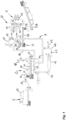
- thermo-transformation system 10 is used to perform the thermo-transformation (i.e., torrefaction) of biomass.
- the biomass feedstock may be in any appropriate format, such as sawdust, pellets, flakes, chips, etc.
- the biomass may have been screened and passed through a sieve to be within a given range of granulometry.
- the moisture content of the biomass may be between 20% and 60%, with a range of optimal operation being between 25-40%.
- the biomass may originate from wood, agricultural residues, recycled wood, compost, etc.
- the biomass feedstock may be predried if necessary to reach an appropriate moisture content for being subjected to torrefaction in the thermo-transformation system 10.
- a predrying stage is shown as an example hereinafter.
- the thermo-transformation system 10 comprises a conditioning stage 12 and a torrefaction stage 13.
- the stages are interrelated by a pneumatic circuit 14.
- a condensing unit 15 may be used with the pneumatic circuit 14 to remove condensate from synthesis gases in the pneumatic circuit 14, and regulate a temperature thereof.
- a pre-drying stage 16 may be located upstream of the conditioning stage 12 to pre-dry biomass feedstock prior to feeding same to the conditioning stage 12.
- the conditioning stage 12 is the biomass inlet of the system 10 and increases the temperature of the biomass feedstock.
- the torrefaction stage 13 is the biomass outlet of the system 10 and thermally transforms the biomass.
- the pneumatic circuit 14 displaces the biomass between the conditioning stage 12 and the torrefaction stage 13 (e.g., at a range of 10,2 - 20,4 m/s). Moreover, the pneumatic circuit 14 provides heat in the form of combustion gases to drive the torrefaction stage 13.
- the conditioning stage 12 comprises an inlet 20.
- the inlet 20 is a funnel that may be used with a hopper, a conveyor, bulk bags, or any other appropriate apparatus or format in which the biomass will be fed to the system 10.
- the biomass is in the form of sawdust.
- a rotary valve 21 is at a bottom of the inlet 20 and interfaces the inlet 20 to a feed screw unit 22. Therefore, the rotary valve 21 controls the feed rate of the biomass feedstock to the feed screw unit 22.
- the feed screw unit 22 may comprise any appropriate feed screw, namely an endless screw within a cylindrical conduit, in addition to an actuator.
- the actuation of the endless screw i.e., rotation
- the feed screw unit 22 may comprise a double or twin feed screw to increase the throughput of biomass in the conditioning stage 12 (e.g., 10-25 Hz).
- the feed screw unit 22 may further have a sleeve 24 to heat the mass moving in the cylindrical conduit.
- An inlet of the sleeve 24 is at an upstream end of the feed screw unit 22, whereby the flow of combustion gases (a.k.a., flue gas) in the sleeve 24 is in the same direction as that of the biomass.
- a screw-like path may be defined by the insertion of baffle walls within the sleeve 24 (for instance forming a spiral path), increasing the time of residency of the hot air in the sleeve 24.
- a water injection unit may also be provided at the inlet 20 or outlet 23, within the rotary valve 21 (e.g., an annular nozzle).
- the water injection unit may be used to lower the temperature of the biomass, for instance if the temperature within the outlet screw unit 22 is above a predetermined threshold (a suitable range of temperatures being from 250 C to 400 C). Other methods are also considered to lower the temperature in the feed screw unit 22, such as having a part of the combustion gases bypass the sleeve 24, via bypass 25.
- the biomass circulating in the feed screw unit 22 will be exposed to high temperatures in an inert environment (i.e., low oxygen).
- the sealed rotary valve 21 may limit the infiltration of oxygen into the system 10. For instance, the biomass is exposed to a temperature higher than a temperature of condensation of tar.
- the outlet 23 may be positioned on an underside of the cylinder of the feed screw unit 22.
- a continuous feed of conditioned biomass is as a result dropped out of the feed screw unit 22, and will be transported to the torrefaction stage 13 by the pneumatic conveyor 14, as described in further detail hereinafter.
- the torrefaction stage 13 comprises one or more cyclonic bed reactors 30 (a.k.a., torrefaction reactor 30), with of the cyclonic bed reactors being illustrated in Fig. 1 .
- the torrefaction stage 13 may comprise one or more of the torrefaction reactors 30, or any other torrefaction apparatus.
- the biomass is exposed to combustion gases, during at least a minimum time of residency.
- the combustion gases are at any appropriate temperature to have a torrefying effect on the biomass.
- the combustion gases are at a temperature ranging between 300 and 500°C, although temperatures outside this range may be appropriate as well in certain circumstances.
- the cyclonic bed reactors 30 may be similar in configuration to the filtration apparatus described in US patent application publication no. 2011/0239861 .
- the torrefaction reactor 30 may be broadly described as having a casing defining an inner cavity with an upper cylindrical portion, and a lower hopper portion connected to the upper cylindrical portion.
- the inlet is in the upper cylindrical portion for feeding a flow of gas and the biomass into the inner cavity.
- the inlet is positioned with respect to the casing to cause movement of the biomass in a downward spiral path in the casing.
- a solids outlet is at a bottom of the lower hopper portion for outletting the biomass from the casing.
- a gas outlet is in the upper cylindrical portion to exhaust gases from the casing.
- ports i.e., a pair of sustentation rings, although one or more are possible
- the ports are oriented so as to guide these other gas into following a path at least partially vertical when entering the inner cavity to disrupt the movement of the solids in the downward spiral path.
- the gases injected through the ports of the sustentation ring may increase the residency time of the biomass in the reactor 30.
- the ports have a vertical component in their orientation, to guide the gases upwardly, and in the spiral path.
- US patent application publication no. 2011/0239861 describes a filtration configuration at an upper end of the support wall of the filtration apparatus.
- the cyclonic bed reactor 30 may have a different filtration configuration, or even limited or no filtration.
- a feed screw unit 31A may be located at the bottom of the reactors 30 to collect the dry thermo-transformed biomass exiting from the torrefaction reactors 30, and to cool off the biomass.
- a second screw unit 31B may be used to cool off the biomass.
- a water injection unit may also be provided adjacent to an upstream end of the second screw unit 31B. The water injection unit may be used to lower the temperature of the biomass, for instance if the temperature within the second screw unit 31B is above a predetermined threshold.
- a cooling fluid e.g., water, air
- a rotary valve 32 may be positioned at the outlet of the feed screw unit 31, thereby minimizing gas leaks at the outlet of the torrefaction reactors 30, and controlling the torrefied biomass output rate.
- the system 10 may be provided with multiple feed screw units 31, for instance with one for each of the torrefaction reactors 30.
- rotary valves 21 and 32 at the inlet and the outlet of the system 10 reduces and/or prevents oxygen infiltration in the system 10, thereby helping in preserving an inert environment to avoid combustion of the biomass during torrefaction.
- the feed screw units 31A and 31B, or like mechanism, are used to reduce the temperature of the biomass, to reduce the risk of combustion of the biomass when exposed to oxygen at the outlet of the system 10.
- any other configuration of reactor may be used in the torrefaction stage 13 to expose the biomass to combustion gases.
- a rotary drum reactor may be operated, or air conveyors may be used provided they have sufficient length to respect the residency time of the biomass, and thus allow sufficient exposure of the biomass to combustion gases.
- the torrefaction reactors 30 are well-suited for being used with a continuous feed of biomass from the conditioning stage 12.
- the pneumatic circuit 14 comprises an air conveyor 40 extending from the outlet of the feed screw unit 22 to the inlet of the cyclonic bed reactors 30. Accordingly, the biomass flows to the reactors 30 as entrained by a flow of combustion gases (a.k.a. flue gases), and torrefaction gases emanating from the torrefaction of the biomass. More, specifically, the pneumatic circuit 14 has return pipes 41 collecting gases exhausted by the torrefaction reactors 30, whereby the synthesis gases (i.e., syngas) circulating in the pneumatic circuit 14 are a mixture of combustion gases and torrefaction gases. The gases collected at the exhaust are generally hot, with some humidity and generally without airborne dust, as the reactors 30 typically perform some form of filtration.
- combustion gases a.k.a. flue gases
- torrefaction gases emanating from the torrefaction of the biomass.
- the pneumatic circuit 14 has return pipes 41 collecting gases exhausted by the torrefaction reactors 30, whereby the synthesis gases (i.e
- a fan 42 in the return pipes 41 ensures that the flow of gases is of sufficient magnitude in the circuit 14 to cause the movement of the biomass.
- the fan 42 may be one of numerous fans in the circuit 14.
- a reactor branch 43 diverges from the return pipes 41 and feeds some gases to the reactors 30 and more specifically to the sustentation ring of the reactors 30.
- the return pipes 41 converge to a single return pipe also labeled 41, which return pipe connects to the inlet of the air conveyor 40.
- a burner branch 44 diverges from the return pipe 41 and is connected to a burner 45. Hence, the burner branch 44 feeds combustion gases and/or torrefaction gases to the burner 45.
- the burner 45 is a combustion burner. Gases exhausted by the torrefaction reactors 30 (i.e, combustion gases and/or torrefaction gases or synthesis gases (syngas)) may be fed into the combustion chamber of the burner 45 through an annular vortex to raise the resident time and combustion efficiency.
- a fresh air intake 46 is also associated to the burner 45, for instance to adjust the amount of oxygen fed to the burner 45 for efficient combustion.
- An external fuel (natural gas, fuel oil, propane, etc) may be used to start the process and to maintain a pilot flame into the combustion chamber of the burner 45.
- a feed pipe 47 relates the burner 45 to the sleeve 24 of the conditioning stage 12.
- the sleeve 24 may have an exhaust pipe 48 to exhaust some of the combustion gases from the pneumatic circuit 14.
- the biomass is exposed to synthesis gases.
- the biomass feedstock exiting the conditioning stage 12 has a reduced moisture content, whereby the thermal transformation reaction of the biomass feedstock is initiated when it reaches the air conveyor 40 of the conveyor pneumatic circuit 14, and continues in the torrefaction reactors 30 or like apparatus. There may be some flash evaporation of the moisture in the biomass when it reaches the air conveyor 40 of the conveyor pneumatic circuit 14.
- Torrefaction gases emanating from the biomass may be directed to the burner 45, to be part of the combustion. Hence, the torrefaction gases are used to produce heat for both stages 12 and 13.
- the use of rotary valves 21 and 32 reduce the amount of oxygen entering the system 10.
- a condensing unit 15 has water-cooled combustion gas condenser 50 that may be provided as branching off from the pneumatic circuit 14.
- the condenser 50 receives systhesis gases from the return pipe 41, but may be located elsewhere in the pneumatic circuit 14.
- the condenser 50 is used to condensate humidity in the syngas resulting from the torrefaction process, and may hence be located in proximity of the torrefaction reactors 30.
- the condenser 50 may regulate the temperature of the syngas/combustion gas by its heat capacity.
- the combustion gases enter the condenser 50.
- the condenser 50 is configured with respect to a feed pipe 51 such that the synthesis gases enter tangentially via an upper portion of the condenser 50.
- the outlet 52 is equipped with a coil 53 of refrigerant, such as a glycol cooled coil. In an embodiment, outside surfaces of the coil 53 have a double wall jacket with cooling glycol.
- the condenser 50 may be equipped with a self-cleaning blow back system with appropriate injection nozzles.
- the heat recuperated by the coil 53 may be used for heating purposes.
- one or more heating units 54 of the type having a coil and fan is shown, although other arrangements are considered as well.
- a return pipe 55 may then direct the combustion gases to the pneumatic circuit 14.
- An appropriate draining circuit may then be used to collect the condensate.
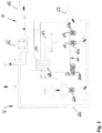
- the pre-drying stage 16 is shown in greater detail, and may optionally be used to pre-dry biomass feedstock to a suitable moisture content (e.g., 25% to 40%).
- the pre-drying stage may be comprises of any type of dryers, e.g. rotary dryers, belt dryers or flash dryers.
- the pre-drying stage 16 essentially comprises a dryer 60 defining a chamber in which the biomass feedstock is exposed to hot air, with mixing features operated by motor 60A (e.g., a screw, etc).
- the dryer 60 has a dryer inlet 61, a recirculating outlet 62 (with rotary valve 62A or equivalent) and a dryer outlet 63 (with rotary valve 63A or equivalent), with both outlets 62 and 63 being in a bottom of the dryer 60.
- the stage 16 further comprises a pneumatic circuit 64 in association with the dryer 60 to provide hot air, a flow of biomass, and a conveying flow for recirculation of biomass.
- the dryer 60 and the circuit 64 form a generally hermetic unit, so as to limit air infiltration causing heat loss.
- the pneumatic circuit 64 has an air inlet, followed by a heat exchanger 65 to heat the air from the inlet.
- the circuit 64 has appropriate piping to direct the heated air from the heat exchanger 65 to the reactor inlet 61.
- a biomass source converges with the circuit 64.
- the biomass source may comprise a hopper, a funnel and a rotary valve 66A or equivalent, to control the amount of biomass entering the circuit 64.
- the piping of the pneumatic circuit 64 is also fluidly connected to the recirculating outlet 62, with the rotary valve 62A controlling the amount of biomass recirculating via the circuit 64.
- the piping of the pneumatic circuit 64 then reaches the inlet 61, to discharge a mix of fresh biomass and recirculated biomass, in the flow of hot air.
- the recirculation of the biomass is performed to expose all biomass to hot air and thus promote uniform temperature condition of the biomass.
- a portion of the biomass may exit the reactor 60 via the reactor outlet 63, with the rotary valve 63A controlling the amount of biomass exiting the stage 16.
- a conveyor 67 may then feed the pre-dried biomass to the conditioning stage 12.
- the heat exchanger 65 may receive combustion gases from the pneumatic circuit 14 ( Fig. 1 ), for instance combustion gases that are to be exhausted, to recuperate heat therefrom. It is also possible to use any appropriate source of heat, for instance independent of the pneumatic circuit 14, to heat the air in the stage 16. For instance, electric coils may be used.
- a filtration unit 68 with blowback may be provided to remove dust and airborne particles from the reactor 60.
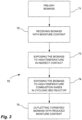
- a water injection unit 69 may be used to extinguish a fire. Referring to Fig. 3 , there is illustrated at 70 a method for thermo-transformation (i.e., torrefaction) of biomass.
- the biomass may be pre-dried to reach a suitable temperature or reduce its humidity content, if necessary.
- step 72 the biomass is received in a sawdust format.
- the biomass is exposed to a high temperature by indirect contact (e.g., temperature above the temperature of condensation of tar), whereby the biomass feedstock is heated and its moisture content may be reduced.
- a high temperature e.g., temperature above the temperature of condensation of tar
- the biomass that is exposed to these conditions is a continuous feed of biomass.
- step 74 the biomass is directly exposed to a high-temperature combustion gas flow (a.k.a., flue gases) and residual torrefaction gases, with low static pressure.
- a high-temperature combustion gas flow a.k.a., flue gases
- residual torrefaction gases with low static pressure.
- the biomass feedstock undergoes thermo-transformation, by which the chemical structures of the biomass may be broken (i.e., lignin, cellulose, hemi-cellulose).
- Volatile organic compounds may be vaporized after the two stages, thereby improving the condition of the biomass for combustion.
- Moisture may further evaporate from the biomass. For example, flash evaporation of moisture in the biomass may occur.
- the biomass is outlet with a reduced moisture content.
- the biomass may be subjected to a cooling stage. It is pointed out that the biomass may be exposed to an inert environment (i.e., negligible level of oxygen) in steps 74 and/or 75.
- the resulting torrefied biomass may be in any appropriate format.
- the torrefied biomass is in a sawdust state, although it could be in flakes, granules, pellets or the like.
- the torrefied biomass may be used in any appropriate application.
- the torrefied biomass may be used as a fuel in combustion.
- Applications include non-exclusively co-firing in large coal power plants, heavy fuel oil substitution, partial substitute for coke in carbon anodes, blast furnaces, iron ore pellets, activated carbon for gas purification, gold purification, metal extraction and many other applications, soil amendment and soil remediation (mining site rehabilitation), among numerous possibilities.
Landscapes
- Chemical & Material Sciences (AREA)
- Oil, Petroleum & Natural Gas (AREA)
- Organic Chemistry (AREA)
- Life Sciences & Earth Sciences (AREA)
- Engineering & Computer Science (AREA)
- Forests & Forestry (AREA)
- Biodiversity & Conservation Biology (AREA)
- Ecology (AREA)
- Agronomy & Crop Science (AREA)
- Wood Science & Technology (AREA)
- Physics & Mathematics (AREA)
- Thermal Sciences (AREA)
- Combustion & Propulsion (AREA)
- Treatment Of Sludge (AREA)
- Processing Of Solid Wastes (AREA)
- Apparatus Associated With Microorganisms And Enzymes (AREA)
Claims (14)
- Procédé pour la torréfaction d'une biomasse comprenant :la réception d'une biomasse présentant une teneur en humidité donnée ;le chauffage de la biomasse dans un environnement généralement inerte par contact indirect ;ensuite la torréfaction de la biomasse par l'exposition de la biomasse à un flux de gaz de combustion dans l'environnement généralement inerte, en faisant circuler la biomasse dans un flux cyclonique ; etla sortie de la biomasse ayant un taux d'humidité réduit.
- Procédé selon la revendication 1, dans lequel le chauffage de la biomasse par contact indirect comprend la mise en circulation de la biomasse dans un conduit entouré d'un manchon chauffé.
- Procédé selon la revendication 2, dans lequel le chauffage de la biomasse comprend l'acheminement des gaz de combustion dans le manchon chauffé.
- Procédé selon l'une quelconque des revendications 2 et 3, dans lequel la mise en circulation de la biomasse dans le conduit comprend le transport de la biomasse avec une vis d'alimentation.
- Procédé selon l'une quelconque des revendications 1 à 4, dans lequel le chauffage de la biomasse comprend le chauffage de la biomasse à une température allant de 250 °C à 400 °C.
- Procédé selon l'une quelconque des revendications précédentes, dans lequel la mise en circulation de la biomasse dans un flux cyclonique comprend l'exposition de la biomasse à un vortex annulaire des gaz de combustion dans le flux cyclonique pour augmenter un temps de séjour de la biomasse dans le flux cyclonique.
- Procédé selon l'une quelconque des revendications 1 à 6, dans lequel la torréfaction de la biomasse comprend l'exposition de la biomasse à une température allant de 300 °C à 500 °C par l'exposition de la biomasse aux gaz de combustion.
- Procédé selon l'une quelconque des revendications 1 à 7, comprenant en outre le refroidissement de la biomasse après la sortie en transportant la biomasse dans une unité à vis d'alimentation.
- Procédé selon l'une quelconque des revendications 1 à 8, dans lequel la sortie de la biomasse comprend la mise en fonctionnement d'une vanne rotative pour réguler une quantité de biomasse de sortie.
- Procédé selon l'une quelconque des revendications 1 à 9, comprenant en outre le séchage de la biomasse avant de chauffer la biomasse par contact indirect.
- Procédé selon la revendication 10, dans lequel le séchage de la biomasse comprend au moins un parmi le mélange et la remise en circulation de la biomasse à l'intérieur d'une chambre d'un réacteur tout en exposant la biomasse à de l'air chaud.
- Procédé selon l'une quelconque des revendications 10 et 11, dans lequel le séchage de la biomasse comprend le séchage de la biomasse jusqu'à une teneur en humidité allant de 20 % à 40 %.
- Procédé selon l'une quelconque des revendications 1 à 12, comprenant en outre la régulation d'une température des gaz de combustion utilisés pour chauffer la biomasse par contact indirect et torréfier la biomasse, par la mise en fonctionnement d'un échangeur de chaleur avec un réfrigérant dans un circuit pneumatique dans lequel les gaz de combustion circulent.
- Procédé selon l'une quelconque des revendications 1 à 13, comprenant en outre la collecte des gaz de torréfaction provenant de l'étape d'exposition de la biomasse à un flux de gaz de combustion, et dans lequel l'exposition de la biomasse à un flux de gaz de combustion comprend l'exposition de la biomasse à un flux de gaz de combustion et de gaz de torréfaction.
Applications Claiming Priority (2)
| Application Number | Priority Date | Filing Date | Title |
|---|---|---|---|
| US201261651862P | 2012-05-25 | 2012-05-25 | |
| PCT/CA2013/050402 WO2013173929A1 (fr) | 2012-05-25 | 2013-05-27 | Procédé et appareil de torréfaction de biomasse avec un réacteur à lit cyclonique |
Publications (4)
| Publication Number | Publication Date |
|---|---|
| EP2855643A1 EP2855643A1 (fr) | 2015-04-08 |
| EP2855643A4 EP2855643A4 (fr) | 2016-01-20 |
| EP2855643B1 true EP2855643B1 (fr) | 2023-06-07 |
| EP2855643C0 EP2855643C0 (fr) | 2023-06-07 |
Family
ID=49622977
Family Applications (1)
| Application Number | Title | Priority Date | Filing Date |
|---|---|---|---|
| EP13793325.5A Active EP2855643B1 (fr) | 2012-05-25 | 2013-05-27 | Procédé de torréfaction de biomasse avec un réacteur à lit cyclonique |
Country Status (6)
| Country | Link |
|---|---|
| US (2) | US9683187B2 (fr) |
| EP (1) | EP2855643B1 (fr) |
| CA (1) | CA2874789C (fr) |
| ES (1) | ES2949075T3 (fr) |
| PL (1) | PL2855643T3 (fr) |
| WO (1) | WO2013173929A1 (fr) |
Families Citing this family (7)
| Publication number | Priority date | Publication date | Assignee | Title |
|---|---|---|---|---|
| PL2855643T3 (pl) | 2012-05-25 | 2023-09-25 | Airex Energie Inc. | Sposób toryfikacji biomasy z reaktorem ze złożem cyklonowym |
| US9927174B2 (en) * | 2015-05-20 | 2018-03-27 | Geoffrey W. A. Johnson | Self Torrefied Pellet Stove |
| EP3624933A4 (fr) * | 2017-05-16 | 2021-02-17 | Massachusetts Institute of Technology | Réacteurs de conversion de biomasse et systèmes et procédés associés |
| DK3771740T3 (da) | 2019-07-31 | 2023-05-01 | Ceg Tech Uk Limited | Fremgangsmåde og apparat til en indtørringsproces |
| EP4159831A1 (fr) * | 2021-10-01 | 2023-04-05 | RWE Generation NL B.V. | Unité et procédé de torréfaction |
| WO2025107081A1 (fr) * | 2023-11-23 | 2025-05-30 | Airex Energie Inc. | Procédé et appareil de carbonisation de biomasse |
| US12590259B1 (en) * | 2025-07-21 | 2026-03-31 | WeNeW Carbology, LLC | Systems and/or methods for producing products from crop materials |
Family Cites Families (12)
| Publication number | Priority date | Publication date | Assignee | Title |
|---|---|---|---|---|
| US2848198A (en) * | 1957-01-28 | 1958-08-19 | Gen Am Transport | Fluid joint and processed material discharge assembly for rotary processing vessels |
| NL1025027C2 (nl) | 2003-12-15 | 2005-06-21 | Stichting Energie | Werkwijze en stelsel voor de productie van vaste stoffen uit grondstoffen. |
| DE102009052902A1 (de) * | 2009-04-06 | 2010-10-14 | Uhde Gmbh | Niedertemperaturpyrolyse von Biomasse in der Wirbelschicht für eine nachfolgende Flugstromvergasung |
| US8449724B2 (en) * | 2009-08-19 | 2013-05-28 | Andritz Technology And Asset Management Gmbh | Method and system for the torrefaction of lignocellulosic material |
| CA2698176C (fr) | 2010-03-30 | 2013-03-12 | Guy Prud'homme | Appareil de filtration recuperant l'energie |
| US8956426B2 (en) | 2010-04-20 | 2015-02-17 | River Basin Energy, Inc. | Method of drying biomass |
| GB2479924A (en) * | 2010-04-29 | 2011-11-02 | Mortimer Tech Holdings | Torrefaction Process |
| DE102010036425A1 (de) * | 2010-07-15 | 2012-01-19 | Polysius Ag | Vorrichtung und Verfahren zur Trocknung und Torrefizierung von wenigstens einem kohlenstoffhaltigen Stoffstrom in einem Etagenofen |
| RU2013111844A (ru) * | 2010-08-17 | 2014-09-27 | Андритц Текнолоджи Энд Эссет Менеджмент Гмбх | Способ и система для подсушивания лигноцеллюлозного материала |
| US8246788B2 (en) * | 2010-10-08 | 2012-08-21 | Teal Sales Incorporated | Biomass torrefaction system and method |
| US8203024B2 (en) * | 2011-08-23 | 2012-06-19 | Advanced Toffefaction Systems, LLC | Torrefaction systems and methods including catalytic oxidation and/or reuse of combustion gases directly in a torrefaction reactor, cooler, and/or dryer/preheater |
| PL2855643T3 (pl) | 2012-05-25 | 2023-09-25 | Airex Energie Inc. | Sposób toryfikacji biomasy z reaktorem ze złożem cyklonowym |
-
2013
- 2013-05-27 PL PL13793325.5T patent/PL2855643T3/pl unknown
- 2013-05-27 CA CA2874789A patent/CA2874789C/fr active Active
- 2013-05-27 US US14/403,795 patent/US9683187B2/en active Active
- 2013-05-27 EP EP13793325.5A patent/EP2855643B1/fr active Active
- 2013-05-27 ES ES13793325T patent/ES2949075T3/es active Active
- 2013-05-27 WO PCT/CA2013/050402 patent/WO2013173929A1/fr not_active Ceased
-
2017
- 2017-05-17 US US15/597,796 patent/US10450523B2/en active Active
Also Published As
| Publication number | Publication date |
|---|---|
| US9683187B2 (en) | 2017-06-20 |
| US10450523B2 (en) | 2019-10-22 |
| EP2855643C0 (fr) | 2023-06-07 |
| EP2855643A1 (fr) | 2015-04-08 |
| PL2855643T3 (pl) | 2023-09-25 |
| EP2855643A4 (fr) | 2016-01-20 |
| US20180023013A1 (en) | 2018-01-25 |
| CA2874789A1 (fr) | 2013-11-28 |
| CA2874789C (fr) | 2020-07-21 |
| ES2949075T3 (es) | 2023-09-25 |
| WO2013173929A1 (fr) | 2013-11-28 |
| US20150143742A1 (en) | 2015-05-28 |
Similar Documents
| Publication | Publication Date | Title |
|---|---|---|
| US10450523B2 (en) | Method and apparatus for torrefaction of biomass with a cyclonic bed reactor | |
| JP6124494B1 (ja) | 植物性バイオマス半炭化物の製造装置 | |
| CN106595250B (zh) | 生物质烘干系统与方法 | |
| US9127227B2 (en) | Method and apparatus for processing biomass material | |
| US9562204B2 (en) | Method and apparatus for pelletizing blends of biomass materials for use as fuel | |
| JP2009522097A (ja) | バイオマスを処理するための方法と装置 | |
| RU2014137447A (ru) | Автотермальное сушильное устройство, способ автотермальной усушки биомассы (варианты), способ увеличения экономической эффективности использования усушенной биомассы как топлива и способ производства пеллет из усушенной биомассы | |
| JP4393628B2 (ja) | 多段式ロータリキルン | |
| CN108779397B (zh) | 低温下使用的多架炉 | |
| US10188980B2 (en) | Coal upgrade plant and method for manufacturing upgraded coal | |
| CN111433327A (zh) | 连续生产木炭的处理和反应器 | |
| EP2912150B1 (fr) | Procédé et appareil pour mettre sous forme de pastilles des mélanges de matériaux de biomasse pour l'utilisation comme combustible | |
| JP7200703B2 (ja) | 炭化炉 | |
| JP2009138089A (ja) | 多段スクリュー炭化装置 | |
| US10976049B2 (en) | Hybrid boiler-dryer and method | |
| EP4724551A1 (fr) | Procédé et appareil de séchage de biomasse | |
| KR20100100137A (ko) | 건조 배가스 부분 순환 혼합식 열풍 건조 시스템 및 그 방법 | |
| RU2631721C1 (ru) | Установка для термической переработки твердых отходов с получением горючего газа | |
| CN110885692A (zh) | 一种连续式炭化装置及其工作方法 | |
| JPH1017312A (ja) | 炭化装置 | |
| JP4428081B2 (ja) | 有機物含有汚泥の炭化処理方法 | |
| PL233490B1 (pl) | Urządzenie do suszenia i toryfikowania substancji organicznych | |
| Taranenko et al. | Development of adaptive control system for rotary dryer at ore-processing plant JSC “Lebedinsky GOK” | |
| HK40033830A (en) | Process and reactor for continuous charcoal production |
Legal Events
| Date | Code | Title | Description |
|---|---|---|---|
| PUAI | Public reference made under article 153(3) epc to a published international application that has entered the european phase |
Free format text: ORIGINAL CODE: 0009012 |
|
| 17P | Request for examination filed |
Effective date: 20141222 |
|
| AK | Designated contracting states |
Kind code of ref document: A1 Designated state(s): AL AT BE BG CH CY CZ DE DK EE ES FI FR GB GR HR HU IE IS IT LI LT LU LV MC MK MT NL NO PL PT RO RS SE SI SK SM TR |
|
| AX | Request for extension of the european patent |
Extension state: BA ME |
|
| DAX | Request for extension of the european patent (deleted) | ||
| RA4 | Supplementary search report drawn up and despatched (corrected) |
Effective date: 20151217 |
|
| RIC1 | Information provided on ipc code assigned before grant |
Ipc: C10L 5/40 20060101ALI20151211BHEP Ipc: C10L 5/44 20060101ALI20151211BHEP Ipc: C10L 9/08 20060101AFI20151211BHEP |
|
| STAA | Information on the status of an ep patent application or granted ep patent |
Free format text: STATUS: EXAMINATION IS IN PROGRESS |
|
| 17Q | First examination report despatched |
Effective date: 20180216 |
|
| GRAP | Despatch of communication of intention to grant a patent |
Free format text: ORIGINAL CODE: EPIDOSNIGR1 |
|
| STAA | Information on the status of an ep patent application or granted ep patent |
Free format text: STATUS: GRANT OF PATENT IS INTENDED |
|
| INTG | Intention to grant announced |
Effective date: 20221111 |
|
| GRAS | Grant fee paid |
Free format text: ORIGINAL CODE: EPIDOSNIGR3 |
|
| GRAA | (expected) grant |
Free format text: ORIGINAL CODE: 0009210 |
|
| STAA | Information on the status of an ep patent application or granted ep patent |
Free format text: STATUS: THE PATENT HAS BEEN GRANTED |
|
| AK | Designated contracting states |
Kind code of ref document: B1 Designated state(s): AL AT BE BG CH CY CZ DE DK EE ES FI FR GB GR HR HU IE IS IT LI LT LU LV MC MK MT NL NO PL PT RO RS SE SI SK SM TR |
|
| REG | Reference to a national code |
Ref country code: GB Ref legal event code: FG4D |
|
| REG | Reference to a national code |
Ref country code: CH Ref legal event code: EP Ref country code: AT Ref legal event code: REF Ref document number: 1575030 Country of ref document: AT Kind code of ref document: T Effective date: 20230615 |
|
| REG | Reference to a national code |
Ref country code: DE Ref legal event code: R096 Ref document number: 602013083948 Country of ref document: DE |
|
| REG | Reference to a national code |
Ref country code: NO Ref legal event code: T2 Effective date: 20230607 |
|
| U01 | Request for unitary effect filed |
Effective date: 20230703 |
|
| U07 | Unitary effect registered |
Designated state(s): AT BE BG DE DK EE FI FR IT LT LU LV MT NL PT SE SI Effective date: 20230802 |
|
| REG | Reference to a national code |
Ref country code: LT Ref legal event code: MG9D Ref country code: ES Ref legal event code: FG2A Ref document number: 2949075 Country of ref document: ES Kind code of ref document: T3 Effective date: 20230925 |
|
| PG25 | Lapsed in a contracting state [announced via postgrant information from national office to epo] |
Ref country code: RS Free format text: LAPSE BECAUSE OF FAILURE TO SUBMIT A TRANSLATION OF THE DESCRIPTION OR TO PAY THE FEE WITHIN THE PRESCRIBED TIME-LIMIT Effective date: 20230607 Ref country code: HR Free format text: LAPSE BECAUSE OF FAILURE TO SUBMIT A TRANSLATION OF THE DESCRIPTION OR TO PAY THE FEE WITHIN THE PRESCRIBED TIME-LIMIT Effective date: 20230607 Ref country code: GR Free format text: LAPSE BECAUSE OF FAILURE TO SUBMIT A TRANSLATION OF THE DESCRIPTION OR TO PAY THE FEE WITHIN THE PRESCRIBED TIME-LIMIT Effective date: 20230908 |
|
| PG25 | Lapsed in a contracting state [announced via postgrant information from national office to epo] |
Ref country code: SK Free format text: LAPSE BECAUSE OF FAILURE TO SUBMIT A TRANSLATION OF THE DESCRIPTION OR TO PAY THE FEE WITHIN THE PRESCRIBED TIME-LIMIT Effective date: 20230607 |
|
| PG25 | Lapsed in a contracting state [announced via postgrant information from national office to epo] |
Ref country code: IS Free format text: LAPSE BECAUSE OF FAILURE TO SUBMIT A TRANSLATION OF THE DESCRIPTION OR TO PAY THE FEE WITHIN THE PRESCRIBED TIME-LIMIT Effective date: 20231007 |
|
| PG25 | Lapsed in a contracting state [announced via postgrant information from national office to epo] |
Ref country code: SM Free format text: LAPSE BECAUSE OF FAILURE TO SUBMIT A TRANSLATION OF THE DESCRIPTION OR TO PAY THE FEE WITHIN THE PRESCRIBED TIME-LIMIT Effective date: 20230607 Ref country code: SK Free format text: LAPSE BECAUSE OF FAILURE TO SUBMIT A TRANSLATION OF THE DESCRIPTION OR TO PAY THE FEE WITHIN THE PRESCRIBED TIME-LIMIT Effective date: 20230607 Ref country code: IS Free format text: LAPSE BECAUSE OF FAILURE TO SUBMIT A TRANSLATION OF THE DESCRIPTION OR TO PAY THE FEE WITHIN THE PRESCRIBED TIME-LIMIT Effective date: 20231007 Ref country code: CZ Free format text: LAPSE BECAUSE OF FAILURE TO SUBMIT A TRANSLATION OF THE DESCRIPTION OR TO PAY THE FEE WITHIN THE PRESCRIBED TIME-LIMIT Effective date: 20230607 |
|
| REG | Reference to a national code |
Ref country code: DE Ref legal event code: R097 Ref document number: 602013083948 Country of ref document: DE |
|
| PLBE | No opposition filed within time limit |
Free format text: ORIGINAL CODE: 0009261 |
|
| STAA | Information on the status of an ep patent application or granted ep patent |
Free format text: STATUS: NO OPPOSITION FILED WITHIN TIME LIMIT |
|
| 26N | No opposition filed |
Effective date: 20240308 |
|
| U20 | Renewal fee for the european patent with unitary effect paid |
Year of fee payment: 12 Effective date: 20240527 |
|
| REG | Reference to a national code |
Ref country code: CH Ref legal event code: PL |
|
| PG25 | Lapsed in a contracting state [announced via postgrant information from national office to epo] |
Ref country code: MC Free format text: LAPSE BECAUSE OF FAILURE TO SUBMIT A TRANSLATION OF THE DESCRIPTION OR TO PAY THE FEE WITHIN THE PRESCRIBED TIME-LIMIT Effective date: 20230607 |
|
| GBPC | Gb: european patent ceased through non-payment of renewal fee |
Effective date: 20240527 |
|
| PG25 | Lapsed in a contracting state [announced via postgrant information from national office to epo] |
Ref country code: MC Free format text: LAPSE BECAUSE OF FAILURE TO SUBMIT A TRANSLATION OF THE DESCRIPTION OR TO PAY THE FEE WITHIN THE PRESCRIBED TIME-LIMIT Effective date: 20230607 Ref country code: CH Free format text: LAPSE BECAUSE OF NON-PAYMENT OF DUE FEES Effective date: 20240531 |
|
| PG25 | Lapsed in a contracting state [announced via postgrant information from national office to epo] |
Ref country code: IE Free format text: LAPSE BECAUSE OF NON-PAYMENT OF DUE FEES Effective date: 20240527 |
|
| PGFP | Annual fee paid to national office [announced via postgrant information from national office to epo] |
Ref country code: PL Payment date: 20250328 Year of fee payment: 13 |
|
| PG25 | Lapsed in a contracting state [announced via postgrant information from national office to epo] |
Ref country code: GB Free format text: LAPSE BECAUSE OF NON-PAYMENT OF DUE FEES Effective date: 20240527 |
|
| U20 | Renewal fee for the european patent with unitary effect paid |
Year of fee payment: 13 Effective date: 20250407 |
|
| REG | Reference to a national code |
Ref country code: GB Ref legal event code: S28 Free format text: APPLICATION FILED |
|
| PGFP | Annual fee paid to national office [announced via postgrant information from national office to epo] |
Ref country code: ES Payment date: 20250605 Year of fee payment: 13 |
|
| PGFP | Annual fee paid to national office [announced via postgrant information from national office to epo] |
Ref country code: NO Payment date: 20250509 Year of fee payment: 13 |
|
| PGFP | Annual fee paid to national office [announced via postgrant information from national office to epo] |
Ref country code: RO Payment date: 20250422 Year of fee payment: 13 |
|
| PG25 | Lapsed in a contracting state [announced via postgrant information from national office to epo] |
Ref country code: HU Free format text: LAPSE BECAUSE OF FAILURE TO SUBMIT A TRANSLATION OF THE DESCRIPTION OR TO PAY THE FEE WITHIN THE PRESCRIBED TIME-LIMIT; INVALID AB INITIO Effective date: 20130527 |
|
| PG25 | Lapsed in a contracting state [announced via postgrant information from national office to epo] |
Ref country code: CY Free format text: LAPSE BECAUSE OF FAILURE TO SUBMIT A TRANSLATION OF THE DESCRIPTION OR TO PAY THE FEE WITHIN THE PRESCRIBED TIME-LIMIT; INVALID AB INITIO Effective date: 20130527 |
|
| PG25 | Lapsed in a contracting state [announced via postgrant information from national office to epo] |
Ref country code: GB Free format text: LAPSE BECAUSE OF NON-PAYMENT OF DUE FEES Effective date: 20240527 |
|
| PGRI | Patent reinstated in contracting state [announced from national office to epo] |
Ref country code: GB Effective date: 20250930 |
|
| REG | Reference to a national code |
Ref country code: GB Ref legal event code: S28 Free format text: RESTORATION ALLOWED Effective date: 20250930 |