EP2855808B1 - Serrure à ressort - Google Patents
Serrure à ressort Download PDFInfo
- Publication number
- EP2855808B1 EP2855808B1 EP13800833.9A EP13800833A EP2855808B1 EP 2855808 B1 EP2855808 B1 EP 2855808B1 EP 13800833 A EP13800833 A EP 13800833A EP 2855808 B1 EP2855808 B1 EP 2855808B1
- Authority
- EP
- European Patent Office
- Prior art keywords
- keeper
- latch
- latch bolt
- slam
- bolt
- Prior art date
- Legal status (The legal status is an assumption and is not a legal conclusion. Google has not performed a legal analysis and makes no representation as to the accuracy of the status listed.)
- Active
Links
Images




Classifications
-
- E—FIXED CONSTRUCTIONS
- E05—LOCKS; KEYS; WINDOW OR DOOR FITTINGS; SAFES
- E05C—BOLTS OR FASTENING DEVICES FOR WINGS, SPECIALLY FOR DOORS OR WINDOWS
- E05C1/00—Fastening devices with bolts moving rectilinearly
- E05C1/08—Fastening devices with bolts moving rectilinearly with latching action
-
- E—FIXED CONSTRUCTIONS
- E05—LOCKS; KEYS; WINDOW OR DOOR FITTINGS; SAFES
- E05B—LOCKS; ACCESSORIES THEREFOR; HANDCUFFS
- E05B17/00—Accessories in connection with locks
- E05B17/0045—Silencing devices; Noise reduction
-
- E—FIXED CONSTRUCTIONS
- E05—LOCKS; KEYS; WINDOW OR DOOR FITTINGS; SAFES
- E05B—LOCKS; ACCESSORIES THEREFOR; HANDCUFFS
- E05B65/00—Locks or fastenings for special use
- E05B65/0007—Locks or fastenings for special use for gates
-
- E—FIXED CONSTRUCTIONS
- E05—LOCKS; KEYS; WINDOW OR DOOR FITTINGS; SAFES
- E05C—BOLTS OR FASTENING DEVICES FOR WINGS, SPECIALLY FOR DOORS OR WINDOWS
- E05C1/00—Fastening devices with bolts moving rectilinearly
- E05C1/08—Fastening devices with bolts moving rectilinearly with latching action
- E05C1/10—Fastening devices with bolts moving rectilinearly with latching action with operating handle or equivalent member rigid with the latch
-
- E—FIXED CONSTRUCTIONS
- E05—LOCKS; KEYS; WINDOW OR DOOR FITTINGS; SAFES
- E05B—LOCKS; ACCESSORIES THEREFOR; HANDCUFFS
- E05B15/00—Other details of locks; Parts for engagement by bolts of fastening devices
- E05B15/02—Striking-plates; Keepers; Bolt staples; Escutcheons
- E05B15/0205—Striking-plates, keepers, staples
-
- Y—GENERAL TAGGING OF NEW TECHNOLOGICAL DEVELOPMENTS; GENERAL TAGGING OF CROSS-SECTIONAL TECHNOLOGIES SPANNING OVER SEVERAL SECTIONS OF THE IPC; TECHNICAL SUBJECTS COVERED BY FORMER USPC CROSS-REFERENCE ART COLLECTIONS [XRACs] AND DIGESTS
- Y10—TECHNICAL SUBJECTS COVERED BY FORMER USPC
- Y10T—TECHNICAL SUBJECTS COVERED BY FORMER US CLASSIFICATION
- Y10T292/00—Closure fasteners
- Y10T292/08—Bolts
- Y10T292/096—Sliding
-
- Y—GENERAL TAGGING OF NEW TECHNOLOGICAL DEVELOPMENTS; GENERAL TAGGING OF CROSS-SECTIONAL TECHNOLOGIES SPANNING OVER SEVERAL SECTIONS OF THE IPC; TECHNICAL SUBJECTS COVERED BY FORMER USPC CROSS-REFERENCE ART COLLECTIONS [XRACs] AND DIGESTS
- Y10—TECHNICAL SUBJECTS COVERED BY FORMER USPC
- Y10T—TECHNICAL SUBJECTS COVERED BY FORMER US CLASSIFICATION
- Y10T292/00—Closure fasteners
- Y10T292/08—Bolts
- Y10T292/096—Sliding
- Y10T292/1014—Operating means
-
- Y—GENERAL TAGGING OF NEW TECHNOLOGICAL DEVELOPMENTS; GENERAL TAGGING OF CROSS-SECTIONAL TECHNOLOGIES SPANNING OVER SEVERAL SECTIONS OF THE IPC; TECHNICAL SUBJECTS COVERED BY FORMER USPC CROSS-REFERENCE ART COLLECTIONS [XRACs] AND DIGESTS
- Y10—TECHNICAL SUBJECTS COVERED BY FORMER USPC
- Y10T—TECHNICAL SUBJECTS COVERED BY FORMER US CLASSIFICATION
- Y10T292/00—Closure fasteners
- Y10T292/08—Bolts
- Y10T292/096—Sliding
- Y10T292/1014—Operating means
- Y10T292/1016—Cam
Definitions
- the present invention relates to a slam latch and to methods of operating a gate/panel using the slam latch.
- Conventional slam latches contain a spring-loaded latch bolt which is caught, for example, within a keeper (striker plate) when a door or panel is closed or slammed shut.
- a keeper striker plate
- the latch bolt strikes against an inclined surface or keeper being angulated towards the direction of bolt reciprocation. This causes the latch bolt to retreat within the main mounting body holding the latch bolt and simultaneously compresses the spring.
- the door or panel continues to close until the latch bolt aligns with an opening contained within a surface (especially a planar surface) of the keeper, allowing the spring-loaded bolt to propel outwards until the latch bolt is contained within the keeper opening, thereby securing the door or panel.
- the doors or panels are predominantly constructed of steel and, in agricultural applications, must be strong enough to safely restrain any animals being handled.
- slam latch bolts are conventionally accommodated in a keeper opening that is larger than the latch bolt. Due to the speed and momentum of the door or panel as it is closed, such an oversize keeper opening is designed to allow sufficient time for the spring loaded latch bolt to propel outwards and locate within the opening and prevent the door or panel from traveling past the opening. However, this excessive gap may cause a rattle which causes additional stress to an animal.
- operators may prefer to guide or push a door or panel shut, and often this is achieved by the operator holding or maintaining contact with the handle of the slam latch.
- the operator's hand in particular may be subjected to high impact shock stress. This may cause operators to use the slam latch by closing the door or panel with less control (as to avoid shock stress the operator may not maintain contact with the door or panel), or it may discourage long term use.
- this may occasionally impede the spring-return function of the latch bolt.
- US 1,318,988 discloses a door adjuster for holding doors close to their stops, thus allowing for swelling and shrinking and preventing the doors from rattling.
- the door adjuster is mountable within the keeper of a mortise door lock.
- the door adjuster of this document has an inclined edge, which is intended to abut against the edge of a latch bolt to push the door against its stop.
- the latch described in US 1,318,988 is not suited to prevent rattling for doors in which there is no door jamb.
- US 2,542,130 discloses a lock set for use with doors having a door jamb.
- the lock set described in this document is unsuitable to prevent rattling for doors in which there is no door jamb.
- US 3,955,837 discloses a latch, and especially a farm gate latch.
- the latch described in this document is unsuitable to prevent rattling.
- a slam latch comprising:
- the slam latch as described herein is particularly suited for securing doors and swinging panels, particularly in agricultural applications (eg. for handling livestock), but it may have other non-agricultural commercial uses.
- the slam latch is used for locking panels in an animal crush, especially a cattle crush.
- the mounting body may be of any suitable size, shape and construction, and may be made of any suitable type of material or materials (such as plastics material or metal, such as steel).
- the mounting body comprises a mounting support and optionally a mounting cover.
- the spaced sides of the mounting support may define a channel/passageway for accommodating a latch bolt, especially a cuboid (rectangular) latch bolt.
- the mounting cover may be fastenable to the mounting support to define a channel/passageway for the bolt.
- the bolt may be held in a single plane by the mounting body (which advantageously provides a more robust/sturdy latch that is less susceptible to bending moments).
- the mounting body may enclose all or almost all moving parts, leading to improved safety.
- the mounting body may define a channel/passageway for accommodating a latch bolt, especially a cuboid (rectangular) latch bolt.
- the mounting body may be integrally formed.
- the passageway may be machined out of a solid piece of metal.
- the bolt is held in a single plane by the mounting body (which advantageously provides a more robust/sturdy latch that is less susceptible to bending moments).
- the mounting body may enclose all or almost all moving parts, leading to improved safety.
- the mounting body or support may have at least one opening through which one or more fasteners may extend to mount the mounting body, plate or support to a gate, flap, door or other type of movable or hinged panel, or any type of fixture such as a post, jamb, wall or framework, for example.
- the mounting body would be mounted to a moveable gate, flap, door or panel, whereas the keeper would be mounted to or integrated into a non-movable fixture such as a post, fence, pen or animal crush, for example.
- this arrangement may be reversed, such as where the mounting body may be on the non-movable fixture and the keeper may be mounted to a moveable gate, flap, door or panel.
- the latch bolt may be of any suitable size, shape and construction, and may be made of any suitable type of material or materials (such as plastics material or metal (such as steel)).
- the latch bolt may be of any shape provided that it is long enough and able to be moved between the locking and unlocking positions.
- the latch bolt may be any suitable shape and may be a cylindrical and/or cuboid (rectangular) rod, pin or bar, for example.
- the latch bolt may comprise a shaft region and a keeper-engaging region extending from the shaft region.
- the keeper-engaging region terminates at a keeper-engaging end.
- the shaft region may be of any suitable shape, including cylindrical (round) or cuboid (rectangular).
- the keeper-engaging region (and the keeper engaging end) may also be of any suitable shape, including cylindrical (round) or cuboid (rectangular).
- the latch bolt may be especially formed of a single, solid material, in which the material is especially metal, more especially steel.
- the latch bolt has a cuboid (rectangular) shape overall, although it may include cut-outs or slots as discussed further below.
- the latch bolt is "A" shaped, wherein an apex of the "A" is the keeper-engaging end.
- the keeper-engaging region is of decreased cross-sectional area at the keeper-engaging end.
- the keeper-engaging region may be tapered to an angle of about 4, 5, 6, 7, 8, 9, 10, 11, 12, 13, 14, 15, 16, 17, 18, 19 or 20 degrees relative to the longitudinal axis.
- the taper may be approximately 3, 4, 5, 6, 7, 8, 9, 10, 11 or 12 mm in length (as measured along the longitudinal axis), but it need not be limited to this length.
- the keeper-engaging region is tapered on one or more longitudinal sides, including 1, 2, or 3 longitudinal sides, especially 1 or 2 longitudinal sides. If the keeper-engaging region is tapered on more than one longitudinal sides, the taper may be the same on each longitudinal side or different.
- the keeper-engaging region is tapered on only one longitudinal side. According to the invention the keeper-engaging region is at least tapered on the longitudinal side that first strikes the keeper as the latch moves to a locking position.
- the shape of the keeper-engaging region will be snugly received within a suitably shaped opening in the keeper.
- the inventors have found that having large chamfered ends/angles on round keeper-engaging ends of latch bolts increase the potential for such ends to disengage their keepers when subjected to excessive side force.
- the inventors have further found that having too little an angle (ie. about 3 degrees or smaller) results in the end actually wanting to "lock” in a mating taper of the keeper (ie. morse-type tapers).
- the optimal angle, on either round keeper-engaging ends or flat keeper-engaging ends is anywhere between 4 degrees and 20 degrees, so as to provide an optimal locking result.
- the keeper-engaging end is tapered to an angle of about 4 degrees to about 15 degrees relative to the longitudinal axis, and the length of the taper is approximately 8, 9 or 10 mm in length (relative to the longitudinal axis).
- a region of the keeper and latch bolt may be subjected to significantly greater load when the slam latch is in use.
- a region of the keeper and latch bolt which is furthest away from the animal may be placed under significant load if the animal presses against the door or cover.
- the (longitudinal) side of the latch bolt keeper-engaging region that is furthest away from the animal is planar, and the side of the keeper opening that engages with this side of the latch bolt keeper-engaging region is also planar.
- the opposite side of the latch bolt keeper-engaging region is tapered. In fact, an angled latch bolt keeper-engaging region on the side of the bolt that first contacts the keeper when the latch closes may assist in closing the latch (especially when the door to which the latch is attached is moving at slower speeds).
- the slam latch further comprises a latch bolt positioner.
- the latch bolt positioner advantageously may be for moving the latch bolt between the locking position and the unlocking position.
- the latch bolt positioner may be of any suitable size, shape and construction, and may be made of any suitable type of material or materials (such as plastics material or metal (such as steel)).
- the positioner may comprise a single piece or two or more pieces that cooperate with one another.
- the latch bolt positioner may comprise, for example, a cam and a cam follower in contact with one another.
- the cam may be in the form of a collar or collet extending around a shaft region of the latch bolt, and a handle may be connected to the cam such that the cam may be rotated about the longitudinal axis.
- the cam may be a truncated cylinder or cylindrical wedge which bears against the cam follower.
- the cam follower may be in the form of a collar, collet or flange affixed to the shaft region.
- the cam follower may be a truncated cylinder or cylindrical wedge which bears against the cam.
- the cam may be in the form of a collar, collet or flange extending around and affixed to a shaft region of the latch bolt, and a handle may extend directly from the latch bolt such that the cam may be rotated when the handle is rotated.
- the cam follower may be in the form of a collar or collet extending around the shaft region of the latch bolt but affixed to the mounting body.
- the cam may be a truncated cylinder or cylindrical wedge which bears against the cam follower.
- the cam follower may be a truncated cylinder or cylindrical wedge which bears against the cam.
- the latch bolt positioner comprises a latch bolt actuator, wherein the latch bolt actuator may be pivotally mounted to the mounting body and operably connected to the latch bolt, such that pivoting the latch bolt actuator moves the latch bolt between the locking position and unlocking position.
- the latch bolt positioner may comprise a cam in the form of a latch bolt actuator pivotally mounted to the mounting body and a cam follower connected to the latch bolt, such that pivoting the latch bolt actuator moves the latch bolt between the locking position and unlocking position.
- the latch bolt actuator (cam) may be especially mounted to the mounting body (especially the mounting support) by way of a pivot pin or bolt. When the slam latch is assembled, the latch bolt actuator may extend through a slot in the latch bolt.
- the cam follower may be in the form of a roller pinned to the latch bolt.
- the actuator bears against the roller (cam follower) and moves the latch bolt between the locking position and unlocking position.
- the cam follower may be mounted at the end of the latch bolt (opposite to the keeper-engaging end) by a fastener (which may be, for example, a pin or bolt).
- the cam follower may be positioned within the slot in the latch bolt, such that the latch bolt actuator (cam) abuts the cam follower.
- the actuator moves against the cam follower so as to move the latch bolt to the unlocking position.
- the cam follower may be made of any suitable material, such as metal (e.g. steel) and plastics material, such as nylon.
- the cam follower may be especially made of nylon (which advantageously provides noise reduction compared to, for example, a steel cam follower).
- the latch bolt positioner further comprises a biasing mechanism to bias the bolt to the locking position.
- a biasing mechanism may be a spring, such as a coiled spring/helical spring.
- the spring may extend around a shaft region of the latch bolt. One end of the spring may bear against the mounting body (eg. upstanding end) and the other end of the spring may bear against the keeper-engaging end of the latch bolt or the cam or of the positioner.
- the biasing mechanism (especially a spring) may be located within a suitably shaped slot in the latch bolt.
- the biasing mechanism may be positioned so that one end abuts the latch bolt, and the other end abuts a stop pin that extends from the mounting support/body (the stop pin is especially connected or recessed into the mounting support/body).
- the mounting body has a passageway/channel (formed, for example, by a mounting support and mounting cover)
- the biasing mechanism may be held in place by, for example, the mounting cover.
- the biasing mechanism When the bolt is moved into an unlocking position, the biasing mechanism may be compressed, such that the latch bolt will return to the locking position.
- the slam latch further comprises a latch bolt adjuster for adjusting the throw of the bolt.
- the adjuster may be mounted to the bolt, for example at the opposite end to the keeper-engaging end.
- the adjuster may be of any suitable configuration.
- the end of the bolt opposite to the keeper-engaging end is cylindrical and threaded, and together with a threadable nut functions as the adjuster. In this embodiment, turning the nut further onto the bolt reduces the throw, and turning the nut off the bolt increases the throw. Movement of the latch bolt adjuster may also advantageously adjust the tension of the biasing member.
- the latch bolt positioner comprises a cam and a cam follower
- the latch bolt adjuster may also alter the tolerances between the cam and cam follower to improve operation of the latch.
- the slam latch further includes a handle.
- the handle may be of any suitable size, shape and construction, and may be made of any suitable type of material or materials (such as plastics material or metal (including steel)).
- the handle may extend linearly or non-linearly.
- the handle may be substantially linear, L-shaped or substantially U-shaped.
- the handle extends directly from the latch bolt. It may be of unitary construction with the latch bolt or it may be a separate connectable piece.
- the handle is connected to the positioner or part thereof, and the handle may be especially connected to the latch bolt actuator (cam).
- the handle may be of unitary construction with the positioner (or part thereof) or it may be a separate connectable piece.
- the handle can provide mechanical advantage to the operator in compressing the biasing member. This may allow for biasing members with improved compressive strength to be used in the slam latch.
- the keeper may be of any suitable size, shape and construction, and may be made of any suitable type of material or materials (such as plastics material or metal (including steel)).
- the keeper may have a body providing an opening for receiving the keeper-engaging region.
- the shape of the keeper-engaging region (especially the keeper-engaging end) will be snugly received within a suitably shaped opening in the keeper body.
- the keeper body may be of unitary construction or may comprise two or more body pieces. Alternatively, the keeper body may be moulded into a non-movable fixture such as a post, fence, pen or animal crush, for example.
- the keeper may have a body providing a blind opening (or it may not be blind but open, according to the method of manufacture) for snugly receiving the keeper-engaging end of the latch bolt.
- the keeper has a pair of spaced walls and the space between the walls may provide an opening for receiving the keeper-engaging end.
- the keeper body may have a base and a pair of spaced walls that extend from the base, all of which define a blind opening for receiving the keeper-engaging end.
- the spaced walls may have inner faces that begin to converge/extend towards one another (as they near the base or fixture to which the keeper is mounted) so as to provide a snug fit for the keeper-retaining end.
- the keeper may have at least two spaced walls (especially two) defining an opening having a mouth and a rear end, wherein the opening is adapted to receive the keeper-engaging end of the latch bolt when the latch bolt is in the locking position, wherein the spaced walls are closer together at the rear end than at the mouth.
- the term "rear end” merely refers to the end of the walls opposite to the mouth.
- the latch bolt is tapered on one side and the keeper is angled on the wall engaging the taper to minimise or eliminate a rattle in the latch. Especially so as to conform to the angles of the bolt and to thereby minimise or eliminate a rattle in the latch.
- the at least two walls of the keeper may be oriented to conform to the shape of the keeper-engaging region.
- the keeper-engaging end of the latch bolt does not come into contact with the base of the keeper body or fixture to which the keeper body is mounted because the latch bolt is spring-loaded and, in agricultural situations, as an animal tries to move the panel or gate the spring/biasing member ensures that the latch bolt continues to move outwards until it is wedged between the inner faces of the walls thereby ensuring zero gap.
- the inventors have found this feature to be a major difference and advantage over known slam latches.
- At least one of the walls has a sloping or ramped outer surface along which the keeper-engaging end may slide when moving to the opening in the keeper.
- the other wall projects out past the sloping or ramped wall so as to increase positive engagement of the keeper-engaging end with the keeper body. That is, the longer wall may prevent the latch bolt from overshooting or otherwise not engaging the opening properly.
- the other wall may project out past the sloping or ramped wall by any suitable distance - for example, about 2, 3, 4, 5, 6, 7, 8, 9 or even 10 mm, but preferably about 4 - 8 mm.
- there is sufficient clearance so as to be able to move the keeper-engaging end past the other wall.
- the base or keeper body in general may have at least one opening through which one or more fasteners may extend to mount the base or keeper body generally to a gate, flap, door or other type of fixed, movable or hinged panel, or any type of fixture such as a post, jamb, wall or framework, for example.
- the base or keeper body in general may be welded or cast into the gate, frame, flap door etc.
- the keeper would be mounted to or integrated into (eg. moulded into) a non-movable fixture such as a post, fence, pen or animal crush, for example.
- a slam latch 1 not according to the invention for locking a hinged gate (not shown) to a gate post (not shown), for example.
- the slam latch as described herein is particularly suited for securing doors and swinging panels, particularly in agricultural applications (eg. for handling livestock such as sheep, pigs or cattle), it may have other non-agricultural commercial uses.
- the slam latch 1 comprises a mounting body 2, a latch bolt 3, a handle 4, a latch bolt positioner 5 and a keeper 6.
- the mounting body 2 comprises a steel mounting plate 20 having upstanding (upturned) ends 21, 22 and the latch bolt 3 extends through an opening 23, 24 in each upstanding end 21, 22.
- the mounting plate 20 has openings (not shown) through which fasteners (screws) extend to mount the mounting plate 20 to a hinged gate.
- the latch bolt 3 has a longitudinal axis and is made of steel.
- the latch bolt 3 is mounted to the mounting body 2 for axial movement relative to the mounting body 2 between a locking position (not shown) and an unlocking position (as shown in figures 1 and 2 ).
- the latch bolt 3 comprises a cylindrical shaft region 30 and a keeper-engaging end 31 extending from the shaft region 30.
- the keeper-engaging end 31 is in the form of a plate and has a chamfered/tapered edge 32 having an angle of about 4 to 8 degrees relative to the longitudinal axis and a length between about 3-12 mm (relative to the longitudinal axis).
- the handle 4 is substantially L-shaped and is made of steel. One part 40 of the handle 4 extends substantially perpendicularly of the latch bolt 3 shaft region 30 and a free end 41 of the handle 4 extends substantially parallel with the longitudinal axis.
- the latch bolt positioner 5 comprises a cam 50, a cam follower 51 and a biasing member 52, and the cam 50 and cam follower 51 are made of steel.
- the biasing member 52 is made of sprung steel.
- the cam 50 is in the form of a collar extending around the shaft region 30 of the latch bolt and further through opening 23, and the handle 4, 40 is connected to the cam 50 such that the cam 50 may be rotated about the shaft region 30 (longitudinal axis).
- the cam 50 is a truncated cylinder/cylindrical wedge which bears against the cam follower 51.
- the cam follower 51 is in the form of a collar extending around and affixed to the shaft region 30 of the latch bolt 3 by way of a fastener 54. Like the cam 50, the cam follower 51 is also a truncated cylinder/cylindrical wedge which bears against the cam 50.
- the biasing member 52 is in the form of a coiled spring.
- the spring 52 is wound about the shaft region 30 of the latch bolt 3 between the upturned end 21 of the mounting bracket 2 (or cam 50) and the keeper-engaging end 31 of the latch bolt 3.
- the spring 52 ensures that the cam 50 and cam follower 51 are always kept in contact with one another as well as that the latch bolt 3 may return to the locked position when the handle 4 is released by an operator.
- the keeper 6 has a steel body 60 providing a blind opening 61 for snugly receiving the keeper-engaging end 31 of the latch bolt.
- the keeper body 60 has a base 62 and a pair of spaced walls 63, 64 that extend from the base 62, all of which define the blind opening 61.
- the spaced walls 63, 64 have inner faces that converge/extend towards one another as they near the base 62 so as to provide a snug fit for the keeper-retaining end 31.
- One of the walls 63 ie. the front or leading wall
- the other wall 64 ie. the rear or trailing wall
- the other wall 64 is approximately 4 mm longer than wall 63 (as shown at "A" in figure 6 ).
- the gap shown in "B" in figure 6 ensures positive locking.
- the base 62 has openings (not shown) through which fasteners extend to mount the base 62 to a non-moving fixture such as a post, jamb, framework or other structure.
- the mounting body 2 is mounted to a hinged gate (or other type of movable panel) and the keeper 6 is mounted to a non-moving fixture such as a gate post, jamb, framework or other structure.
- the latch bolt 3 rides along and up over the sloping or ramped outer surface 65 of the keeper 6, and the spring 52 ensures that the keeper-retaining end 31 of the latch bolt 3 engages the opening 61 so as to lock the hinged gate to the gate post.
- the handle 4 is rotated by an operator such that the cam 50 and cam follower 51 are axially separated, and the keeper-engaging end 31 disengages the keeper 6.
- the spring 52 ensures that the latch bolt 3 is again extended to the locking position.
- the slam latch 100 comprises a mounting body 200, a latch bolt 300, a handle 400, a latch bolt positioner 500 (see figure 3 ) and a keeper 600.
- the mounting body 200 comprises a steel mounting plate 220 having upstanding ends 221, 222 and the latch bolt 300 extends through an opening (not labelled) in each upstanding end 221, 222.
- the mounting plate 220 has openings (not shown) through which fasteners (screws) extend to mount the mounting plate 220 to a hinged gate.
- the latch bolt 300 has a longitudinal axis and is made of steel.
- the latch bolt 300 is mounted to the mounting body 200 for axial movement relative to the mounting body 200 between a locking position (as shown in figures 3 , 5 and 6 ) and an unlocking position (as shown in figures 7, 8 and 9 ).
- the latch bolt 300 comprises a cylindrical shaft region 330 and a keeper-engaging end 331 extending from the shaft region 330.
- the keeper-engaging end 331 has a chamfered/tapered edge 332 having an angle of about 4 to 8 degrees relative to the longitudinal axis and a length between about 3-12 mm (relative to the longitudinal axis).
- the handle 400 is substantially L-shaped and is made of steel. One part 440 of the handle 400 extends substantially perpendicularly of the latch bolt 300 shaft region 330 and a free end 441 of the handle 400 extends substantially parallel with the longitudinal axis.
- the latch bolt positioner 500 comprises a cam 550, a cam follower 551 and a biasing member 552, and the cam 550 and cam follower 551 are made of steel.
- the biasing member 552 is made of sprung steel.
- the cam 550 is in the form of a collar extending around the shaft region 330 of the latch bolt 300 and affixed to the shaft region 330 of the latch bolt 300 by way of a fastener 354.
- the handle 400, 440 is connected to the cam 550 by way of the shaft region 330 such that the cam 550 is rotated with the shaft region 330.
- the cam 550 is a truncated cylinder/cylindrical wedge which bears against the cam follower 551.
- the cam follower 551 is in the form of a collar extending around the shaft region 330 and affixed to the upstanding end 221 of the mounting body 200 by way of a weld. Like the cam 550, the cam follower 551 is also a truncated cylinder/cylindrical wedge which bears against the cam 550.
- the biasing member 552 is in the form of a coiled spring.
- the spring 552 is wound about the shaft region 330 of the latch bolt 300 between the upturned end 221 of the mounting bracket 200 and the cam 550.
- the spring 552 ensures that the cam 550 and cam follower 551 are always kept in contact with one another as well as that the latch bolt 300 may return to the locked position when the handle 400 is released by an operator.
- the keeper 600 has a steel body 660 providing a blind opening 661 for snugly receiving the keeper-engaging end 331 of the latch bolt 300.
- the keeper body 660 has a base 662 and a pair of spaced walls 663, 664 that extend from the base 662, all of which define the blind opening 661.
- the spaced walls 663, 664 have inner faces that converge/extend towards one another as they near the base 662 so as to provide a snug fit for the keeper-retaining end 331.
- One of the walls 663 (the front or leading wall) has a sloping or ramped outer surface 665 along which the keeper-engaging end 331 slides when on its way to the blind opening 661 in the keeper 600.
- the other wall 664 (the rear or trailing wall) is approximately 4 mm longer than wall 663.
- the base 662 has openings (not shown) through which fasteners extend to mount the base 662 to a non-moving fixture such as a post, jamb, framework or other structure.
- the mounting body 200 is mounted to a hinged gate (or other type of movable panel) and the keeper 600 is mounted to a non-moving fixture such as a gate post, jamb, framework or other structure.
- the latch bolt 300 rides along and up over the sloping or ramped outer surface 665 of the keeper 600, and the spring 552 ensures that the keeper-retaining end 331 of the latch bolt 300 engages the opening 661 so as to lock the hinged gate to the gate post.
- the handle 400 is rotated by an operator such that the cam 550 and cam follower 551 are axially separated, and the keeper-engaging end 331 disengages the keeper 600.
- the spring 552 ensures that the latch bolt 300 is again extended to the locking position.
- the capacity of cam 550 and cam follower 551 to open is greater than the total depth of 661.
- slam latch 1001 there is provided two examples of a slam latch 1001 according to the invention.
- these example slam latches are particularly suited for securing doors and swinging panels (for example), especially in agricultural applications (e.g. for handling livestock such as sheep, pigs or cattle), they may have other non-agricultural commercial uses.
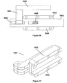
- the slam latch 1001 comprises a mounting body 1002, a latch bolt 1003, a handle, 1004, a latch bolt positioner 1005 and a keeper 1006.
- the mounting body 1002 comprises a mounting support 1021 and a mounting cover 1022.
- the sides 1023, 1024 of the mounting support project to define a channel/passageway for accommodating a cuboid latch bolt 1003.
- the cover 1022 may be fastened to the mounting support 1021 by way of fasteners (screws) 1025.
- fasteners (screws) 1025 When the mounting cover 1022 is fastened to the mounting support 1021, a channel/passageway is defined within which the bolt 1003 is held in a single plane.
- the mounting support 1021 has openings 1026, 1027 (see figure 19 ) through which fasteners (screws) extend to mount the mounting support 1021 to a gate (for example).
- the slam latch 1001 is shown mounted to a part of a post assembly 1007.
- the latch bolt 1003 has a longitudinal axis and is made of steel.
- the latch bolt is accommodated within the passageway/channel formed by the mounting support 1021 and the mounting cover 1022.
- the latch bolt 1003 is of cuboid overall shape, and it includes a number of cut-outs/slots.
- the latch bolt illustrated in these examples is "A" shaped, wherein the apex of the "A" is the keeper-engaging end 1031.
- the keeper-engaging end 1031 in these examples has a taper on one side 1032, which has an angle of about 4 to 8 degrees relative to the longitudinal axis and a length between about 3-12 mm (relative to the longitudinal axis).
- the latch bolt positioner 1005 comprises a latch bolt actuator 1051 (cam) pivotally mounted to the mounting support 1021 by way of a pivot bolt 1028. When assembled, the latch bolt actuator 1051 extends through a slot (cut-out) 1033 in the latch bolt.
- the latch bolt positioner 1005 further comprises a cam follower (roller) 1052 and a fastener (bolt) 1053.
- the cam follower 1052 is mounted on the bolt 1053.
- the cam follower 1052 is preferably made of nylon (which provides noise reduction compared to, for example, a steel cam follower).
- the latch bolt 1003 further comprises a slot 1034 for housing a biasing mechanism 1054, which comprises a helical spring 1055 and stop pin 1056.
- a biasing mechanism 1054 which comprises a helical spring 1055 and stop pin 1056.
- One end of the spring 1055 bears against the stop pin 1056, and the other bears against the side of the slot 1034.
- Actuation of the latch bolt actuator 1051 results in movement of the latch bolt 1003 into the unlocking position and compression of spring 1055, biasing the latch bolt 1003 to return to the locking position.
- the handle 1004 in the example illustrated in figures 10-22 is substantially linear, and is connected to the latch bolt actuator 1051.
- the handle is substantially L-shaped, including parts 1041 and 1042.
- the keeper 1006 has a steel body 1060 providing a blind opening 1061 for snugly receiving the keeper-engaging end 1031 of the latch bolt.
- the keeper body 1060 has a base 1062 and a pair of spaced walls 1063, 1064 that extend from the base 1062, all of which define the blind opening 1061 (and rear end of the walls).
- the spaced walls 1063 and 1064 together define a mouth of the opening 1066.
- the spaced wall 1064 extends towards wall 1063 as it nears the base 1062 so as to provide a snug fit for the keeper-retaining end 1031.
- One of the walls 1063 i.e.
- the front or leading wall has a sloping or ramped outer surface 1065 along which the keeper-engaging end 31 slides when on its way to the blind opening 1061 in the keeper 1006.
- the other wall 1064 i.e. the rear or trailing wall
- wall 1063 is approximately 4 mm longer than wall 1063.
- the base 1062 has openings (not shown) through which fasteners extend to mount the base 1062 to a fixture such as a post, jamb, framework or other structure.
- the mounting body 1002 is mounted to a hinged gate (or other type of movable panel) and the keeper 1006 is mounted to a non-moving fixture such as a gate post, jamb, framework or other structure.
- the latch bolt 1003 rides along and up over the sloping or ramped outer surface 1065 of the keeper 1006, and the spring 1055 ensures that the keeper-retaining end 1031 of the latch bolt 1003 engages the opening 1061 so as to lock the hinged gate to the gate post.
- the handle 1004 is levered by an operator away from the mounting body 1002, such that (cam) latch bolt actuator 1051 moves against cam follower 1052 so as to move the latch bolt 1003 into the unlocking position (this is illustrated in figure 22 ).
- the spring 1055 ensures that the latch bolt 1003 is again extended to the locking position.
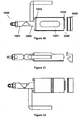
- Figures 28-35 illustrate a further example slam latch not according to the invention for locking a hinged gate (not shown) to a gate post (not shown), for example.
- the slam latch as described herein is particularly suited for securing doors and swinging panels, particularly in agricultural applications (eg. for handling livestock such as sheep, pigs or cattle), it may have other non-agricultural commercial uses.
- the slam latch 1100 comprises a mounting body 1200, a latch bolt 1300, a handle 1400, a latch bolt positioner 1500 and a keeper 1600.
- the mounting body 1200 comprises a mounting support 1221 and a mounting cover 1222.
- the mounting support 1221 defines a passageway/channel for accommodating a latch bolt 1300, which is of cuboid shape.
- the passageway is machined out of a solid piece of metal. This arrangement allows the mounting support 1221 to hold the latch bolt 1300 in a single plane, leading to a more robust and sturdy latch.
- the mounting support 1221 has openings (not shown) through which fasteners (screws) extend to mount the mounting plate 20 to a hinged gate.
- the latch bolt 1300 has a longitudinal axis and is made of steel.
- the latch bolt 1300 is accommodated within the mounting support 1221 for axial movement relative to the mounting body 1200 between a locking position (see figures 33 to 35 ) and an unlocking position (as shown in figures 28 to 32 ).
- the latch bolt 1300 comprises a cylindrical shaft region 1335 and a keeper-engaging end 1331 extending from the shaft region 1335.
- the keeper-engaging end 1331 is in the form of a plate and has a chamfered/tapered edge 1332 having an angle of about 4 to 8 degrees relative to the longitudinal axis and a length between about 3-12 mm (relative to the longitudinal axis).
- the handle 1400 is substantially L-shaped and is made of steel.
- One part 1441 of the handle 1400 extends substantially perpendicularly of the latch bolt 1300 shaft region 1335 and a free end 1442 of the handle 1400 extends substantially parallel with the longitudinal axis.
- the latch bolt positioner 1500 comprises a cam 1550, a cam follower 1551 and a biasing member (not shown - the biasing member is inside the mounting support 1221 in a similar arrangement to that shown in figures 10-26 ), and the cam 1550 and cam follower 1551 are made of steel.
- the biasing member is made of sprung steel.
- the biasing member is a spring that ensures that the cam 1550 and cam follower 1551 are always kept in contact with one another as well as that the latch bolt 1300 may return to the locking position when the handle is released by an operator.
- the cam 1550 is in the form of a collar extending around the shaft region 1335 of the latch bolt, and the handle 1400 is connected to the cam 1550 such that the cam 1550 may be rotated about the shaft region 1335 (longitudinal axis).
- the cam 1550 is a truncated cylinder/cylindrical wedge which bears against the cam follower 1551.
- the cam follower 1551 is in the form of a collar extending around and affixed to the shaft region 1335 of the latch bolt. Like the cam 1550, the cam follower 1551 is also a truncated cylinder/cylindrical wedge which bears against the cam 1550.
- the slam latch also includes a latch bolt adjuster 1800 for adjusting the throw of the bolt.
- the latch bolt adjuster 1800 comprises a nut 1880 which is positioned on a threaded end of the shaft region 1335 of the latch bolt 1300.
- the adjuster 1800 may comprise both the nut 1880 and thread. Turning the nut further onto the bolt reduces the throw, and turning the nut off the bolt increases the throw. Movement of the latch bolt adjuster 1800 may also advantageously adjust the tension of the biasing member, and may also alter the tolerances between the cam 1550 and cam follower 1551 to improve operation of the latch.
- the keeper 1600 has a steel body 1660 providing a blind opening 1661 for snugly receiving the keeper-engaging end 1331 of the latch bolt.
- the keeper body 1660 has a base 1662 and a pair of spaced walls 1663, 1664 that extend from the base 1662, all of which define the blind opening 1661.
- the spaced walls 1663, 1664 have inner faces that converge/extend towards one another as they near the base 1662 so as to provide a snug fit for the keeper-retaining end 1331.
- One of the walls 1663 ie. the front or leading wall
- the other wall 1664 ie. the rear or trailing wall
- the other wall 1664 is approximately 4 mm longer than wall 1663.
- the base 1662 has openings (not shown) through which fasteners extend to mount the base 1662 to a non-moving fixture such as a post, jamb, framework or other structure.
- the mounting body 1200 is mounted to a hinged gate (or other type of movable panel) and the keeper 1600 is mounted to a non-moving fixture such as a gate post, jamb, framework or other structure.
- a hinged gate or other type of movable panel
- the keeper 1600 is mounted to a non-moving fixture such as a gate post, jamb, framework or other structure.
- the reverse arrangement may also be used, such as when the mounting body is mounted to a non-moving fixture and the keeper 1600 is mounted to a moving fixture.
- the latch bolt 1300 rides along and up over the sloping or ramped outer surface 1665 of the keeper 1600, and the biasing member ensures that the keeper-retaining end 1331 of the latch bolt 1300 engages the opening 1661 so as to lock the hinged gate to the gate post.
- the handle 1400 is rotated by an operator such that the cam 1550 and cam follower 1551 are axially separated, and the keeper-engaging end 1331 disengages the keeper 1600.
- the biasing member ensures that the latch bolt 1300 is again extended to the locking position.
- the slam latch as exemplified is particularly suited for use in agriculture, such as for securing doors and swinging panels when constraining and limiting the movement of animals in pens yards and enclosed spaces such as cattle crushes.
- the slam latch as exemplified provides means for preventing a slam latch bolt from rattling against its associated receiving keeper when in the locking position.
- the slam latch as exemplified provides means to ensure the tight engagement of a door with its associated stop/keeper.
- the slam latch as exemplified also provides means to prevent the latch bolt travelling past the designated stop position.
- the slam latch as exemplified further provides means for obviating the necessity of accurately positioning a latch strike with respect to a door stop and yet retaining the desirable characteristics of accurate and careful installation of a door latch assembly.
- the inventors have found that having large chamfered ends/angles on round keeper-engaging ends of latch bolts increase the potential for such ends to disengage their keepers when subjected to excessive side force.
- the inventors have further found that having too little an angle (ie. 3 degrees or smaller) results in the end actually wanting to "lock” in a mating taper of the keeper (ie. morse-type tapers).
- the inventors have discovered that the optimal angle, on either the round ends (as per figures 3-7 ) or the flat keeper-engaging ends (as per figures 1 and 2 ), is usually anywhere between 4 degrees and 15 degrees (or even up to 20 degrees), so as to provide an optimal locking result.
- slam latches have a small chamfer, perhaps 1.5 - 3mm in length as measured from the end of the latch bolt along its axis, and this is to remove any sharp edge so as to limit the scraping of a sharp edge against the keeper/striker plate surface and assist the latch bolt to slide up on the keeper/striker plate and also assist in the engagement process - by helping the round latch bolt to begin to enter into the opening in the keeper/striker plate as early as possible.
- the chamfer is too big the door may swing past the opening and fail to engage. This is due to the speed of the door and the size / length of the chamfered edge - normally at 45 degrees, maximum 3mm in length.
- the chamfer is too big it will allow the leading edge of the latch bolt to begin to engage in the keeping region earlier but before the outside surface of the latch bolt diameter may propel outwards past the square edge of the keeper/striker plate opening so as to secure the latch bolt and halt the momentum - the chamfer may begin to make contact with the back edge (ie. rear wall/trailing wall) of the keeper/striker plate and actually begin to ride up over the back edge (ie. rear wall/trailing wall) of the opening forcing the latch bolt open again - due to the momentum and speed and 45 degree angle and depth of the chamfer.
- the present invention as exemplified in one or more examples on the other hand has a much longer chamfer (typically more than 3mm and preferably 8-10mm) and also a reduced angle (typically 4-15 degrees) to increase the positive engagement and reduce the risk of the latch bolt "riding up" the back edge (ie. rear wall/trailing wall).
- the back edge (rear wall/trailing wall) of the keeper/striker of the present invention is not on the same plane as the front edge (front or leading wall).
- the back edge (rear wall/trailing wall) projects out an extra 4mm or so which increases positive engagement of the latch bolt with the opening.
- the latch bolt strikes the front edge (front or leading wall) of the keeper/striker plate it causes the latch bolt to compress to a maximum of say 20mm.
- the keeper-engaging end of the latch bolt does not come into contact with the base of the keeper body or fixture to which the keeper body is mounted because the latch bolt is spring-loaded and, in agricultural situations, as an animal tries to move the panel or gate the spring/biasing member ensures that the latch bolt continues to move outwards until it is wedged between the inner faces of the walls thereby ensuring zero gap.
- the inventors have found this feature to be an important difference and advantage over known slam latches.
Landscapes
- Engineering & Computer Science (AREA)
- Mechanical Engineering (AREA)
- Gates (AREA)
- Lock And Its Accessories (AREA)
- Hinges (AREA)
Claims (15)
- Serrure à ressort (1001) comprenant :un corps de montage (1002) ;un pêne à ressort (1003) possédant un axe longitudinal et monté par rapport au corps de montage (1002) pour un mouvement axial par rapport au corps de montage (1002) entre une position de verrouillage et une position de déverrouillage, ledit pêne à ressort (1003) possédant une zone de mise en prise avec une gâche s'étendant à partir du corps de montage (1002) et se terminant au niveau d'une extrémité de mise en prise avec une gâche (1031) ;un positionneur de pêne à ressort (1005) comprenant un mécanisme de sollicitation (1054) pour solliciter le pêne à ressort (1003) vers la position de verrouillage ; etune gâche (1006) possédant au moins une paroi avant (1063) et une paroi arrière (1064) qui sont espacées pour définir une ouverture (1061) destinée à recevoir la zone de mise en prise avec une gâche, lesdites parois avant et arrière (1063, 1064) étant adaptées pour se mettre en prise avec la zone de mise en prise avec une gâche du pêne à ressort (1003) lorsque le pêne à ressort (1003) est dans la position de verrouillage ;ladite zone de mise en prise avec une gâche de pêne à ressort (1003) comprenant un côté de frappe (1032) contre une gâche qui frappe en premier la paroi avant (1063) de gâche tandis que la serrure (1001) est fermée, et ledit côté de frappe (1032) contre une gâche comprenant un biseau se rétrécissant vers l'extrémité de mise en prise (1031) avec une gâche ;caractérisé en ce que lorsque la serrure (1001) se ferme :(i) la paroi arrière (1064) de la gâche est inclinée de façon à venir en prise avec le biseau ; et(ii) le mécanisme de sollicitation (1054) entraînant la zone de mise en prise avec une gâche du pêne à ressort (1003) en prise avec la paroi avant (1063) de gâche et la paroi arrière (1064) de gâche ;pour minimiser ou éliminer ainsi le claquement de la serrure (1001) ;un côté de la zone de mise en prise avec une gâche de pêne à ressort opposé au côté de frappe contre une gâche étant plan, et la paroi avant (1063) de gâche qui vient en prise avec ledit côté de la zone de mise en prise avec une gâche de pêne à ressort opposé au côté de frappe contre une gâche étant plane ; et ladite paroi avant de la gâche (1063) présentant une surface externe inclinée ou en rampe (1065) le long de laquelle le côté de frappe (1032) contre une gâche de pêne à ressort coulisse lors du déplacement vers l'ouverture (1061) de gâche, et ladite paroi arrière de gâche (1064) faisant saillie au-delà de la paroi avant (1063) pour empêcher le pêne à ressort (1003) de passer au-delà ou de ne pas se mettre en prise avec l'ouverture (1061) tandis que la serrure (1001) est fermée.
- Serrure à ressort (1001) selon la revendication 1, ledit côté de frappe (1032) contre une gâche de pêne à ressort étant effilé selon un angle d'environ 4 à 20 degrés par rapport à l'axe longitudinal, de préférence selon un angle d'environ 4 à 15 degrés par rapport à l'axe longitudinal.
- Serrure à ressort (1001) selon la revendication 1 ou 2, ledit côté de frappe (1032) contre une gâche de pêne à ressort étant effilé sur environ 3 à 12 mm, tel que mesuré le long de l'axe longitudinal à partir de l'extrémité de mise en prise avec une gâche.
- Serrure à ressort (1001) selon l'une quelconque des revendications 1 à 3, ladite paroi arrière (1064) de gâche étant inclinée d'environ 4 à 20 degrés par rapport à l'axe longitudinal du pêne à ressort (1003), de préférence d'environ 4 à 15 degrés par rapport à l'axe longitudinal du pêne à ressort (1003).
- Serrure à ressort (1001) selon l'une quelconque des revendications 1 à 4, ladite zone de mise en prise avec une gâche étant effilée sur uniquement un côté longitudinal.
- Serrure à ressort (1001) selon l'une quelconque des revendications 1 à 5, lesdites parois avant et arrière de la gâche (1063, 1064) étant orientées pour épouser la forme de la zone de mise en prise avec une gâche.
- Serrure à ressort (1001) selon l'une quelconque des revendications 1 à 6, comprenant en outre : une poignée (1004) ; et
ledit positionneur (1005) de pêne à ressort servant à déplacer le pêne à ressort (1003) entre la position de verrouillage et la position de déverrouillage, le positionneur (1005) de pêne à ressort étant raccordé de manière fonctionnelle au pêne à ressort (1003) et à la poignée (1004), et le positionneur (1005) de pêne à ressort comprenant une came (1051) et un galet de came (1052) afin que le pêne à ressort (1003) se déplace entre la position de verrouillage et la position de déverrouillage tandis que la came (1051) est en appui contre le suiveur de came (1052). - Serrure à ressort (1001) selon la revendication 7, ladite came (1051) étant raccordée à la poignée (1004) et ledit galet de came (1052) étant raccordé au pêne à ressort (1003).
- Serrure à ressort (1001) selon la revendication 8, ladite came se présentant sous la forme d'un actionneur (1051) de pêne à ressort raccordé de manière pivotante au corps de montage (1002), et ledit galet de came se présentant sous la forme d'une roue cylindrique (1052) goupillée au pêne à ressort (1003).
- Serrure à ressort (1001) selon l'une quelconque des revendications 7 à 9, ledit pêne à ressort (1003) comprenant une fente (1033) et ledit galet de came (1052) étant positionné à l'intérieur de la fente (1033).
- Serrure à ressort (1001) selon l'une quelconque des revendications 7 à 10, ledit pêne à ressort (1003) comprenant une fente (1034) et ledit mécanisme de sollicitation (1054) étant positionné à l'intérieur de la fente (1034).
- Serrure à ressort (1001) selon l'une quelconque des revendications 1 à 11, ledit pêne à ressort (1003) possédant une forme cuboïde.
- Serrure à ressort (1001) selon l'une quelconque des revendications 1 à 12, ladite zone de mise en prise avec la gâche du pêne à ressort possédant une forme cylindrique.
- Serrure à ressort (1001) selon l'une quelconque des revendications 1 à 13, ladite gâche (1006) comprenant une base (1062) s'étendant entre les parois arrière et avant (1063, 1064), et lorsque la serrure (1001) est fermée, ladite extrémité de mise en prise avec une gâche du pêne à ressort n'entrant pas en contact avec la base (1062).
- Serrure à ressort (1001) selon l'une quelconque des revendications 1 à 14, ladite serrure (1001) étant destinée à être utilisée dans la gestion de bovins, de porcs ou de moutons.
Applications Claiming Priority (2)
| Application Number | Priority Date | Filing Date | Title |
|---|---|---|---|
| AU2012902339A AU2012902339A0 (en) | 2012-06-05 | Slam Latch | |
| PCT/AU2013/000577 WO2013181688A1 (fr) | 2012-06-05 | 2013-05-31 | Serrure à ressort |
Publications (3)
| Publication Number | Publication Date |
|---|---|
| EP2855808A1 EP2855808A1 (fr) | 2015-04-08 |
| EP2855808A4 EP2855808A4 (fr) | 2015-12-23 |
| EP2855808B1 true EP2855808B1 (fr) | 2020-09-23 |
Family
ID=49711192
Family Applications (1)
| Application Number | Title | Priority Date | Filing Date |
|---|---|---|---|
| EP13800833.9A Active EP2855808B1 (fr) | 2012-06-05 | 2013-05-31 | Serrure à ressort |
Country Status (5)
| Country | Link |
|---|---|
| US (2) | US20150084347A1 (fr) |
| EP (1) | EP2855808B1 (fr) |
| CA (1) | CA2913648C (fr) |
| NZ (1) | NZ630112A (fr) |
| WO (1) | WO2013181688A1 (fr) |
Families Citing this family (13)
| Publication number | Priority date | Publication date | Assignee | Title |
|---|---|---|---|---|
| US9410348B1 (en) | 2014-01-04 | 2016-08-09 | Carlson Pet Products, Inc. | Latch apparatus |
| US20150192304A1 (en) * | 2014-01-06 | 2015-07-09 | General Electric Company | Oven appliance |
| US9388603B2 (en) | 2014-03-13 | 2016-07-12 | Carlson Pet Products, Inc. | Hands free gate |
| US9821957B1 (en) * | 2015-08-18 | 2017-11-21 | David Robert Hurst | Locking apparatus for a refuse container lid |
| US10407965B2 (en) | 2016-12-22 | 2019-09-10 | Universal City Studios Llc | Cam locking shotgun gate |
| US10378255B2 (en) * | 2017-08-28 | 2019-08-13 | Taiwan Cable Industrial Co, Ltd. | Animal crate latch |
| US10966522B2 (en) | 2019-07-18 | 2021-04-06 | International Business Machines Corporation | Drawer latching assembly |
| AU2019283805B1 (en) * | 2019-12-17 | 2021-03-04 | Assa Abloy New Zealand Limited | Lock assembly |
| US11746566B2 (en) * | 2020-05-19 | 2023-09-05 | Jacob Adamosky | Ladder latch |
| DE102020115567A1 (de) * | 2020-06-12 | 2021-12-16 | Recaro Aircraft Seating Gmbh & Co. Kg | Flugzeugsitzmodul |
| US12139943B2 (en) * | 2020-12-03 | 2024-11-12 | MATEC Property Group, LLC | Hands free bathroom stall latch |
| US11785367B2 (en) * | 2021-05-19 | 2023-10-10 | Biamp Systems, LLC | Speaker mount with spring-loaded latch |
| US20250347303A1 (en) * | 2024-05-08 | 2025-11-13 | Hanwit Precision Industries Ltd. | Fixing device |
Citations (4)
| Publication number | Priority date | Publication date | Assignee | Title |
|---|---|---|---|---|
| US2759752A (en) * | 1955-02-04 | 1956-08-21 | Alva R Demings | Gate latch unit |
| US3955837A (en) * | 1975-01-20 | 1976-05-11 | Christensen Lars N | Latch |
| FR2897632A1 (fr) * | 2006-02-20 | 2007-08-24 | Guy Vattier | Verrou pour portes de boxes de chevaux |
| DE202007013833U1 (de) * | 2007-12-12 | 2008-03-27 | Akom Gmbh Spritzgusstechnik | Selbstschließender Tür- und Torverschluss für Weidebetrieb |
Family Cites Families (14)
| Publication number | Priority date | Publication date | Assignee | Title |
|---|---|---|---|---|
| GB1095541A (fr) * | ||||
| US1318988A (en) * | 1919-10-14 | Doobradjttsteb | ||
| GB165139A (en) * | 1920-02-11 | 1921-06-13 | Niels Nielsen Ladefoged | Improvements in or relating to fastenings or locks for doors and the like |
| US1419230A (en) | 1920-05-08 | 1922-06-13 | Crompton Edwin | Latch |
| US1604540A (en) * | 1926-01-18 | 1926-10-26 | S W Taggart | Door latch |
| US2542130A (en) * | 1947-06-17 | 1951-02-20 | Carl F Friend | Lock set for doors |
| US2810824A (en) * | 1954-09-21 | 1957-10-22 | Kaufman Paul | Lamp fixture light globe support |
| US2781215A (en) * | 1955-05-05 | 1957-02-12 | Joseph R Griffith | Bolt lock |
| US3984136A (en) * | 1975-10-01 | 1976-10-05 | Bills Marius W | Lock for sliding doors |
| US5887928A (en) * | 1995-11-07 | 1999-03-30 | Featherlite Mfg., Inc. | Slam latch for horse trailer |
| AU2002340278A1 (en) * | 2001-11-02 | 2003-05-19 | The Holland Group, Inc. | Industrial e-hitch trailer coupler |
| US20040251694A1 (en) * | 2003-06-13 | 2004-12-16 | Dennis Gorski | Gate latch mechanism |
| US7878558B1 (en) * | 2006-10-26 | 2011-02-01 | William Russell Bell | Gate latch |
| DE202010008334U1 (de) * | 2010-08-23 | 2010-10-28 | Baugruppentechnik Pollmeier Gmbh | Schließblech für eine Türzarge |
-
2013
- 2013-05-31 WO PCT/AU2013/000577 patent/WO2013181688A1/fr not_active Ceased
- 2013-05-31 CA CA2913648A patent/CA2913648C/fr active Active
- 2013-05-31 NZ NZ630112A patent/NZ630112A/en unknown
- 2013-05-31 EP EP13800833.9A patent/EP2855808B1/fr active Active
-
2014
- 2014-12-04 US US14/560,918 patent/US20150084347A1/en not_active Abandoned
- 2014-12-05 US US14/561,791 patent/US9758996B2/en active Active
Patent Citations (4)
| Publication number | Priority date | Publication date | Assignee | Title |
|---|---|---|---|---|
| US2759752A (en) * | 1955-02-04 | 1956-08-21 | Alva R Demings | Gate latch unit |
| US3955837A (en) * | 1975-01-20 | 1976-05-11 | Christensen Lars N | Latch |
| FR2897632A1 (fr) * | 2006-02-20 | 2007-08-24 | Guy Vattier | Verrou pour portes de boxes de chevaux |
| DE202007013833U1 (de) * | 2007-12-12 | 2008-03-27 | Akom Gmbh Spritzgusstechnik | Selbstschließender Tür- und Torverschluss für Weidebetrieb |
Also Published As
| Publication number | Publication date |
|---|---|
| CA2913648C (fr) | 2020-07-07 |
| NZ630112A (en) | 2015-07-31 |
| CA2913648A1 (fr) | 2013-12-12 |
| EP2855808A4 (fr) | 2015-12-23 |
| EP2855808A1 (fr) | 2015-04-08 |
| WO2013181688A1 (fr) | 2013-12-12 |
| US20150084347A1 (en) | 2015-03-26 |
| US9758996B2 (en) | 2017-09-12 |
| US20150115623A1 (en) | 2015-04-30 |
Similar Documents
| Publication | Publication Date | Title |
|---|---|---|
| EP2855808B1 (fr) | Serrure à ressort | |
| US12098575B2 (en) | Transverse concealed latch system | |
| US20130098124A1 (en) | Rotary latch | |
| US6615449B1 (en) | Releasable locking assembly for a door control cylinder | |
| GB2294722A (en) | Deadlock and latch with remote lock operator | |
| AU2014277838B2 (en) | Latch | |
| US5024472A (en) | Flushbolt actuator assembly | |
| CA2875425C (fr) | Dispositif de verrouillage multipoint | |
| US8403381B2 (en) | Horse stall door latch | |
| US3437363A (en) | Sliding patio door lock assembly | |
| DE8704036U1 (de) | Türschloß mit Verriegelungselement und Hilfsfalle | |
| US3808850A (en) | Locking handle assembly | |
| US11746566B2 (en) | Ladder latch | |
| US11781346B2 (en) | Latch structure | |
| GB2151293A (en) | Locking system | |
| GB2423787A (en) | Bi-directional bolt-restraint mechanism | |
| NL2007662C2 (en) | Lock assembly with a bolt. | |
| US20250369267A1 (en) | Remote lock assembly for use with a multipoint lock system | |
| EP3199740B1 (fr) | Dispositif d'étanchéité comprenant une barre d'étanchéité mobile | |
| DE202015004372U1 (de) | Endlageeinzugs- und Endlagedämpfungsvorrichtung für einen an einem Rahmen drehbar gelagerten Flügel eines Fensters oder einer Tür | |
| US20260035972A1 (en) | Improvements to latches for movable barriers or the like | |
| JPH03191187A (ja) | ラッチ装置 | |
| GB1600854A (en) | Latches | |
| CA2445657C (fr) | Dispositif de verrouillage ameliore | |
| WO2015188236A1 (fr) | Serrure à pêne dormant multipoint haute sécurité |
Legal Events
| Date | Code | Title | Description |
|---|---|---|---|
| PUAI | Public reference made under article 153(3) epc to a published international application that has entered the european phase |
Free format text: ORIGINAL CODE: 0009012 |
|
| 17P | Request for examination filed |
Effective date: 20141230 |
|
| AK | Designated contracting states |
Kind code of ref document: A1 Designated state(s): AL AT BE BG CH CY CZ DE DK EE ES FI FR GB GR HR HU IE IS IT LI LT LU LV MC MK MT NL NO PL PT RO RS SE SI SK SM TR |
|
| AX | Request for extension of the european patent |
Extension state: BA ME |
|
| DAX | Request for extension of the european patent (deleted) | ||
| RA4 | Supplementary search report drawn up and despatched (corrected) |
Effective date: 20151120 |
|
| RIC1 | Information provided on ipc code assigned before grant |
Ipc: E05C 19/02 20060101ALI20151116BHEP Ipc: E06B 11/06 20060101ALI20151116BHEP Ipc: E05C 1/08 20060101AFI20151116BHEP Ipc: E05B 17/00 20060101ALI20151116BHEP |
|
| STAA | Information on the status of an ep patent application or granted ep patent |
Free format text: STATUS: EXAMINATION IS IN PROGRESS |
|
| 17Q | First examination report despatched |
Effective date: 20180612 |
|
| GRAP | Despatch of communication of intention to grant a patent |
Free format text: ORIGINAL CODE: EPIDOSNIGR1 |
|
| STAA | Information on the status of an ep patent application or granted ep patent |
Free format text: STATUS: GRANT OF PATENT IS INTENDED |
|
| INTG | Intention to grant announced |
Effective date: 20200504 |
|
| GRAS | Grant fee paid |
Free format text: ORIGINAL CODE: EPIDOSNIGR3 |
|
| GRAA | (expected) grant |
Free format text: ORIGINAL CODE: 0009210 |
|
| STAA | Information on the status of an ep patent application or granted ep patent |
Free format text: STATUS: THE PATENT HAS BEEN GRANTED |
|
| RAP1 | Party data changed (applicant data changed or rights of an application transferred) |
Owner name: TRETHEWEY, REGINALD Owner name: CLIPEX IP LIMITED |
|
| RIN1 | Information on inventor provided before grant (corrected) |
Inventor name: OLSSON, STAFFORD JAMES Inventor name: OLSSON, ASHLEY DEAN Inventor name: OLSSON, NATHANAEL DEAN Inventor name: OLSSON, ASHLEY NORMAN Inventor name: TRETHEWEY, REGINALD Inventor name: OLSSON, KIERAN BLAKE |
|
| AK | Designated contracting states |
Kind code of ref document: B1 Designated state(s): AL AT BE BG CH CY CZ DE DK EE ES FI FR GB GR HR HU IE IS IT LI LT LU LV MC MK MT NL NO PL PT RO RS SE SI SK SM TR |
|
| REG | Reference to a national code |
Ref country code: GB Ref legal event code: FG4D |
|
| REG | Reference to a national code |
Ref country code: CH Ref legal event code: EP |
|
| REG | Reference to a national code |
Ref country code: IE Ref legal event code: FG4D |
|
| REG | Reference to a national code |
Ref country code: DE Ref legal event code: R096 Ref document number: 602013072788 Country of ref document: DE Ref country code: AT Ref legal event code: REF Ref document number: 1316527 Country of ref document: AT Kind code of ref document: T Effective date: 20201015 |
|
| PG25 | Lapsed in a contracting state [announced via postgrant information from national office to epo] |
Ref country code: FI Free format text: LAPSE BECAUSE OF FAILURE TO SUBMIT A TRANSLATION OF THE DESCRIPTION OR TO PAY THE FEE WITHIN THE PRESCRIBED TIME-LIMIT Effective date: 20200923 Ref country code: BG Free format text: LAPSE BECAUSE OF FAILURE TO SUBMIT A TRANSLATION OF THE DESCRIPTION OR TO PAY THE FEE WITHIN THE PRESCRIBED TIME-LIMIT Effective date: 20201223 Ref country code: NO Free format text: LAPSE BECAUSE OF FAILURE TO SUBMIT A TRANSLATION OF THE DESCRIPTION OR TO PAY THE FEE WITHIN THE PRESCRIBED TIME-LIMIT Effective date: 20201223 Ref country code: GR Free format text: LAPSE BECAUSE OF FAILURE TO SUBMIT A TRANSLATION OF THE DESCRIPTION OR TO PAY THE FEE WITHIN THE PRESCRIBED TIME-LIMIT Effective date: 20201224 Ref country code: SE Free format text: LAPSE BECAUSE OF FAILURE TO SUBMIT A TRANSLATION OF THE DESCRIPTION OR TO PAY THE FEE WITHIN THE PRESCRIBED TIME-LIMIT Effective date: 20200923 Ref country code: HR Free format text: LAPSE BECAUSE OF FAILURE TO SUBMIT A TRANSLATION OF THE DESCRIPTION OR TO PAY THE FEE WITHIN THE PRESCRIBED TIME-LIMIT Effective date: 20200923 |
|
| REG | Reference to a national code |
Ref country code: AT Ref legal event code: MK05 Ref document number: 1316527 Country of ref document: AT Kind code of ref document: T Effective date: 20200923 |
|
| PG25 | Lapsed in a contracting state [announced via postgrant information from national office to epo] |
Ref country code: RS Free format text: LAPSE BECAUSE OF FAILURE TO SUBMIT A TRANSLATION OF THE DESCRIPTION OR TO PAY THE FEE WITHIN THE PRESCRIBED TIME-LIMIT Effective date: 20200923 Ref country code: LV Free format text: LAPSE BECAUSE OF FAILURE TO SUBMIT A TRANSLATION OF THE DESCRIPTION OR TO PAY THE FEE WITHIN THE PRESCRIBED TIME-LIMIT Effective date: 20200923 |
|
| REG | Reference to a national code |
Ref country code: NL Ref legal event code: MP Effective date: 20200923 |
|
| REG | Reference to a national code |
Ref country code: LT Ref legal event code: MG4D |
|
| PG25 | Lapsed in a contracting state [announced via postgrant information from national office to epo] |
Ref country code: EE Free format text: LAPSE BECAUSE OF FAILURE TO SUBMIT A TRANSLATION OF THE DESCRIPTION OR TO PAY THE FEE WITHIN THE PRESCRIBED TIME-LIMIT Effective date: 20200923 Ref country code: CZ Free format text: LAPSE BECAUSE OF FAILURE TO SUBMIT A TRANSLATION OF THE DESCRIPTION OR TO PAY THE FEE WITHIN THE PRESCRIBED TIME-LIMIT Effective date: 20200923 Ref country code: SM Free format text: LAPSE BECAUSE OF FAILURE TO SUBMIT A TRANSLATION OF THE DESCRIPTION OR TO PAY THE FEE WITHIN THE PRESCRIBED TIME-LIMIT Effective date: 20200923 Ref country code: RO Free format text: LAPSE BECAUSE OF FAILURE TO SUBMIT A TRANSLATION OF THE DESCRIPTION OR TO PAY THE FEE WITHIN THE PRESCRIBED TIME-LIMIT Effective date: 20200923 Ref country code: NL Free format text: LAPSE BECAUSE OF FAILURE TO SUBMIT A TRANSLATION OF THE DESCRIPTION OR TO PAY THE FEE WITHIN THE PRESCRIBED TIME-LIMIT Effective date: 20200923 Ref country code: LT Free format text: LAPSE BECAUSE OF FAILURE TO SUBMIT A TRANSLATION OF THE DESCRIPTION OR TO PAY THE FEE WITHIN THE PRESCRIBED TIME-LIMIT Effective date: 20200923 Ref country code: PT Free format text: LAPSE BECAUSE OF FAILURE TO SUBMIT A TRANSLATION OF THE DESCRIPTION OR TO PAY THE FEE WITHIN THE PRESCRIBED TIME-LIMIT Effective date: 20210125 |
|
| PG25 | Lapsed in a contracting state [announced via postgrant information from national office to epo] |
Ref country code: AL Free format text: LAPSE BECAUSE OF FAILURE TO SUBMIT A TRANSLATION OF THE DESCRIPTION OR TO PAY THE FEE WITHIN THE PRESCRIBED TIME-LIMIT Effective date: 20200923 Ref country code: AT Free format text: LAPSE BECAUSE OF FAILURE TO SUBMIT A TRANSLATION OF THE DESCRIPTION OR TO PAY THE FEE WITHIN THE PRESCRIBED TIME-LIMIT Effective date: 20200923 Ref country code: ES Free format text: LAPSE BECAUSE OF FAILURE TO SUBMIT A TRANSLATION OF THE DESCRIPTION OR TO PAY THE FEE WITHIN THE PRESCRIBED TIME-LIMIT Effective date: 20200923 Ref country code: PL Free format text: LAPSE BECAUSE OF FAILURE TO SUBMIT A TRANSLATION OF THE DESCRIPTION OR TO PAY THE FEE WITHIN THE PRESCRIBED TIME-LIMIT Effective date: 20200923 Ref country code: IS Free format text: LAPSE BECAUSE OF FAILURE TO SUBMIT A TRANSLATION OF THE DESCRIPTION OR TO PAY THE FEE WITHIN THE PRESCRIBED TIME-LIMIT Effective date: 20210123 |
|
| REG | Reference to a national code |
Ref country code: DE Ref legal event code: R097 Ref document number: 602013072788 Country of ref document: DE |
|
| PG25 | Lapsed in a contracting state [announced via postgrant information from national office to epo] |
Ref country code: SK Free format text: LAPSE BECAUSE OF FAILURE TO SUBMIT A TRANSLATION OF THE DESCRIPTION OR TO PAY THE FEE WITHIN THE PRESCRIBED TIME-LIMIT Effective date: 20200923 |
|
| PLBE | No opposition filed within time limit |
Free format text: ORIGINAL CODE: 0009261 |
|
| STAA | Information on the status of an ep patent application or granted ep patent |
Free format text: STATUS: NO OPPOSITION FILED WITHIN TIME LIMIT |
|
| PG25 | Lapsed in a contracting state [announced via postgrant information from national office to epo] |
Ref country code: DK Free format text: LAPSE BECAUSE OF FAILURE TO SUBMIT A TRANSLATION OF THE DESCRIPTION OR TO PAY THE FEE WITHIN THE PRESCRIBED TIME-LIMIT Effective date: 20200923 Ref country code: SI Free format text: LAPSE BECAUSE OF FAILURE TO SUBMIT A TRANSLATION OF THE DESCRIPTION OR TO PAY THE FEE WITHIN THE PRESCRIBED TIME-LIMIT Effective date: 20200923 |
|
| 26N | No opposition filed |
Effective date: 20210624 |
|
| PG25 | Lapsed in a contracting state [announced via postgrant information from national office to epo] |
Ref country code: IT Free format text: LAPSE BECAUSE OF FAILURE TO SUBMIT A TRANSLATION OF THE DESCRIPTION OR TO PAY THE FEE WITHIN THE PRESCRIBED TIME-LIMIT Effective date: 20200923 |
|
| REG | Reference to a national code |
Ref country code: CH Ref legal event code: PL |
|
| PG25 | Lapsed in a contracting state [announced via postgrant information from national office to epo] |
Ref country code: CH Free format text: LAPSE BECAUSE OF NON-PAYMENT OF DUE FEES Effective date: 20210531 Ref country code: LI Free format text: LAPSE BECAUSE OF NON-PAYMENT OF DUE FEES Effective date: 20210531 Ref country code: MC Free format text: LAPSE BECAUSE OF FAILURE TO SUBMIT A TRANSLATION OF THE DESCRIPTION OR TO PAY THE FEE WITHIN THE PRESCRIBED TIME-LIMIT Effective date: 20200923 Ref country code: LU Free format text: LAPSE BECAUSE OF NON-PAYMENT OF DUE FEES Effective date: 20210531 |
|
| REG | Reference to a national code |
Ref country code: BE Ref legal event code: MM Effective date: 20210531 |
|
| PG25 | Lapsed in a contracting state [announced via postgrant information from national office to epo] |
Ref country code: BE Free format text: LAPSE BECAUSE OF NON-PAYMENT OF DUE FEES Effective date: 20210531 |
|
| PG25 | Lapsed in a contracting state [announced via postgrant information from national office to epo] |
Ref country code: HU Free format text: LAPSE BECAUSE OF FAILURE TO SUBMIT A TRANSLATION OF THE DESCRIPTION OR TO PAY THE FEE WITHIN THE PRESCRIBED TIME-LIMIT; INVALID AB INITIO Effective date: 20130531 |
|
| PG25 | Lapsed in a contracting state [announced via postgrant information from national office to epo] |
Ref country code: CY Free format text: LAPSE BECAUSE OF FAILURE TO SUBMIT A TRANSLATION OF THE DESCRIPTION OR TO PAY THE FEE WITHIN THE PRESCRIBED TIME-LIMIT Effective date: 20200923 |
|
| P01 | Opt-out of the competence of the unified patent court (upc) registered |
Effective date: 20230530 |
|
| PG25 | Lapsed in a contracting state [announced via postgrant information from national office to epo] |
Ref country code: MK Free format text: LAPSE BECAUSE OF FAILURE TO SUBMIT A TRANSLATION OF THE DESCRIPTION OR TO PAY THE FEE WITHIN THE PRESCRIBED TIME-LIMIT Effective date: 20200923 |
|
| PG25 | Lapsed in a contracting state [announced via postgrant information from national office to epo] |
Ref country code: MT Free format text: LAPSE BECAUSE OF FAILURE TO SUBMIT A TRANSLATION OF THE DESCRIPTION OR TO PAY THE FEE WITHIN THE PRESCRIBED TIME-LIMIT Effective date: 20200923 |
|
| PGFP | Annual fee paid to national office [announced via postgrant information from national office to epo] |
Ref country code: DE Payment date: 20250521 Year of fee payment: 13 |
|
| PGFP | Annual fee paid to national office [announced via postgrant information from national office to epo] |
Ref country code: GB Payment date: 20250521 Year of fee payment: 13 |
|
| PGFP | Annual fee paid to national office [announced via postgrant information from national office to epo] |
Ref country code: FR Payment date: 20250528 Year of fee payment: 13 |
|
| PGFP | Annual fee paid to national office [announced via postgrant information from national office to epo] |
Ref country code: IE Payment date: 20250521 Year of fee payment: 13 |
|
| PG25 | Lapsed in a contracting state [announced via postgrant information from national office to epo] |
Ref country code: TR Free format text: LAPSE BECAUSE OF FAILURE TO SUBMIT A TRANSLATION OF THE DESCRIPTION OR TO PAY THE FEE WITHIN THE PRESCRIBED TIME-LIMIT Effective date: 20200923 |