EP2855954B1 - Improved segmented bearing retainer - Google Patents
Improved segmented bearing retainer Download PDFInfo
- Publication number
- EP2855954B1 EP2855954B1 EP13714732.8A EP13714732A EP2855954B1 EP 2855954 B1 EP2855954 B1 EP 2855954B1 EP 13714732 A EP13714732 A EP 13714732A EP 2855954 B1 EP2855954 B1 EP 2855954B1
- Authority
- EP
- European Patent Office
- Prior art keywords
- spacer
- bridge
- ring
- rings
- bearing
- Prior art date
- Legal status (The legal status is an assumption and is not a legal conclusion. Google has not performed a legal analysis and makes no representation as to the accuracy of the status listed.)
- Active
Links
- 125000006850 spacer group Chemical group 0.000 claims description 88
- 238000005096 rolling process Methods 0.000 claims description 31
- 238000000034 method Methods 0.000 claims description 15
- 239000000463 material Substances 0.000 claims description 7
- 238000003466 welding Methods 0.000 claims description 5
- 239000012255 powdered metal Substances 0.000 claims description 4
- 230000008878 coupling Effects 0.000 claims description 2
- 238000010168 coupling process Methods 0.000 claims description 2
- 238000005859 coupling reaction Methods 0.000 claims description 2
- 238000009434 installation Methods 0.000 claims description 2
- 230000008021 deposition Effects 0.000 claims 1
- 239000000314 lubricant Substances 0.000 description 13
- 230000014759 maintenance of location Effects 0.000 description 9
- 238000005304 joining Methods 0.000 description 7
- 238000010276 construction Methods 0.000 description 6
- 239000004696 Poly ether ether ketone Substances 0.000 description 4
- 229920002530 polyetherether ketone Polymers 0.000 description 4
- 229920000642 polymer Polymers 0.000 description 4
- 229910000831 Steel Inorganic materials 0.000 description 3
- 238000003780 insertion Methods 0.000 description 3
- 230000037431 insertion Effects 0.000 description 3
- 239000010959 steel Substances 0.000 description 3
- 239000004519 grease Substances 0.000 description 2
- 238000005461 lubrication Methods 0.000 description 2
- 239000002184 metal Substances 0.000 description 2
- 229910052751 metal Inorganic materials 0.000 description 2
- 230000006978 adaptation Effects 0.000 description 1
- 239000000853 adhesive Substances 0.000 description 1
- 230000001070 adhesive effect Effects 0.000 description 1
- 230000009286 beneficial effect Effects 0.000 description 1
- 238000005520 cutting process Methods 0.000 description 1
- 238000005242 forging Methods 0.000 description 1
- 238000005470 impregnation Methods 0.000 description 1
- 230000001050 lubricating effect Effects 0.000 description 1
- 238000003754 machining Methods 0.000 description 1
- 150000002739 metals Chemical class 0.000 description 1
- 238000009740 moulding (composite fabrication) Methods 0.000 description 1
- 229920000620 organic polymer Polymers 0.000 description 1
- 230000000135 prohibitive effect Effects 0.000 description 1
- 238000003860 storage Methods 0.000 description 1
- 229920001169 thermoplastic Polymers 0.000 description 1
- 239000004416 thermosoftening plastic Substances 0.000 description 1
- 239000012207 thread-locking agent Substances 0.000 description 1
Images



Classifications
-
- F—MECHANICAL ENGINEERING; LIGHTING; HEATING; WEAPONS; BLASTING
- F16—ENGINEERING ELEMENTS AND UNITS; GENERAL MEASURES FOR PRODUCING AND MAINTAINING EFFECTIVE FUNCTIONING OF MACHINES OR INSTALLATIONS; THERMAL INSULATION IN GENERAL
- F16C—SHAFTS; FLEXIBLE SHAFTS; ELEMENTS OR CRANKSHAFT MECHANISMS; ROTARY BODIES OTHER THAN GEARING ELEMENTS; BEARINGS
- F16C33/00—Parts of bearings; Special methods for making bearings or parts thereof
- F16C33/30—Parts of ball or roller bearings
- F16C33/46—Cages for rollers or needles
- F16C33/50—Cages for rollers or needles formed of interconnected members, e.g. chains
- F16C33/508—Cages for rollers or needles formed of interconnected members, e.g. chains formed of links having an H-shape, i.e. links with a single stay placed between two rollers and with two end portions extending along the end faces of the two rollers
-
- F—MECHANICAL ENGINEERING; LIGHTING; HEATING; WEAPONS; BLASTING
- F16—ENGINEERING ELEMENTS AND UNITS; GENERAL MEASURES FOR PRODUCING AND MAINTAINING EFFECTIVE FUNCTIONING OF MACHINES OR INSTALLATIONS; THERMAL INSULATION IN GENERAL
- F16C—SHAFTS; FLEXIBLE SHAFTS; ELEMENTS OR CRANKSHAFT MECHANISMS; ROTARY BODIES OTHER THAN GEARING ELEMENTS; BEARINGS
- F16C33/00—Parts of bearings; Special methods for making bearings or parts thereof
- F16C33/30—Parts of ball or roller bearings
- F16C33/46—Cages for rollers or needles
- F16C33/4611—Cages for rollers or needles with hybrid structure, i.e. with parts made of distinct materials
-
- F—MECHANICAL ENGINEERING; LIGHTING; HEATING; WEAPONS; BLASTING
- F16—ENGINEERING ELEMENTS AND UNITS; GENERAL MEASURES FOR PRODUCING AND MAINTAINING EFFECTIVE FUNCTIONING OF MACHINES OR INSTALLATIONS; THERMAL INSULATION IN GENERAL
- F16C—SHAFTS; FLEXIBLE SHAFTS; ELEMENTS OR CRANKSHAFT MECHANISMS; ROTARY BODIES OTHER THAN GEARING ELEMENTS; BEARINGS
- F16C43/00—Assembling bearings
- F16C43/04—Assembling rolling-contact bearings
-
- F—MECHANICAL ENGINEERING; LIGHTING; HEATING; WEAPONS; BLASTING
- F16—ENGINEERING ELEMENTS AND UNITS; GENERAL MEASURES FOR PRODUCING AND MAINTAINING EFFECTIVE FUNCTIONING OF MACHINES OR INSTALLATIONS; THERMAL INSULATION IN GENERAL
- F16C—SHAFTS; FLEXIBLE SHAFTS; ELEMENTS OR CRANKSHAFT MECHANISMS; ROTARY BODIES OTHER THAN GEARING ELEMENTS; BEARINGS
- F16C43/00—Assembling bearings
- F16C43/04—Assembling rolling-contact bearings
- F16C43/06—Placing rolling bodies in cages or bearings
- F16C43/065—Placing rolling bodies in cages or bearings in cages
-
- F—MECHANICAL ENGINEERING; LIGHTING; HEATING; WEAPONS; BLASTING
- F16—ENGINEERING ELEMENTS AND UNITS; GENERAL MEASURES FOR PRODUCING AND MAINTAINING EFFECTIVE FUNCTIONING OF MACHINES OR INSTALLATIONS; THERMAL INSULATION IN GENERAL
- F16C—SHAFTS; FLEXIBLE SHAFTS; ELEMENTS OR CRANKSHAFT MECHANISMS; ROTARY BODIES OTHER THAN GEARING ELEMENTS; BEARINGS
- F16C19/00—Bearings with rolling contact, for exclusively rotary movement
- F16C19/22—Bearings with rolling contact, for exclusively rotary movement with bearing rollers essentially of the same size in one or more circular rows, e.g. needle bearings
- F16C19/34—Bearings with rolling contact, for exclusively rotary movement with bearing rollers essentially of the same size in one or more circular rows, e.g. needle bearings for both radial and axial load
- F16C19/36—Bearings with rolling contact, for exclusively rotary movement with bearing rollers essentially of the same size in one or more circular rows, e.g. needle bearings for both radial and axial load with a single row of rollers
- F16C19/364—Bearings with rolling contact, for exclusively rotary movement with bearing rollers essentially of the same size in one or more circular rows, e.g. needle bearings for both radial and axial load with a single row of rollers with tapered rollers, i.e. rollers having essentially the shape of a truncated cone
-
- F—MECHANICAL ENGINEERING; LIGHTING; HEATING; WEAPONS; BLASTING
- F16—ENGINEERING ELEMENTS AND UNITS; GENERAL MEASURES FOR PRODUCING AND MAINTAINING EFFECTIVE FUNCTIONING OF MACHINES OR INSTALLATIONS; THERMAL INSULATION IN GENERAL
- F16C—SHAFTS; FLEXIBLE SHAFTS; ELEMENTS OR CRANKSHAFT MECHANISMS; ROTARY BODIES OTHER THAN GEARING ELEMENTS; BEARINGS
- F16C2300/00—Application independent of particular apparatuses
- F16C2300/10—Application independent of particular apparatuses related to size
- F16C2300/14—Large applications, e.g. bearings having an inner diameter exceeding 500 mm
-
- F—MECHANICAL ENGINEERING; LIGHTING; HEATING; WEAPONS; BLASTING
- F16—ENGINEERING ELEMENTS AND UNITS; GENERAL MEASURES FOR PRODUCING AND MAINTAINING EFFECTIVE FUNCTIONING OF MACHINES OR INSTALLATIONS; THERMAL INSULATION IN GENERAL
- F16C—SHAFTS; FLEXIBLE SHAFTS; ELEMENTS OR CRANKSHAFT MECHANISMS; ROTARY BODIES OTHER THAN GEARING ELEMENTS; BEARINGS
- F16C33/00—Parts of bearings; Special methods for making bearings or parts thereof
- F16C33/30—Parts of ball or roller bearings
- F16C33/46—Cages for rollers or needles
- F16C33/4617—Massive or moulded cages having cage pockets surrounding the rollers, e.g. machined window cages
- F16C33/4664—Massive or moulded cages having cage pockets surrounding the rollers, e.g. machined window cages with more than three parts, e.g. two end rings connected by individual stays
-
- Y—GENERAL TAGGING OF NEW TECHNOLOGICAL DEVELOPMENTS; GENERAL TAGGING OF CROSS-SECTIONAL TECHNOLOGIES SPANNING OVER SEVERAL SECTIONS OF THE IPC; TECHNICAL SUBJECTS COVERED BY FORMER USPC CROSS-REFERENCE ART COLLECTIONS [XRACs] AND DIGESTS
- Y10—TECHNICAL SUBJECTS COVERED BY FORMER USPC
- Y10T—TECHNICAL SUBJECTS COVERED BY FORMER US CLASSIFICATION
- Y10T29/00—Metal working
- Y10T29/49—Method of mechanical manufacture
- Y10T29/49636—Process for making bearing or component thereof
- Y10T29/49643—Rotary bearing
- Y10T29/49679—Anti-friction bearing or component thereof
- Y10T29/49686—Assembling of cage and rolling anti-friction members
- Y10T29/49687—Assembling of cage and rolling anti-friction members with cage making
Definitions
- the present application is generally related to large bearing cage configurations, and in particular, but not exclusively, to a cage assembly for a large diameter bearing containing multiple heavy rolling elements and including discrete bridge elements coupled between axially-spaced cage wire rings located adjacent opposite axial ends of the rolling elements.
- pin style cages to facilitate placement and retention of the rolling elements. While pin style cages provide excellent retention, they are heavy, complex, and costly to assemble. Furthermore, some pin style cage designs can partially block flow of lubricants (especially grease) to critical wear surfaces. They also cannot be disassembled without damaging either the cage rings or the cage pins.
- Another cage design often considered is an "L" type design produced using various combinations of forging, forming, machining and precision cutting.
- the resulting cost of bearing cages produced using combinations of these various processes are unacceptably high, especially for the larger bearing sizes.
- the present disclosure provides a bearing assembly having a plurality of rolling elements (rollers) disposed about the circumference of a race member and positioned in a spaced configuration by a segmented bearing retainer assembly.
- the segmented bearing retainer assembly comprises a plurality of discrete bridge elements coupled between first and second wire support rings located adjacent axially opposite ends of the bearing assembly.
- Each discrete bridge element has a cross-sectional shape adapted to contact adjacent rolling elements on the rolling element's circumferential surface and radially displaced from the pitch diameter of the bearing. This maintains the spacing between adjacent rolling elements in the bearing assembly, and retains the rolling elements relative to the race member.
- a desired spacing arrangement about the circumference of the bearing assembly, between the wire support rings, is achieved using a plurality of spacers disposed on the rings.
- the bridge elements and spacers have a piloted engagement.
- the rings extend through attachment eyelets formed in each end of each bridge element.
- the discrete bridge elements of the segmented bearing retainer assembly are disposed between adjacent rolling elements in the bearing assembly.
- Each bridge element includes an axially aligned bridge segment traversing between adjacent rolling elements.
- An end block at each axial end of the bridge element includes the attachment eyelet through which a wire support ring passes.
- Each discrete bridge element further has a cross-sectional profile designed to distribute a contact load between a rolling element and an adjacent bridge element above (radially outward from) a pitch diameter of the bearing assembly. At least one surface on the end block is profiled to position the cage assembly against an end surface of the rolling elements.
- each discrete bridge element has a cross-sectional shape adapted to contact adjacent rolling elements on the rolling body's circumferential surface at a position which is radially inward from the pitch diameter of the bearing.
- Additional surface profiling on a bridge element's end faces may be optimized to position the segmented bearing retainer assembly on the large end of the rolling elements so to establish and maintain a beneficial lubricant film between them.
- the discrete bridge elements are of a powdered metal or sintered steel.
- the discrete bridge elements may be impregnated with a lubricant, or dipped in a lubricant for a period of time for the lubricant to be absorbed into the bridge element, or the bridge element may be vacuum impregnated with a lubricant.
- the bridge elements may have surface features or finishes configured to, over time, trap and release lubricants.
- the rings are initially open ended to allow for assembly of the bridge segments and spacers onto the rings.
- the free ends of the rings have a feature which facilitates subsequently joining the ends together as part of the final assembly.
- the rings have a groove near each end which allows the rings to be connected by a joining spacer, using a crimp joint.
- the free ends of the rings are threaded with opposite handed threads and a joining spacer in the form of a turnbuckle is used to join the ends of the rings together. This embodiment allows the spacers and bridge segments to be drawn together to a desired degree of force. By drawing the spacers and bridge elements tightly together a more rigid cage structure is obtained.
- one end of the ring has a groove formed in it to receive a crimp connection and the other end of the ring is threaded.
- the common right handed threads only may be used and the need to use the less common left handed threads is eliminated.
- the joining spacer in this case has threads on only one side and is crimped on the other end.
- a means to prevent the threaded engagement from backing off is desired. This may be accomplished by a thread adhesive, by a set screw engaging the spacer and ring or by welding the adjusting spacer to the ring.
- the joining spacer may have features to make rotation easier when drawing the cage together. Common features employed are one or more flats, or octagonal or hexagon external geometries that will accept an open end wrench, or radial holes for rotation by a simple pin or by a spanner wrench.
- a method of the present disclosure for assembling a segmented bearing retainer assembly about an inner race of a tapered bearing is accomplished by initially threading a plurality of discrete bridge elements and spacers onto ends of the first and second wire support rings. Each wire ring is then formed into an open loop and the ends of the rings are threaded with opposite handed threads. Discrete bridge elements and the spacers between them are first inserted onto the wire support rings. Individual rollers (rolling elements) are then inserted into the assembly by moving the bridge elements and spacers circumferentially around the wire support rings so to provide sufficient space for insertion of the rollers. After the final roller is installed on the inner race, the rings are parted in opposite directions to open up a space for insertion of a turnbuckle. The turnbuckle is then used to draw all of the bridge elements and spacers tightly together.
- a preassembled segmented bearing retainer or cage 100 comprises first circular hoop or ring 102 and a second and correspondingly sized and shaped circular hoop or ring 104. As particularly shown in Fig. 1 , ring 104 is axially displaced from ring 102. Cage 100 also includes multiple discrete bridge elements 206 each of which spans the axial distance between rings 102, 104. The bridge elements are preferably made of a powdered metal material including sintered steel. Cage 100 further includes tubular spacers 110 each of which has a longitudinal bore 111 (see Figs.
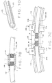
- a spacer 150 has a polygonal shaped outer contour; for example, it may have a hexagonal or octagonal outer contour. Such a construction results in at least one flat surface on the outer contour of the spacer.
- a spacer (turnbuckle) 160 has a threaded longitudinal bore 161 in which threaded ends of rings 102, 104 are received.
- the spacer has a uniform outer diameter throughout its length.
- each roller 112 moves freely within its respective pocket in bearing retainer 100 such that the load on any bridge element 206 is only a function of the mass of the roller 112 either ahead of or behind it, or a combination of the masses of both rollers, depending on the dynamic conditions.
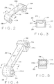
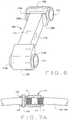
- bridge element 206 Different embodiments of bridge element 206 are shown in Figs. 2-6 . Regardless of the particular bridge element design, at each end of the bridge element an end block 208 is formed. The end blocks are axially spaced from each other and an eyelet 214 is formed in each end block. Each eyelet comprises a bore extending longitudinally through the end block, and the eyelets are sized to allow one of the rings 102, 104 to be inserted through a respective one of the end blocks as shown in Figs. 1 , 8 , and 9 .
- each bridge element 206 is separated by a retention web 216 which is attached to the inner surface of a bridge 215 that extends between the end blocks.
- Retention web 216 helps keep bridge element 206 in alignment with the external curvature of the rollers 112. This, in turn, helps restrict radial deflection of cage 100 during operation, as well as maintain adequate lubrication.
- a roller 112 travels through a load zone of the bearing, it moves through a pocket space S formed between adjacent bridge elements 206 until the roller contacts the bridge element rotationally ahead of it.
- retention web 216 of a bridge element 206 has straight and flat surfaces 217 (see Fig. 3 ) which distribute the contact load between a roller 112 and the bridge element.
- a contact region is disposed radially outward from the pitch diameter of the bearing in substantially the same location as the contact region provided by a conventional above centerline "L" type bearing cage. If retention web 216 does not extend radially inwardly past the bearing pitch diameter, additional space is provided between adjacent rollers 112 as to permit the storage and resupply of grease (or other lubricant) to the various contact regions located about the roller.
- bridge element 206 may be configured with a retention web 216 and bridge 215 in a position which is radially inward from the pitch circle or diameter of the bearing.
- the contact load between a roller 112 and a bridge element 206 is within a contact region which is correspondingly disposed radially inward from the pitch diameter of the bearing.
- the particular construction of a bridge 215 and retention web 216 depends upon the particular usage of the segmented bearing retainer 100.
- Construction of the bearing retainer or cage 100 is for use with a tapered bearing. Based on the size of an inner race 118 (see Figs. 1 and 8 ), the required diameters of rings 102, 104 are determined.
- each ring 102, 104 is initially open, thus allowing all of the bridge elements 206, spacers 110, and a turnbuckle 140 (see Fig. 1 ) if one is used, to be slipped onto and positioned around the respective rings.
- the number of spacers 110 is one less (N-1) than the number N of rollers 112 employed in the bearing.
- the number of bridge elements 206 equals the number N of rollers 112.
- a turnbuckle/spacer 141 has a radial bore 142 extending both through it and the ring 102, 104 whose ends are captured in the turnbuckle/spacer. An anti-rotation pin 143 is inserted through this bore.
- bore 142 extends only through one side of the turnbuckle/spacer and a set screw 144 is used to secure the turnbuckle/spacer to the ring.
- a weld W is formed at the inner end of a radial bore 162 in spacer 160 to attach the turnbuckle/spacer and the ring together.
- the ends of the spacer 141 can be crimped about the ends of the support ring inserted in the spacer. It will be appreciated that the ends of the ring can be secured to a turnbuckle/spacer using a combination of the above techniques. For example, one end of the ring may be threadably received in a turnbuckle with the other end of the ring crimped in place in the other end of it. Attachment of the ends of ring 102, 104 to the spacer can further be done using an adhesive material.
- the spacers 110 may float on the rings 102, 104 between the discrete bridge elements 206. Referring to Figs. 2 and 3 , the outer ends of the bores 214 formed in each end block 208 of a bridge element 206 are flush with the sides of the end block as described in the prior art document WO 2012092107 . Accordingly, spacers 110 installed between the adjacent bridge elements float between the bridge elements.
- each end block 208 includes a counter-bore 214cb formed at the outer end of each bore (eyelet) 214 that extends through the respective end block. As shown in Fig. 1 , the counter-bores are sized to receive the spacers 110.
- each end block 208 on a bridge segment 206 is formed to have a raised boss 214b surrounding the outer ends of each bore 214.
- the bosses 214b are sized to seat inside the inner end of an adjacent spacer 160 as shown in Fig. 7C .
- bearing retainer 100 is formed by supporting inner race 118 on a work table (or other surface) with its back face or large end facing downward.
- the assembled cage is then brought into position over and around the inner race.
- each roller 112 is inserted onto the assembly by moving the bridge elements 206 and spacers 110 circumferentially around the rings 102, 104 so to make space available for insertion of the next roller.
- the already assembled rollers 112, bridge segments 206, and spacers 110 are moved in opposite directions about the circumference of the rings thereby to create sufficient space into which to fit this roller. If required, after the last roller is inserted into place, a final bridge element 206 is installed to fill any remaining gap between the rollers 112.
- the ends of rings 102, 104 remain separated during the assembly process.
- the rings are brought into position over and around inner race 118 and are moved apart to create a circumferential gap of sufficient width to allow bridge elements 206 and spacers 110 to be slipped onto the rings.
- the bridge elements and spacers are spread equally around inner race 118 with rollers 112 positioned between them.
- the method used for joining the separated ends of rings 102, 104 must close the gap between the installed components so a correct amount of circumferential clearance exists in the "stack up" of spacers 110 and bridge elements 206. This is conveniently accomplished by modifying the width(s) of one or more spacers, if necessary.
- one or more spacers 110 are fixed to a ring 102, 104 by welding. This will limit the stack up of accumulated gap between each of the fixed spacers, including the turnbuckle spacer.
- the spacers 141, 150, and 160 have a radial bore 142, 162 respectively, in which a welding material is deposited.
- a spacer 170 is a split spacer having a longitudinal slot 171 extending the length of the spacer as shown in Fig. 10 . When spacer 170 is used, the welding material is deposited in slot 171 to attach the spacer to a ring 102, 104.
- bearing retainer 100 of the present disclosure is configured to provide an improved flow of lubricant to critical wear surfaces within the bearing assembly; for example, between bridge elements 206 and rollers 112.
- Use of circular cross-section rings 102, 104 and eyelet couplings 214 for the bridge elements provides openings for the axial movement of lubricant into the spaces between adjacent rollers.
- exposed surfaces of the bridge elements or segments may receive special finishes or textures to entrap and release lubricants in the contact regions between the bridge elements and rollers.
- the bridge segments are preferably made of a powdered metal, they may also be formed from a variety of materials including polymers and metals.
- suitable constructions include a compacted and sintered powered metal or steel construction which produces very strong bridge elements suitable for use with very large and heavy bearing designs, and which can optionally be impregnated (for example, by vacuum impregnation) with lubricating materials so to provide improved resistance to wear at critical surfaces within the bearing assembly.
- These type bridge elements may also have surface features or finishes which promote the trapping and releasing of lubricants.
Landscapes
- Engineering & Computer Science (AREA)
- General Engineering & Computer Science (AREA)
- Mechanical Engineering (AREA)
- Rolling Contact Bearings (AREA)
Applications Claiming Priority (2)
| Application Number | Priority Date | Filing Date | Title |
|---|---|---|---|
| US201261654159P | 2012-06-01 | 2012-06-01 | |
| PCT/US2013/029100 WO2013180774A1 (en) | 2012-06-01 | 2013-03-05 | Improved segmented bearing retainer |
Publications (2)
| Publication Number | Publication Date |
|---|---|
| EP2855954A1 EP2855954A1 (en) | 2015-04-08 |
| EP2855954B1 true EP2855954B1 (en) | 2017-05-10 |
Family
ID=48050239
Family Applications (1)
| Application Number | Title | Priority Date | Filing Date |
|---|---|---|---|
| EP13714732.8A Active EP2855954B1 (en) | 2012-06-01 | 2013-03-05 | Improved segmented bearing retainer |
Country Status (5)
| Country | Link |
|---|---|
| US (1) | US9039289B2 (da) |
| EP (1) | EP2855954B1 (da) |
| CN (1) | CN104334899B (da) |
| DK (1) | DK2855954T3 (da) |
| WO (1) | WO2013180774A1 (da) |
Families Citing this family (12)
| Publication number | Priority date | Publication date | Assignee | Title |
|---|---|---|---|---|
| DE102012101651A1 (de) * | 2012-02-29 | 2013-08-29 | Thyssenkrupp Rothe Erde Gmbh | Verfahren zur Herstellung eines Wälzlagerkäfigs für ein Axial-Radial-Wälzlager sowie Axial-Radial-Wälzlager |
| DE102013224541A1 (de) * | 2013-11-29 | 2015-06-03 | Aktiebolaget Skf | Wälzlager |
| DE102014205817A1 (de) * | 2014-03-28 | 2015-10-01 | Aktiebolaget Skf | Wälzlagerkäfig und Verfahren zur Montage eines Wälzlagerkäfigs |
| DE102014207836B4 (de) * | 2014-04-25 | 2016-02-18 | Aktiebolaget Skf | Wälzlager |
| DE102015225259B4 (de) * | 2015-12-15 | 2018-10-11 | Schaeffler Technologies AG & Co. KG | Segmentwälzlager und Scheibenbremsenvorrichtung |
| GB2550420A (en) | 2016-05-20 | 2017-11-22 | Bowman Int Ltd | Rolling element bearing cage |
| CN108361281B (zh) * | 2017-01-26 | 2021-01-01 | 斯凯孚公司 | 保持架分段、分段式保持架和轴承 |
| WO2018174979A1 (en) | 2017-03-24 | 2018-09-27 | The Timken Company | Seal carrier arrangement for large diameter bearing |
| DE102017217810A1 (de) * | 2017-10-06 | 2019-04-11 | Aktiebolaget Skf | Anordnung für ein Wälzlager |
| DE102017222783A1 (de) * | 2017-12-14 | 2019-06-19 | Aktiebolaget Skf | Käfigsegment für einen Wälzlagerkäfig |
| CN114483776B (zh) * | 2022-01-28 | 2023-10-24 | 中国铁建重工集团股份有限公司 | 一种掘进机主轴承及其装配方法 |
| US11892036B1 (en) * | 2022-07-22 | 2024-02-06 | Schaeffler Technologies AG & Co. KG | Bearing track cage for mitigating rolling element excursion |
Family Cites Families (46)
| Publication number | Priority date | Publication date | Assignee | Title |
|---|---|---|---|---|
| FR362512A (fr) | 1906-01-18 | 1906-06-27 | Maurice Fouquet | Roulement à billes |
| US930599A (en) | 1906-02-21 | 1909-08-10 | Henry Hess | Ball-bearing. |
| US847261A (en) | 1906-10-04 | 1907-03-12 | Gustaf Rennerfelt | Roller-bearing. |
| US1996841A (en) | 1931-05-06 | 1935-04-09 | Gen Motors Corp | Separator |
| US3284146A (en) | 1965-01-08 | 1966-11-08 | John B Ripple | Roller-bearing cages |
| US3582164A (en) | 1969-06-09 | 1971-06-01 | Rollway Bearing Co Inc | Powdered metal bearing cage |
| IT8553062U1 (it) | 1985-03-01 | 1986-09-01 | Riv Skf Officine Di Villar Perosa S P A | Gabbia distanziatrice per le sfere di un cuscinetto a sfere |
| DE8621532U1 (de) | 1986-08-11 | 1987-12-23 | Gugel, Georg, Dipl.-Ing., 8552 Höchstadt | Käfigelement für Kreuzrollenlager |
| DE4027109A1 (de) | 1990-08-28 | 1992-03-05 | Hoesch Ag | Kaefig fuer ein waelzlager |
| GB2280937B (en) | 1993-08-12 | 1997-01-15 | Torrington Co | Improvements in bearing split cages |
| US5404642A (en) | 1994-01-31 | 1995-04-11 | The Torrington Company | Method of assembling a bearing |
| US6068408A (en) | 1995-10-19 | 2000-05-30 | Nsk Ltd. | Cage for a rolling bearing |
| JPH09242759A (ja) | 1996-03-11 | 1997-09-16 | Nippon Seiko Kk | コロ軸受 |
| US5660485A (en) | 1996-06-20 | 1997-08-26 | The Torrington Company | Modular retainer assembly |
| DE19646310A1 (de) | 1996-11-09 | 1998-05-14 | Skf Gmbh | Radial-Wälzlager |
| JP3550689B2 (ja) | 1998-05-20 | 2004-08-04 | 日本精工株式会社 | 固体潤滑転がり軸受 |
| JP4147500B2 (ja) | 1998-08-04 | 2008-09-10 | ミネベア株式会社 | 転がり軸受用保持器 |
| DE19959498A1 (de) | 1999-12-10 | 2001-06-13 | Schaeffler Waelzlager Ohg | Käfig für ein Wälzlager |
| JP4515589B2 (ja) | 2000-03-21 | 2010-08-04 | Thk株式会社 | ローラ用リテーナ及びこれを用いた直動案内装置並びにローラねじ |
| DE10335415B4 (de) | 2003-08-02 | 2006-08-03 | Ab Skf | Wälzlager |
| EP1614914B1 (en) | 2004-07-05 | 2014-01-15 | NTN Corporation | Tapered roller bearing |
| US7507028B2 (en) | 2005-06-27 | 2009-03-24 | Spx Corporation | Bearing retainer assembly and method |
| EP1741941B1 (en) | 2005-07-04 | 2010-08-18 | NTN Corporation | Needle roller bearing with a retainer and manufacturing method of the retainer |
| EP1961983B1 (en) | 2005-12-16 | 2012-03-07 | NTN Corporation | Roller bearing, main shaft support structure for wind-driven generator, intermediate element, and retainer segment |
| CN105003540B (zh) | 2006-03-10 | 2018-07-27 | Ntn株式会社 | 衬垫 |
| DK2511544T4 (da) | 2006-09-08 | 2021-11-15 | Ntn Toyo Bearing Co Ltd | Holdedel til et rulleleje, som kan bære en hovedaksel i et vindkraftværk |
| DE102006045436A1 (de) | 2006-09-26 | 2008-03-27 | Schaeffler Kg | Wälzlagerkäfig und Verfahren zur Herstellung desselben |
| DE102006047544A1 (de) | 2006-10-07 | 2008-04-10 | Schaeffler Kg | Metallkäfig für Rollenlager |
| JP4848964B2 (ja) | 2007-01-19 | 2011-12-28 | 株式会社ジェイテクト | 転がり軸受用保持器 |
| GB2448687B (en) | 2007-04-23 | 2011-07-06 | Cooper Roller Bearings Company | A Cage for a roller bearing and a roller bearing |
| DE102007020113A1 (de) | 2007-04-28 | 2008-10-30 | Aktiebolaget Skf | Wälzlagerkäfig |
| DE102007031792A1 (de) | 2007-07-07 | 2009-01-08 | Schaeffler Kg | Wälzlager, insbesondere Rollenlager |
| DE102007052507B4 (de) | 2007-11-02 | 2016-06-02 | Ab Skf | Wälzlagerkäfig |
| DE202008014280U1 (de) | 2008-10-27 | 2010-04-08 | Ab Skf | Wälzlagerkäfig |
| DE102008053313B4 (de) | 2008-10-27 | 2016-10-20 | Ab Skf | Rollenlagerkäfig |
| DE102009006858A1 (de) | 2009-01-30 | 2010-08-05 | Ab Skf | Wälzlagerkäfig |
| US8167501B2 (en) | 2009-02-02 | 2012-05-01 | Hamilton Sundstrand Corporation | Separator for bearing assemblies with cyclic loads |
| DE102009040008A1 (de) | 2009-09-03 | 2011-03-10 | Schaeffler Technologies Gmbh & Co. Kg | Käfig für ein Wälzlager und Wälzlager |
| WO2011031931A1 (en) * | 2009-09-11 | 2011-03-17 | The Timken Company | Snap-on cage bridge for rolling element bearings |
| JP5334789B2 (ja) | 2009-10-16 | 2013-11-06 | Ntn株式会社 | 転がり軸受 |
| JP5757703B2 (ja) | 2009-12-25 | 2015-07-29 | Ntn株式会社 | 円すいころ軸受 |
| JP5702534B2 (ja) * | 2009-12-29 | 2015-04-15 | Ntn株式会社 | 円すいころ軸受の分割型保持器 |
| JP5599196B2 (ja) | 2010-02-10 | 2014-10-01 | 株式会社ハーモニック・ドライブ・システムズ | クロスローラーベアリング |
| DE102010062712A1 (de) | 2010-12-09 | 2012-06-14 | Aktiebolaget Skf | Wälzlager mit neuem Käfigkonzept und Montageverfahren für ein Lager |
| DK2659153T3 (da) | 2010-12-27 | 2017-11-06 | Timken Co | Lejehus til rulleleje samlet af to trådringe og et antal stiver eller tapper |
| DE102011003442A1 (de) | 2011-02-01 | 2012-08-02 | Schaeffler Technologies Gmbh & Co. Kg | Wälzlagerkäfig und Wälzlager |
-
2013
- 2013-03-05 DK DK13714732.8T patent/DK2855954T3/da active
- 2013-03-05 EP EP13714732.8A patent/EP2855954B1/en active Active
- 2013-03-05 WO PCT/US2013/029100 patent/WO2013180774A1/en not_active Ceased
- 2013-03-05 US US14/384,707 patent/US9039289B2/en active Active
- 2013-03-05 CN CN201380023691.0A patent/CN104334899B/zh active Active
Also Published As
| Publication number | Publication date |
|---|---|
| EP2855954A1 (en) | 2015-04-08 |
| CN104334899A (zh) | 2015-02-04 |
| US20150063738A1 (en) | 2015-03-05 |
| US9039289B2 (en) | 2015-05-26 |
| CN104334899B (zh) | 2016-09-28 |
| WO2013180774A1 (en) | 2013-12-05 |
| DK2855954T3 (da) | 2017-08-28 |
Similar Documents
| Publication | Publication Date | Title |
|---|---|---|
| EP2855954B1 (en) | Improved segmented bearing retainer | |
| US8926190B2 (en) | Segmented bearing retainer | |
| US7845857B2 (en) | Thrust bearing assembly | |
| US20130188900A1 (en) | Bearing cage segment, bearing cage and method for manufacturing the same | |
| EP3376077B1 (en) | V-springs, seals with v-springs, and related methods | |
| DE102011004374A1 (de) | Lagerkäfigsegment, Lagerkäfig und Verfahren zur Herstellung desselben | |
| US20160107480A1 (en) | Wheel bearing retainer and methods thereof | |
| US20100166355A1 (en) | Metal cage for roller bearing | |
| WO2013092217A1 (de) | Lagerkäfig, lagerkäfigsegment und verfahren zum zusammenbau des lagerkäfigs | |
| EP3002472B1 (en) | A segmented outer ring for a bearing for mitigating torque degradation | |
| WO2017020905A1 (de) | Schrägrollenlager sowie verfahren und vorrichtung zu dessen montage | |
| US20150071579A1 (en) | Rolling bearing having rings with stepped surfaces opposite to the raceways | |
| US9103377B2 (en) | Self lubricating robust centralizer bearing design and method of use | |
| DE102019107754A1 (de) | Käfig- und walzenbaugruppe | |
| US2251714A (en) | Roller bearing, particularly for aircraft shock absorbers | |
| DE102014224130A1 (de) | Lageranordnung | |
| DE19839486A1 (de) | Radialwälzlager | |
| EP3129667A1 (de) | Lageranordnung mit einem käfig | |
| US10422386B2 (en) | Bearing lock, bearing assembly and associated method | |
| KR102920455B1 (ko) | 테이퍼 롤러 베어링 | |
| JP5790032B2 (ja) | 円すいころ軸受 | |
| US20010045015A1 (en) | Assembly technique for double row ball or roller bearings | |
| JP5790033B2 (ja) | 円すいころ軸受 | |
| JP2005114029A (ja) | 分割型転がり軸受 | |
| DE1840715U (de) | Lageranordnung. |
Legal Events
| Date | Code | Title | Description |
|---|---|---|---|
| PUAI | Public reference made under article 153(3) epc to a published international application that has entered the european phase |
Free format text: ORIGINAL CODE: 0009012 |
|
| 17P | Request for examination filed |
Effective date: 20141203 |
|
| AK | Designated contracting states |
Kind code of ref document: A1 Designated state(s): AL AT BE BG CH CY CZ DE DK EE ES FI FR GB GR HR HU IE IS IT LI LT LU LV MC MK MT NL NO PL PT RO RS SE SI SK SM TR |
|
| AX | Request for extension of the european patent |
Extension state: BA ME |
|
| DAX | Request for extension of the european patent (deleted) | ||
| 17Q | First examination report despatched |
Effective date: 20150901 |
|
| RIN1 | Information on inventor provided before grant (corrected) |
Inventor name: MARKS, CHRISTOPHER, S. Inventor name: CALVIN, JEFFREY SCOTT L. Inventor name: SIMMONS, MICHAEL D. Inventor name: RYBKOSKI, THOMAS, J. Inventor name: FOX, GERALD, P. Inventor name: LANDIN, HANS Inventor name: WERNER, BRIAN |
|
| GRAP | Despatch of communication of intention to grant a patent |
Free format text: ORIGINAL CODE: EPIDOSNIGR1 |
|
| INTG | Intention to grant announced |
Effective date: 20170127 |
|
| GRAS | Grant fee paid |
Free format text: ORIGINAL CODE: EPIDOSNIGR3 |
|
| GRAA | (expected) grant |
Free format text: ORIGINAL CODE: 0009210 |
|
| AK | Designated contracting states |
Kind code of ref document: B1 Designated state(s): AL AT BE BG CH CY CZ DE DK EE ES FI FR GB GR HR HU IE IS IT LI LT LU LV MC MK MT NL NO PL PT RO RS SE SI SK SM TR |
|
| REG | Reference to a national code |
Ref country code: GB Ref legal event code: FG4D |
|
| REG | Reference to a national code |
Ref country code: AT Ref legal event code: REF Ref document number: 892671 Country of ref document: AT Kind code of ref document: T Effective date: 20170515 Ref country code: CH Ref legal event code: EP |
|
| REG | Reference to a national code |
Ref country code: IE Ref legal event code: FG4D |
|
| REG | Reference to a national code |
Ref country code: DE Ref legal event code: R096 Ref document number: 602013020931 Country of ref document: DE |
|
| RAP2 | Party data changed (patent owner data changed or rights of a patent transferred) |
Owner name: THE TIMKEN COMPANY |
|
| REG | Reference to a national code |
Ref country code: RO Ref legal event code: EPE |
|
| REG | Reference to a national code |
Ref country code: DK Ref legal event code: T3 Effective date: 20170825 |
|
| REG | Reference to a national code |
Ref country code: NL Ref legal event code: MP Effective date: 20170510 |
|
| REG | Reference to a national code |
Ref country code: LT Ref legal event code: MG4D |
|
| REG | Reference to a national code |
Ref country code: AT Ref legal event code: MK05 Ref document number: 892671 Country of ref document: AT Kind code of ref document: T Effective date: 20170510 |
|
| PG25 | Lapsed in a contracting state [announced via postgrant information from national office to epo] |
Ref country code: GR Free format text: LAPSE BECAUSE OF FAILURE TO SUBMIT A TRANSLATION OF THE DESCRIPTION OR TO PAY THE FEE WITHIN THE PRESCRIBED TIME-LIMIT Effective date: 20170811 Ref country code: HR Free format text: LAPSE BECAUSE OF FAILURE TO SUBMIT A TRANSLATION OF THE DESCRIPTION OR TO PAY THE FEE WITHIN THE PRESCRIBED TIME-LIMIT Effective date: 20170510 Ref country code: FI Free format text: LAPSE BECAUSE OF FAILURE TO SUBMIT A TRANSLATION OF THE DESCRIPTION OR TO PAY THE FEE WITHIN THE PRESCRIBED TIME-LIMIT Effective date: 20170510 Ref country code: ES Free format text: LAPSE BECAUSE OF FAILURE TO SUBMIT A TRANSLATION OF THE DESCRIPTION OR TO PAY THE FEE WITHIN THE PRESCRIBED TIME-LIMIT Effective date: 20170510 Ref country code: LT Free format text: LAPSE BECAUSE OF FAILURE TO SUBMIT A TRANSLATION OF THE DESCRIPTION OR TO PAY THE FEE WITHIN THE PRESCRIBED TIME-LIMIT Effective date: 20170510 Ref country code: AT Free format text: LAPSE BECAUSE OF FAILURE TO SUBMIT A TRANSLATION OF THE DESCRIPTION OR TO PAY THE FEE WITHIN THE PRESCRIBED TIME-LIMIT Effective date: 20170510 Ref country code: NO Free format text: LAPSE BECAUSE OF FAILURE TO SUBMIT A TRANSLATION OF THE DESCRIPTION OR TO PAY THE FEE WITHIN THE PRESCRIBED TIME-LIMIT Effective date: 20170810 |
|
| PG25 | Lapsed in a contracting state [announced via postgrant information from national office to epo] |
Ref country code: NL Free format text: LAPSE BECAUSE OF FAILURE TO SUBMIT A TRANSLATION OF THE DESCRIPTION OR TO PAY THE FEE WITHIN THE PRESCRIBED TIME-LIMIT Effective date: 20170510 Ref country code: IS Free format text: LAPSE BECAUSE OF FAILURE TO SUBMIT A TRANSLATION OF THE DESCRIPTION OR TO PAY THE FEE WITHIN THE PRESCRIBED TIME-LIMIT Effective date: 20170910 Ref country code: LV Free format text: LAPSE BECAUSE OF FAILURE TO SUBMIT A TRANSLATION OF THE DESCRIPTION OR TO PAY THE FEE WITHIN THE PRESCRIBED TIME-LIMIT Effective date: 20170510 Ref country code: BG Free format text: LAPSE BECAUSE OF FAILURE TO SUBMIT A TRANSLATION OF THE DESCRIPTION OR TO PAY THE FEE WITHIN THE PRESCRIBED TIME-LIMIT Effective date: 20170810 Ref country code: PL Free format text: LAPSE BECAUSE OF FAILURE TO SUBMIT A TRANSLATION OF THE DESCRIPTION OR TO PAY THE FEE WITHIN THE PRESCRIBED TIME-LIMIT Effective date: 20170510 Ref country code: RS Free format text: LAPSE BECAUSE OF FAILURE TO SUBMIT A TRANSLATION OF THE DESCRIPTION OR TO PAY THE FEE WITHIN THE PRESCRIBED TIME-LIMIT Effective date: 20170510 Ref country code: SE Free format text: LAPSE BECAUSE OF FAILURE TO SUBMIT A TRANSLATION OF THE DESCRIPTION OR TO PAY THE FEE WITHIN THE PRESCRIBED TIME-LIMIT Effective date: 20170510 |
|
| PG25 | Lapsed in a contracting state [announced via postgrant information from national office to epo] |
Ref country code: CZ Free format text: LAPSE BECAUSE OF FAILURE TO SUBMIT A TRANSLATION OF THE DESCRIPTION OR TO PAY THE FEE WITHIN THE PRESCRIBED TIME-LIMIT Effective date: 20170510 Ref country code: SK Free format text: LAPSE BECAUSE OF FAILURE TO SUBMIT A TRANSLATION OF THE DESCRIPTION OR TO PAY THE FEE WITHIN THE PRESCRIBED TIME-LIMIT Effective date: 20170510 Ref country code: EE Free format text: LAPSE BECAUSE OF FAILURE TO SUBMIT A TRANSLATION OF THE DESCRIPTION OR TO PAY THE FEE WITHIN THE PRESCRIBED TIME-LIMIT Effective date: 20170510 |
|
| REG | Reference to a national code |
Ref country code: DE Ref legal event code: R097 Ref document number: 602013020931 Country of ref document: DE |
|
| PG25 | Lapsed in a contracting state [announced via postgrant information from national office to epo] |
Ref country code: SM Free format text: LAPSE BECAUSE OF FAILURE TO SUBMIT A TRANSLATION OF THE DESCRIPTION OR TO PAY THE FEE WITHIN THE PRESCRIBED TIME-LIMIT Effective date: 20170510 |
|
| PLBE | No opposition filed within time limit |
Free format text: ORIGINAL CODE: 0009261 |
|
| STAA | Information on the status of an ep patent application or granted ep patent |
Free format text: STATUS: NO OPPOSITION FILED WITHIN TIME LIMIT |
|
| REG | Reference to a national code |
Ref country code: FR Ref legal event code: PLFP Year of fee payment: 6 |
|
| 26N | No opposition filed |
Effective date: 20180213 |
|
| PG25 | Lapsed in a contracting state [announced via postgrant information from national office to epo] |
Ref country code: SI Free format text: LAPSE BECAUSE OF FAILURE TO SUBMIT A TRANSLATION OF THE DESCRIPTION OR TO PAY THE FEE WITHIN THE PRESCRIBED TIME-LIMIT Effective date: 20170510 |
|
| REG | Reference to a national code |
Ref country code: CH Ref legal event code: PL |
|
| PG25 | Lapsed in a contracting state [announced via postgrant information from national office to epo] |
Ref country code: MC Free format text: LAPSE BECAUSE OF FAILURE TO SUBMIT A TRANSLATION OF THE DESCRIPTION OR TO PAY THE FEE WITHIN THE PRESCRIBED TIME-LIMIT Effective date: 20170510 |
|
| REG | Reference to a national code |
Ref country code: BE Ref legal event code: MM Effective date: 20180331 |
|
| REG | Reference to a national code |
Ref country code: IE Ref legal event code: MM4A |
|
| PG25 | Lapsed in a contracting state [announced via postgrant information from national office to epo] |
Ref country code: LU Free format text: LAPSE BECAUSE OF NON-PAYMENT OF DUE FEES Effective date: 20180305 |
|
| PG25 | Lapsed in a contracting state [announced via postgrant information from national office to epo] |
Ref country code: IE Free format text: LAPSE BECAUSE OF NON-PAYMENT OF DUE FEES Effective date: 20180305 |
|
| PG25 | Lapsed in a contracting state [announced via postgrant information from national office to epo] |
Ref country code: LI Free format text: LAPSE BECAUSE OF NON-PAYMENT OF DUE FEES Effective date: 20180331 Ref country code: BE Free format text: LAPSE BECAUSE OF NON-PAYMENT OF DUE FEES Effective date: 20180331 Ref country code: CH Free format text: LAPSE BECAUSE OF NON-PAYMENT OF DUE FEES Effective date: 20180331 |
|
| PG25 | Lapsed in a contracting state [announced via postgrant information from national office to epo] |
Ref country code: MT Free format text: LAPSE BECAUSE OF NON-PAYMENT OF DUE FEES Effective date: 20180305 |
|
| PG25 | Lapsed in a contracting state [announced via postgrant information from national office to epo] |
Ref country code: TR Free format text: LAPSE BECAUSE OF FAILURE TO SUBMIT A TRANSLATION OF THE DESCRIPTION OR TO PAY THE FEE WITHIN THE PRESCRIBED TIME-LIMIT Effective date: 20170510 |
|
| PG25 | Lapsed in a contracting state [announced via postgrant information from national office to epo] |
Ref country code: PT Free format text: LAPSE BECAUSE OF FAILURE TO SUBMIT A TRANSLATION OF THE DESCRIPTION OR TO PAY THE FEE WITHIN THE PRESCRIBED TIME-LIMIT Effective date: 20170510 |
|
| PG25 | Lapsed in a contracting state [announced via postgrant information from national office to epo] |
Ref country code: MK Free format text: LAPSE BECAUSE OF NON-PAYMENT OF DUE FEES Effective date: 20170510 Ref country code: CY Free format text: LAPSE BECAUSE OF FAILURE TO SUBMIT A TRANSLATION OF THE DESCRIPTION OR TO PAY THE FEE WITHIN THE PRESCRIBED TIME-LIMIT Effective date: 20170510 Ref country code: HU Free format text: LAPSE BECAUSE OF FAILURE TO SUBMIT A TRANSLATION OF THE DESCRIPTION OR TO PAY THE FEE WITHIN THE PRESCRIBED TIME-LIMIT; INVALID AB INITIO Effective date: 20130305 |
|
| PG25 | Lapsed in a contracting state [announced via postgrant information from national office to epo] |
Ref country code: AL Free format text: LAPSE BECAUSE OF FAILURE TO SUBMIT A TRANSLATION OF THE DESCRIPTION OR TO PAY THE FEE WITHIN THE PRESCRIBED TIME-LIMIT Effective date: 20170510 |
|
| P01 | Opt-out of the competence of the unified patent court (upc) registered |
Effective date: 20230613 |
|
| REG | Reference to a national code |
Ref country code: DE Ref legal event code: R082 Ref document number: 602013020931 Country of ref document: DE Representative=s name: KRAUS & LEDERER PARTGMBB, DE |
|
| PGFP | Annual fee paid to national office [announced via postgrant information from national office to epo] |
Ref country code: DE Payment date: 20250319 Year of fee payment: 13 |
|
| PGFP | Annual fee paid to national office [announced via postgrant information from national office to epo] |
Ref country code: DK Payment date: 20250326 Year of fee payment: 13 Ref country code: RO Payment date: 20250224 Year of fee payment: 13 |
|
| PGFP | Annual fee paid to national office [announced via postgrant information from national office to epo] |
Ref country code: FR Payment date: 20250325 Year of fee payment: 13 |
|
| PGFP | Annual fee paid to national office [announced via postgrant information from national office to epo] |
Ref country code: IT Payment date: 20250325 Year of fee payment: 13 Ref country code: GB Payment date: 20250321 Year of fee payment: 13 |