EP2855972B1 - Geflochtenes endstück für eine fasernabelschnur unter wasser - Google Patents
Geflochtenes endstück für eine fasernabelschnur unter wasser Download PDFInfo
- Publication number
- EP2855972B1 EP2855972B1 EP13793115.0A EP13793115A EP2855972B1 EP 2855972 B1 EP2855972 B1 EP 2855972B1 EP 13793115 A EP13793115 A EP 13793115A EP 2855972 B1 EP2855972 B1 EP 2855972B1
- Authority
- EP
- European Patent Office
- Prior art keywords
- umbilical
- lifting
- fiber
- load
- subsea equipment
- Prior art date
- Legal status (The legal status is an assumption and is not a legal conclusion. Google has not performed a legal analysis and makes no representation as to the accuracy of the status listed.)
- Active
Links
Images

Classifications
-
- F—MECHANICAL ENGINEERING; LIGHTING; HEATING; WEAPONS; BLASTING
- F16—ENGINEERING ELEMENTS AND UNITS; GENERAL MEASURES FOR PRODUCING AND MAINTAINING EFFECTIVE FUNCTIONING OF MACHINES OR INSTALLATIONS; THERMAL INSULATION IN GENERAL
- F16G—BELTS, CABLES, OR ROPES, PREDOMINANTLY USED FOR DRIVING PURPOSES; CHAINS; FITTINGS PREDOMINANTLY USED THEREFOR
- F16G11/00—Means for fastening cables or ropes to one another or to other objects; Caps or sleeves for fixing on cables or ropes
-
- B—PERFORMING OPERATIONS; TRANSPORTING
- B65—CONVEYING; PACKING; STORING; HANDLING THIN OR FILAMENTARY MATERIAL
- B65H—HANDLING THIN OR FILAMENTARY MATERIAL, e.g. SHEETS, WEBS, CABLES
- B65H69/00—Methods of, or devices for, interconnecting successive lengths of material; Knot-tying devices ;Control of the correct working of the interconnecting device
- B65H69/06—Methods of, or devices for, interconnecting successive lengths of material; Knot-tying devices ;Control of the correct working of the interconnecting device by splicing
-
- D—TEXTILES; PAPER
- D07—ROPES; CABLES OTHER THAN ELECTRIC
- D07B—ROPES OR CABLES IN GENERAL
- D07B7/00—Details of, or auxiliary devices incorporated in, rope- or cable-making machines; Auxiliary apparatus associated with such machines
- D07B7/16—Auxiliary apparatus
- D07B7/169—Auxiliary apparatus for interconnecting two cable or rope ends, e.g. by splicing or sewing
-
- E—FIXED CONSTRUCTIONS
- E02—HYDRAULIC ENGINEERING; FOUNDATIONS; SOIL SHIFTING
- E02D—FOUNDATIONS; EXCAVATIONS; EMBANKMENTS; UNDERGROUND OR UNDERWATER STRUCTURES
- E02D15/00—Handling building or like materials for hydraulic engineering or foundations
- E02D15/08—Sinking workpieces into water or soil inasmuch as not provided for elsewhere
-
- E—FIXED CONSTRUCTIONS
- E21—EARTH OR ROCK DRILLING; MINING
- E21B—EARTH OR ROCK DRILLING; OBTAINING OIL, GAS, WATER, SOLUBLE OR MELTABLE MATERIALS OR A SLURRY OF MINERALS FROM WELLS
- E21B41/00—Equipment or details not covered by groups E21B15/00 - E21B40/00
- E21B41/0007—Equipment or details not covered by groups E21B15/00 - E21B40/00 for underwater installations
Definitions
- This disclosure relates to means to terminate a synthetic fiber strength member in a subsea umbilical line to provide a high strength lifting connection between the umbilical line and remotely operated seabed equipment.
- Umbilical lines known in the art for subsea equipment including remotely operated vehicles (ROVs), seabed drill rigs, and trenching systems include steel-jacketed umbilical cable, wherein outer windings of steel wire are disposed on the exterior of electrical and/or optical conductors.
- the steel wires form a strength member for lifting loads through the water column using the umbilical cable.
- Such cables may be terminated in a "bullet” using a curable potting material that becomes solid and thereby locks the steel wires into the bullet.
- Bullets using curable potting material are also commonly to terminate umbilical cables that use synthetic fiber for the strength member, but due to the different physical properties of certain types of fiber when compared to steel, such terminations usually fail at less than 60% of the actual breaking strength of the fiber strength member. It is possible to use more fiber in the strength member to increase the breaking strength of terminations known in the art, however, more fiber increases the weight of the umbilical cable, thus limiting the depth to which the umbilical cable may be deployed.
- GB2332946 describes a method for coupling a fiber strength member umbilical cable to a subsea equipment load transfer device using a kelum grip. US4225172 describes kelum grips. What is needed is a stronger termination for fiber strength member umbilical cables that does not require increasing the breaking strength of the strength member itself by adding material thereto.
- a braiding process is used to weave a high-strength synthetic fiber harness into a terminating end of an umbilical cable, resulting in a termination which may exceeds 90% of the umbilical cable breaking strength.
- An umbilical cable 1 which may include fiber (e.g., synthetic fiber) disposed about insulated electrical and/or optical conductors extends into water from a vessel 1A born crane 1B or launch and recovery system (LARS) of any type known in the art.
- the umbilical cable 1 may have an inner core 3 (e.g., electrical and/or optical conductors) and an outer, or strength core (not shown separately) made of fiber such as those sold, as nonlimiting examples, under the trademarks KEVLAR (which is a registered trademark of E. I.
- the inner core 3 of the umbilical 1 may include, as explained above, insulated electrical conductor wires and/or fiber optic cables for power and control of the subsea equipment 6.
- a harness 4A made of high strength synthetic fibers 4 may be connected to the umbilical 1 by a braiding process.
- the braided harness 4A may be attached to the subsea equipment 6 using a lifting connector 5, examples of which will be further explained below.
- the subsea equipment 6 may be connected to the inner core 3 of the umbilical 1 for power and control, and the equipment 6 may be raised and lowered to the water bottom or seabed 7 with the weight carried by the harness 4A as it is coupled to the lifting connector 5 on the subsea equipment 6.
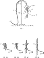
- the umbilical shown at 8 in FIG. 2
- the umbilical may be cut at a selected location after being disposed on a suitable fixture 13 on a stand 12, and the outer jacket is stripped off to reveal the strength fibers 9, which may be separated into bundles for braiding.
- the umbilical fiber bundles and harness bundles, also shown at 9, may be aligned in preparation for braiding.
- the inner core 10 of the umbilical 8 is brought through the center of the braiding area.
- the braiding harness has at least one lifting loop 11 which, when attached to the subsea equipment (e.g., connector 5 in FIG. 1 ) will transfer the load from the equipment (6 in FIG. 1 ) to the umbilical 8.
- the lifting loop 11 may be pre-formed prior to attachment to the umbilical 8 by looping a length of fiber, which may be similar in configuration to the fibers that form the jacket of the umbilical 8, and braiding the ends thereof to form a closed loop as shown with a selected length extension 11A.
- the extension 11A may have its fibers exposed, as shown at 11B, for braiding to the exposed fibers 9 at the end of the umbilical cable 8.
- the subsea equipment e.g., connector 5 in FIG. 1
- the lifting loop 11 may be pre-formed prior to attachment to the umbilical 8 by looping a length of fiber, which may be similar in configuration to the fibers that form the jacket of the umbilical 8, and braiding the ends thereof to form a closed loop as shown with a selected length
- the lifting loop 11 may be formed first and then engaged with a suitable component of the subsea equipment (6 in FIG. 1 ), or may be looped around a suitable termination component of the subsea equipment prior to braiding the lifting loop 11 to form a closed loop.
- Pre-forming as shown in FIG. 2 may be used advantageously in some examples to have a ready termination for coupling to the subsea equipment (6 in FIG. 1 ).
- FIG. 3A the fiber bundles 14, made of the umbilical strength fibers (2 in FIG. 1 ; 9 in FIG. 2 ) and harness fibers (4 in FIG. 1 ; 11B in FIG. 2 ) are brought together and interlaced.
- the fiber bundles of the umbilical and harness are woven into each other above and below an initial attachment point 15 as shown in FIG. 3B .
- Braiding proceeds to a pre-determined length (axial distance 16 from the initial attachment point 15) in order to obtain a selected breaking strength as shown in FIG. 3C .
- Excess fiber 17 may be trimmed and tucked into the braided length (16 in FIG. 3C ) as shown in FIG. 3D , completing the connection of the harness (11 in FIG. 2 ) to the umbilical (8 in FIG. 2 ).
- the core of the umbilical is shown at 10 in each of FIGS. 3A through 3D .
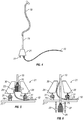
- the umbilical shown at 18 and prepared as described with reference to FIGS. 2 and 3A-D , may be removed from the braiding frame (13 in FIG. 2 ) and may then be extended to a subsea equipment lifting point 21, which may include lifting tabs 22.
- the braided section 19 of the umbilical 18 may be fed into a lifting "bullet" system 21 which, depending upon the selected configuration, may either act as the termination point for the umbilical ( FIG. 5 ) or may be non-load bearing ( FIG. 6 ).
- the inner core 10 of the umbilical 18 may be led from the attachment point and may be connected to the subsea equipment (6 in FIG. 1 ) to provide power and control as explained above.
- the lifting bullet (21 in FIG. 4 ) may be connected to the subsea equipment, explained below.
- Lifting tabs 22 may secure the lifting bullet 21 to the equipment (6 in FIG. 1 ).
- a load transfer device may include a pin 23 secured to a load transfer element, e.g. a lifting sheave 25 into the interior of a lifting bullet 30.
- the lifting sheave 25 may have multiple grooves 24 to support multiple loops of the lifting harness.
- the strength fibers of the lifting harness may be divided into multiple loops to distribute the lifting load across the lifting sheave 25.
- the inner core 10 of the umbilical (18 in FIG. 4 ) is led from the attachment point and connected, e.g., through a suitable pressure proof connector, to the subsea equipment (6 in FIG. 1 ) to provide power and control.
- a load-bearing frame 27 of the subsea equipment (6 in FIG. 1 ) may serve as the attachment point for the bullet 30.
- Tabs 28 on the bottom of the bullet 30 may attach with a pin 31 to corresponding tabs 29 on the subsea equipment load bearing frame 27.
- the lifting bullet 30 takes the load transferred by the umbilical termination and transmits it to the subsea equipment frame 27 via the attachment tabs 28.
- the braided section 19 of the subsea umbilical termination transmits the lifting force from the umbilical termination to the umbilical (18 in FIG. 4 ).
- a pin 23 secures the lifting sheave 25 to termination support brackets 32.
- the lifting sheave 25 as in the previous example, may have multiple grooves 24 to support multiple loops of the lifting harness (18 in FIG. 4 ). Also as in the previous example, the lifting harness may be divided into multiple loops to distribute the lifting load across the lifting sheave. 25
- the inner core 10 of the umbilical may be led from the attachment point and connected to the subsea equipment to provide power and control.
- the load-bearing frame 27 of the subsea equipment (6 in FIG. 1 ) serves as the attachment point for the bullet 30.
- Tabs 28 on the bottom of the bullet 30 attach with a pin 31 to corresponding tabs 29 on the subsea equipment load-bearing frame 27.
- the lifting bullet 30 takes the subsea equipment load, when the bullet is locked into a launch and recovery system, and transmits it to the subsea equipment frame via the attachment tabs 28, 29.
- the braided section 19 of the subsea umbilical transmits the lifting force from the umbilical termination to the umbilical (18 in FIG. 4 ).
- the termination support brackets 32 transfer the load to the subsea equipment load-bearing frame 27.
Landscapes
- Engineering & Computer Science (AREA)
- General Engineering & Computer Science (AREA)
- Life Sciences & Earth Sciences (AREA)
- Mining & Mineral Resources (AREA)
- Geology (AREA)
- General Life Sciences & Earth Sciences (AREA)
- Structural Engineering (AREA)
- Fluid Mechanics (AREA)
- Civil Engineering (AREA)
- Physics & Mathematics (AREA)
- Environmental & Geological Engineering (AREA)
- Paleontology (AREA)
- Geochemistry & Mineralogy (AREA)
- Mechanical Engineering (AREA)
- Cable Accessories (AREA)
- Laying Of Electric Cables Or Lines Outside (AREA)
- Fishing Rods (AREA)
- Ropes Or Cables (AREA)
Claims (6)
- Verfahren zum Kuppeln eines Versorgungskabels (8) mit einem Faserverstärkungselement an eine Lastübertragungseinrichtung für eine Unterwasserausrüstung, dadurch gekennzeichnet, dass das Verfahren umfasst: Auftrennen von Fasern (9) des Verstärkungselements für einen gewählten axialen Abstand an einem Ende des Versorgungskabels (8);
Bilden mindestens einer Faserschlaufe (11) um ein Lastübertragungselement der Lastübertragungseinrichtung herum;
Einflechten von Faserenden (11B), die die mindestens eine Faserschlaufe (11) bilden, in die getrennten Fasern (9) des Endes des Versorgungskabels (8), wobei eine Länge der geflochtenen Enden von einem Anfangsbefestigungspunkt (15), der gewählt wird, eine Verbindung bereitzustellen, eine gewählte Bruchfestigkeit aufweist. - Verfahren nach Anspruch 1, wobei das Lastübertragungselement eine Hebescheibe (25) mit einer Vielzahl von Rillen (24) umfasst, wobei jede Rille (24) eine dort herum gebildete entsprechende Faserschlaufe (11) aufweist.
- Verfahren nach Anspruch 2, wobei das Lastübertragungselement an einen Hebebehälter (30) gekuppelt wird, wobei der Hebebehälter (30) mit einem Lasttragrahmen (27) verbunden wird.
- Verfahren nach Anspruch 2, wobei das Lastübertragungselement direkt an einen Lasttragrahmen (27) gekuppelt wird, um von dort Last zu übertragen.
- Verfahren nach Anspruch 1, wobei die Fasern (9) des Verstärkungselements so getrennt werden, dass eine Länge eines Zentralkerns (10) des Versorgungskabels (8) zu einem Stutzen auf der Unterwasserausrüstung ausdehnbar ist.
- Verfahren nach Anspruch 5, wobei der Zentralkern (10) eine Leistung und Steuerung für die Unterwasserausrüstung bereitstellt.
Applications Claiming Priority (2)
| Application Number | Priority Date | Filing Date | Title |
|---|---|---|---|
| US201261651020P | 2012-05-24 | 2012-05-24 | |
| PCT/US2013/042023 WO2013177164A1 (en) | 2012-05-24 | 2013-05-21 | Braided termination for fiber subsea umbilical line |
Publications (3)
| Publication Number | Publication Date |
|---|---|
| EP2855972A1 EP2855972A1 (de) | 2015-04-08 |
| EP2855972A4 EP2855972A4 (de) | 2016-01-06 |
| EP2855972B1 true EP2855972B1 (de) | 2018-07-18 |
Family
ID=49624287
Family Applications (1)
| Application Number | Title | Priority Date | Filing Date |
|---|---|---|---|
| EP13793115.0A Active EP2855972B1 (de) | 2012-05-24 | 2013-05-21 | Geflochtenes endstück für eine fasernabelschnur unter wasser |
Country Status (6)
| Country | Link |
|---|---|
| US (1) | US20150167782A1 (de) |
| EP (1) | EP2855972B1 (de) |
| AU (1) | AU2013266434B2 (de) |
| DK (1) | DK2855972T3 (de) |
| MX (1) | MX357486B (de) |
| WO (1) | WO2013177164A1 (de) |
Families Citing this family (5)
| Publication number | Priority date | Publication date | Assignee | Title |
|---|---|---|---|---|
| AU2013230564B2 (en) * | 2012-03-05 | 2017-05-25 | Cortland Industrial LLC | Spliced rope apparatus and method |
| CA3009529C (en) | 2016-03-17 | 2018-12-11 | Ormond Energy Innovations Inc. | Protective fiber optic termination, system, and method of using same |
| US20200087856A1 (en) * | 2016-12-22 | 2020-03-19 | Dsm Ip Assets B.V. | Spliced rope system |
| US11404815B2 (en) | 2017-10-30 | 2022-08-02 | Ormond Energy Innovations Inc. | Sealed connector with triggered mating and method of using same |
| EP4115228A4 (de) * | 2020-03-02 | 2024-04-03 | Corning Research & Development Corporation | Zugfestigkeitsbegrenzungssystem für glasfaserkabel |
Family Cites Families (17)
| Publication number | Priority date | Publication date | Assignee | Title |
|---|---|---|---|---|
| US2112281A (en) * | 1936-05-02 | 1938-03-29 | Starline | Grip for manila rope and the like |
| US2482204A (en) * | 1948-02-10 | 1949-09-20 | American Chain & Cable Co | Wire rope splice |
| US2711439A (en) * | 1948-04-13 | 1955-06-21 | Canada Wire & Cable Company Lt | Electric cables |
| US2558553A (en) * | 1949-09-30 | 1951-06-26 | American Steel & Wire Co | Splice and method of making same |
| US2702983A (en) * | 1953-07-31 | 1955-03-01 | Myrtle E Mische | Full grip cable splice and method of making |
| US3472121A (en) * | 1967-11-13 | 1969-10-14 | Mac Whyte Co | Mechanical eye splice for 6- and 8-part braided slings |
| US3932697A (en) * | 1974-07-29 | 1976-01-13 | Wall Industries, Inc. | Rope terminations and methods and apparatus for fabricating the same |
| US4058049A (en) * | 1976-03-22 | 1977-11-15 | Bech Johan H | Anchor rope |
| DE2746026C2 (de) * | 1977-10-13 | 1984-02-23 | Bruno 2390 Flensburg Marquardt | Flexible Verbindung für Tauseilenden |
| US5018775A (en) * | 1989-12-11 | 1991-05-28 | Mckenna Henry A | Rope assembly |
| JPH04263209A (ja) * | 1990-10-15 | 1992-09-18 | W L Gore & Assoc Inc | 光ファイバーケーブルおよびその末端処理方法 |
| GB2332946A (en) | 1998-01-02 | 1999-07-07 | Michael Swanson | Submarine exploration system and associated marine devices |
| US6257162B1 (en) * | 1999-09-20 | 2001-07-10 | Coflexip, S.A. | Underwater latch and power supply |
| US7641177B2 (en) * | 2006-01-17 | 2010-01-05 | The Boeing Company | Force transfer assemblies |
| US8256981B2 (en) * | 2009-09-01 | 2012-09-04 | Delta Rigging & Tools, Inc. | Thimble with element retaining feature |
| US8928480B2 (en) * | 2010-03-19 | 2015-01-06 | David Iffergan | Reinforced marine optic fiber security fence |
| GB201007447D0 (en) * | 2010-05-05 | 2010-06-16 | Parker Hannifin Ltd | Forming an eye end termination on a rope |
-
2013
- 2013-05-21 EP EP13793115.0A patent/EP2855972B1/de active Active
- 2013-05-21 US US14/403,188 patent/US20150167782A1/en not_active Abandoned
- 2013-05-21 WO PCT/US2013/042023 patent/WO2013177164A1/en not_active Ceased
- 2013-05-21 AU AU2013266434A patent/AU2013266434B2/en active Active
- 2013-05-21 DK DK13793115.0T patent/DK2855972T3/en active
- 2013-05-21 MX MX2014014327A patent/MX357486B/es active IP Right Grant
Non-Patent Citations (1)
| Title |
|---|
| None * |
Also Published As
| Publication number | Publication date |
|---|---|
| EP2855972A1 (de) | 2015-04-08 |
| MX357486B (es) | 2018-07-11 |
| AU2013266434B2 (en) | 2015-12-17 |
| AU2013266434A1 (en) | 2015-01-22 |
| EP2855972A4 (de) | 2016-01-06 |
| US20150167782A1 (en) | 2015-06-18 |
| MX2014014327A (es) | 2015-09-21 |
| DK2855972T3 (en) | 2018-09-17 |
| WO2013177164A1 (en) | 2013-11-28 |
Similar Documents
| Publication | Publication Date | Title |
|---|---|---|
| EP2855972B1 (de) | Geflochtenes endstück für eine fasernabelschnur unter wasser | |
| US8100182B2 (en) | Loose tube flying lead assembly | |
| US7158703B2 (en) | Power umbilical for deep water | |
| AU2010324620B2 (en) | Power umbilical | |
| EP2294587B1 (de) | Energiekabel | |
| US11746630B2 (en) | Deployment of a modular electrically driven pump in a well | |
| EP1015929B1 (de) | Verfahren und vorrichtung zur verbindung von unterwasserkabeln | |
| NO330430B1 (no) | Seismisk ledende repinnforingskabel | |
| WO2006071362A2 (en) | Composite fiber radial compression members in an umbilical | |
| AU2016208744B2 (en) | Subsea umbilical termination assembly | |
| US20250015568A1 (en) | A temporary fastening and pull in tool for a power umbilical | |
| CN104008808A (zh) | 一种海底用四芯充油电缆 | |
| NO20240065A1 (en) | Subsea cable bundle installation | |
| RU2020102215A (ru) | Турельная система швартовной бочки | |
| GB2049314A (en) | Arrangement for fixing an undersea cable to the housing of a repeater and a method of manufacturing said arrangement | |
| GB2553354B (en) | Laying method for pair of mechanically coupled umbilical terminations | |
| EP3108552B1 (de) | Verfahren zur montage einer herunterhängenden vorrichtung mit einem kabel, herunterhängende vorrichtung und herunterhängende anordnung | |
| WO2022269372A1 (en) | An arrangement and a method for the installation of data and electrical transmission lines on a steel lazy wave riser (slwr) | |
| EP3505719A1 (de) | Serviceschlaufenklemme mit torsionsentlastung für den oberantrieb | |
| US20190025448A1 (en) | Hose assembly for underwater use | |
| BR112019004307B1 (pt) | Método de assentamento de umbilical submarino | |
| CN107401540A (zh) | 用于最终接头安装的远程液压控制系统 |
Legal Events
| Date | Code | Title | Description |
|---|---|---|---|
| PUAI | Public reference made under article 153(3) epc to a published international application that has entered the european phase |
Free format text: ORIGINAL CODE: 0009012 |
|
| 17P | Request for examination filed |
Effective date: 20141202 |
|
| AK | Designated contracting states |
Kind code of ref document: A1 Designated state(s): AL AT BE BG CH CY CZ DE DK EE ES FI FR GB GR HR HU IE IS IT LI LT LU LV MC MK MT NL NO PL PT RO RS SE SI SK SM TR |
|
| AX | Request for extension of the european patent |
Extension state: BA ME |
|
| DAX | Request for extension of the european patent (deleted) | ||
| RA4 | Supplementary search report drawn up and despatched (corrected) |
Effective date: 20151207 |
|
| RIC1 | Information provided on ipc code assigned before grant |
Ipc: D07B 7/16 20060101ALI20151201BHEP Ipc: B65H 69/06 20060101ALI20151201BHEP Ipc: E02D 15/08 20060101ALI20151201BHEP Ipc: E21B 41/00 20060101ALI20151201BHEP Ipc: F16G 11/00 20060101AFI20151201BHEP |
|
| GRAP | Despatch of communication of intention to grant a patent |
Free format text: ORIGINAL CODE: EPIDOSNIGR1 |
|
| STAA | Information on the status of an ep patent application or granted ep patent |
Free format text: STATUS: GRANT OF PATENT IS INTENDED |
|
| INTG | Intention to grant announced |
Effective date: 20180226 |
|
| GRAS | Grant fee paid |
Free format text: ORIGINAL CODE: EPIDOSNIGR3 |
|
| GRAA | (expected) grant |
Free format text: ORIGINAL CODE: 0009210 |
|
| STAA | Information on the status of an ep patent application or granted ep patent |
Free format text: STATUS: THE PATENT HAS BEEN GRANTED |
|
| AK | Designated contracting states |
Kind code of ref document: B1 Designated state(s): AL AT BE BG CH CY CZ DE DK EE ES FI FR GB GR HR HU IE IS IT LI LT LU LV MC MK MT NL NO PL PT RO RS SE SI SK SM TR |
|
| REG | Reference to a national code |
Ref country code: GB Ref legal event code: FG4D |
|
| REG | Reference to a national code |
Ref country code: CH Ref legal event code: EP |
|
| REG | Reference to a national code |
Ref country code: IE Ref legal event code: FG4D |
|
| REG | Reference to a national code |
Ref country code: AT Ref legal event code: REF Ref document number: 1019706 Country of ref document: AT Kind code of ref document: T Effective date: 20180815 |
|
| REG | Reference to a national code |
Ref country code: DE Ref legal event code: R096 Ref document number: 602013040547 Country of ref document: DE |
|
| REG | Reference to a national code |
Ref country code: DK Ref legal event code: T3 Effective date: 20180912 |
|
| REG | Reference to a national code |
Ref country code: NL Ref legal event code: FP |
|
| REG | Reference to a national code |
Ref country code: LT Ref legal event code: MG4D |
|
| REG | Reference to a national code |
Ref country code: AT Ref legal event code: MK05 Ref document number: 1019706 Country of ref document: AT Kind code of ref document: T Effective date: 20180718 |
|
| PG25 | Lapsed in a contracting state [announced via postgrant information from national office to epo] |
Ref country code: FI Free format text: LAPSE BECAUSE OF FAILURE TO SUBMIT A TRANSLATION OF THE DESCRIPTION OR TO PAY THE FEE WITHIN THE PRESCRIBED TIME-LIMIT Effective date: 20180718 Ref country code: PL Free format text: LAPSE BECAUSE OF FAILURE TO SUBMIT A TRANSLATION OF THE DESCRIPTION OR TO PAY THE FEE WITHIN THE PRESCRIBED TIME-LIMIT Effective date: 20180718 Ref country code: RS Free format text: LAPSE BECAUSE OF FAILURE TO SUBMIT A TRANSLATION OF THE DESCRIPTION OR TO PAY THE FEE WITHIN THE PRESCRIBED TIME-LIMIT Effective date: 20180718 Ref country code: SE Free format text: LAPSE BECAUSE OF FAILURE TO SUBMIT A TRANSLATION OF THE DESCRIPTION OR TO PAY THE FEE WITHIN THE PRESCRIBED TIME-LIMIT Effective date: 20180718 Ref country code: GR Free format text: LAPSE BECAUSE OF FAILURE TO SUBMIT A TRANSLATION OF THE DESCRIPTION OR TO PAY THE FEE WITHIN THE PRESCRIBED TIME-LIMIT Effective date: 20181019 Ref country code: AT Free format text: LAPSE BECAUSE OF FAILURE TO SUBMIT A TRANSLATION OF THE DESCRIPTION OR TO PAY THE FEE WITHIN THE PRESCRIBED TIME-LIMIT Effective date: 20180718 Ref country code: NO Free format text: LAPSE BECAUSE OF FAILURE TO SUBMIT A TRANSLATION OF THE DESCRIPTION OR TO PAY THE FEE WITHIN THE PRESCRIBED TIME-LIMIT Effective date: 20181018 Ref country code: IS Free format text: LAPSE BECAUSE OF FAILURE TO SUBMIT A TRANSLATION OF THE DESCRIPTION OR TO PAY THE FEE WITHIN THE PRESCRIBED TIME-LIMIT Effective date: 20181118 Ref country code: LT Free format text: LAPSE BECAUSE OF FAILURE TO SUBMIT A TRANSLATION OF THE DESCRIPTION OR TO PAY THE FEE WITHIN THE PRESCRIBED TIME-LIMIT Effective date: 20180718 Ref country code: BG Free format text: LAPSE BECAUSE OF FAILURE TO SUBMIT A TRANSLATION OF THE DESCRIPTION OR TO PAY THE FEE WITHIN THE PRESCRIBED TIME-LIMIT Effective date: 20181018 |
|
| PG25 | Lapsed in a contracting state [announced via postgrant information from national office to epo] |
Ref country code: HR Free format text: LAPSE BECAUSE OF FAILURE TO SUBMIT A TRANSLATION OF THE DESCRIPTION OR TO PAY THE FEE WITHIN THE PRESCRIBED TIME-LIMIT Effective date: 20180718 Ref country code: LV Free format text: LAPSE BECAUSE OF FAILURE TO SUBMIT A TRANSLATION OF THE DESCRIPTION OR TO PAY THE FEE WITHIN THE PRESCRIBED TIME-LIMIT Effective date: 20180718 Ref country code: AL Free format text: LAPSE BECAUSE OF FAILURE TO SUBMIT A TRANSLATION OF THE DESCRIPTION OR TO PAY THE FEE WITHIN THE PRESCRIBED TIME-LIMIT Effective date: 20180718 |
|
| REG | Reference to a national code |
Ref country code: DE Ref legal event code: R097 Ref document number: 602013040547 Country of ref document: DE |
|
| PG25 | Lapsed in a contracting state [announced via postgrant information from national office to epo] |
Ref country code: RO Free format text: LAPSE BECAUSE OF FAILURE TO SUBMIT A TRANSLATION OF THE DESCRIPTION OR TO PAY THE FEE WITHIN THE PRESCRIBED TIME-LIMIT Effective date: 20180718 Ref country code: ES Free format text: LAPSE BECAUSE OF FAILURE TO SUBMIT A TRANSLATION OF THE DESCRIPTION OR TO PAY THE FEE WITHIN THE PRESCRIBED TIME-LIMIT Effective date: 20180718 Ref country code: CZ Free format text: LAPSE BECAUSE OF FAILURE TO SUBMIT A TRANSLATION OF THE DESCRIPTION OR TO PAY THE FEE WITHIN THE PRESCRIBED TIME-LIMIT Effective date: 20180718 Ref country code: EE Free format text: LAPSE BECAUSE OF FAILURE TO SUBMIT A TRANSLATION OF THE DESCRIPTION OR TO PAY THE FEE WITHIN THE PRESCRIBED TIME-LIMIT Effective date: 20180718 |
|
| PLBE | No opposition filed within time limit |
Free format text: ORIGINAL CODE: 0009261 |
|
| STAA | Information on the status of an ep patent application or granted ep patent |
Free format text: STATUS: NO OPPOSITION FILED WITHIN TIME LIMIT |
|
| PG25 | Lapsed in a contracting state [announced via postgrant information from national office to epo] |
Ref country code: SM Free format text: LAPSE BECAUSE OF FAILURE TO SUBMIT A TRANSLATION OF THE DESCRIPTION OR TO PAY THE FEE WITHIN THE PRESCRIBED TIME-LIMIT Effective date: 20180718 Ref country code: SK Free format text: LAPSE BECAUSE OF FAILURE TO SUBMIT A TRANSLATION OF THE DESCRIPTION OR TO PAY THE FEE WITHIN THE PRESCRIBED TIME-LIMIT Effective date: 20180718 |
|
| 26N | No opposition filed |
Effective date: 20190423 |
|
| PG25 | Lapsed in a contracting state [announced via postgrant information from national office to epo] |
Ref country code: SI Free format text: LAPSE BECAUSE OF FAILURE TO SUBMIT A TRANSLATION OF THE DESCRIPTION OR TO PAY THE FEE WITHIN THE PRESCRIBED TIME-LIMIT Effective date: 20180718 |
|
| REG | Reference to a national code |
Ref country code: DE Ref legal event code: R119 Ref document number: 602013040547 Country of ref document: DE |
|
| REG | Reference to a national code |
Ref country code: CH Ref legal event code: PL |
|
| PG25 | Lapsed in a contracting state [announced via postgrant information from national office to epo] |
Ref country code: CH Free format text: LAPSE BECAUSE OF NON-PAYMENT OF DUE FEES Effective date: 20190531 Ref country code: LI Free format text: LAPSE BECAUSE OF NON-PAYMENT OF DUE FEES Effective date: 20190531 Ref country code: MC Free format text: LAPSE BECAUSE OF FAILURE TO SUBMIT A TRANSLATION OF THE DESCRIPTION OR TO PAY THE FEE WITHIN THE PRESCRIBED TIME-LIMIT Effective date: 20180718 |
|
| REG | Reference to a national code |
Ref country code: BE Ref legal event code: MM Effective date: 20190531 |
|
| PG25 | Lapsed in a contracting state [announced via postgrant information from national office to epo] |
Ref country code: LU Free format text: LAPSE BECAUSE OF NON-PAYMENT OF DUE FEES Effective date: 20190521 |
|
| PG25 | Lapsed in a contracting state [announced via postgrant information from national office to epo] |
Ref country code: TR Free format text: LAPSE BECAUSE OF FAILURE TO SUBMIT A TRANSLATION OF THE DESCRIPTION OR TO PAY THE FEE WITHIN THE PRESCRIBED TIME-LIMIT Effective date: 20180718 |
|
| PG25 | Lapsed in a contracting state [announced via postgrant information from national office to epo] |
Ref country code: IE Free format text: LAPSE BECAUSE OF NON-PAYMENT OF DUE FEES Effective date: 20190521 Ref country code: DE Free format text: LAPSE BECAUSE OF NON-PAYMENT OF DUE FEES Effective date: 20191203 |
|
| PG25 | Lapsed in a contracting state [announced via postgrant information from national office to epo] |
Ref country code: BE Free format text: LAPSE BECAUSE OF NON-PAYMENT OF DUE FEES Effective date: 20190531 |
|
| PG25 | Lapsed in a contracting state [announced via postgrant information from national office to epo] |
Ref country code: PT Free format text: LAPSE BECAUSE OF FAILURE TO SUBMIT A TRANSLATION OF THE DESCRIPTION OR TO PAY THE FEE WITHIN THE PRESCRIBED TIME-LIMIT Effective date: 20181118 |
|
| PG25 | Lapsed in a contracting state [announced via postgrant information from national office to epo] |
Ref country code: CY Free format text: LAPSE BECAUSE OF FAILURE TO SUBMIT A TRANSLATION OF THE DESCRIPTION OR TO PAY THE FEE WITHIN THE PRESCRIBED TIME-LIMIT Effective date: 20180718 |
|
| PG25 | Lapsed in a contracting state [announced via postgrant information from national office to epo] |
Ref country code: MT Free format text: LAPSE BECAUSE OF FAILURE TO SUBMIT A TRANSLATION OF THE DESCRIPTION OR TO PAY THE FEE WITHIN THE PRESCRIBED TIME-LIMIT Effective date: 20180718 Ref country code: HU Free format text: LAPSE BECAUSE OF FAILURE TO SUBMIT A TRANSLATION OF THE DESCRIPTION OR TO PAY THE FEE WITHIN THE PRESCRIBED TIME-LIMIT; INVALID AB INITIO Effective date: 20130521 |
|
| PG25 | Lapsed in a contracting state [announced via postgrant information from national office to epo] |
Ref country code: MK Free format text: LAPSE BECAUSE OF FAILURE TO SUBMIT A TRANSLATION OF THE DESCRIPTION OR TO PAY THE FEE WITHIN THE PRESCRIBED TIME-LIMIT Effective date: 20180718 |
|
| REG | Reference to a national code |
Ref country code: GB Ref legal event code: 732E Free format text: REGISTERED BETWEEN 20220915 AND 20220921 |
|
| P01 | Opt-out of the competence of the unified patent court (upc) registered |
Effective date: 20230606 |
|
| PGFP | Annual fee paid to national office [announced via postgrant information from national office to epo] |
Ref country code: NL Payment date: 20250526 Year of fee payment: 13 |
|
| PGFP | Annual fee paid to national office [announced via postgrant information from national office to epo] |
Ref country code: GB Payment date: 20250408 Year of fee payment: 13 Ref country code: DK Payment date: 20250526 Year of fee payment: 13 |
|
| PGFP | Annual fee paid to national office [announced via postgrant information from national office to epo] |
Ref country code: IT Payment date: 20250522 Year of fee payment: 13 |
|
| PGFP | Annual fee paid to national office [announced via postgrant information from national office to epo] |
Ref country code: FR Payment date: 20250527 Year of fee payment: 13 |