EP2856035B1 - Bougie de préchauffage avec capteur de pression - Google Patents
Bougie de préchauffage avec capteur de pression Download PDFInfo
- Publication number
- EP2856035B1 EP2856035B1 EP13718861.1A EP13718861A EP2856035B1 EP 2856035 B1 EP2856035 B1 EP 2856035B1 EP 13718861 A EP13718861 A EP 13718861A EP 2856035 B1 EP2856035 B1 EP 2856035B1
- Authority
- EP
- European Patent Office
- Prior art keywords
- pressure
- sensor
- housing
- glow plug
- glow
- Prior art date
- Legal status (The legal status is an assumption and is not a legal conclusion. Google has not performed a legal analysis and makes no representation as to the accuracy of the status listed.)
- Not-in-force
Links
Images

Classifications
-
- F—MECHANICAL ENGINEERING; LIGHTING; HEATING; WEAPONS; BLASTING
- F02—COMBUSTION ENGINES; HOT-GAS OR COMBUSTION-PRODUCT ENGINE PLANTS
- F02P—IGNITION, OTHER THAN COMPRESSION IGNITION, FOR INTERNAL-COMBUSTION ENGINES; TESTING OF IGNITION TIMING IN COMPRESSION-IGNITION ENGINES
- F02P19/00—Incandescent ignition, e.g. during starting of internal combustion engines; Combination of incandescent and spark ignition
- F02P19/02—Incandescent ignition, e.g. during starting of internal combustion engines; Combination of incandescent and spark ignition electric, e.g. layout of circuits of apparatus having glowing plugs
- F02P19/028—Incandescent ignition, e.g. during starting of internal combustion engines; Combination of incandescent and spark ignition electric, e.g. layout of circuits of apparatus having glowing plugs the glow plug being combined with or used as a sensor
-
- F—MECHANICAL ENGINEERING; LIGHTING; HEATING; WEAPONS; BLASTING
- F23—COMBUSTION APPARATUS; COMBUSTION PROCESSES
- F23Q—IGNITION; EXTINGUISHING-DEVICES
- F23Q7/00—Incandescent ignition; Igniters using electrically-produced heat, e.g. lighters for cigarettes; Electrically-heated glowing plugs
- F23Q7/001—Glowing plugs for internal-combustion engines
-
- F—MECHANICAL ENGINEERING; LIGHTING; HEATING; WEAPONS; BLASTING
- F23—COMBUSTION APPARATUS; COMBUSTION PROCESSES
- F23Q—IGNITION; EXTINGUISHING-DEVICES
- F23Q7/00—Incandescent ignition; Igniters using electrically-produced heat, e.g. lighters for cigarettes; Electrically-heated glowing plugs
- F23Q7/001—Glowing plugs for internal-combustion engines
- F23Q2007/002—Glowing plugs for internal-combustion engines with sensing means
Definitions
- the invention relates to a pressure measuring glow plug for insertion into a cylinder head of an internal combustion engine having the features of the preamble of claim 1.
- Such a Druckmessglühkerze is made WO 2007/096208 A1 in which a glow plug for igniting a combustion mixture of an internal combustion engine and a pressure measuring device with a pressure sensor for detecting a combustion chamber pressure of the internal combustion engine are arranged in a housing.
- the glow plug is exposed to the combustion chamber pressure and transmits as a pressure transducer, the combustion chamber pressure on the pressure sensor, wherein the pressure sensor between the acting as a pressure transducer glow pin and a support member is received in a sensor housing.
- a flexurally elastic membrane is arranged, which allows the required axial longitudinal movement of the glow pin for pressure transmission and at the same time applies the required biasing force for the pressure sensor.
- the forces acting on the flexurally elastic membrane during assembly of the annealing and pressure measuring module also have an effect on the preload of the pressure sensor.
- the invention with the characterizing features of claim 1 has the advantage that an annealing and pressure measuring module was provided, wherein the pressure sensor is biased by means of a clamping sleeve used in addition to the sensor housing between the pressure transmission piece and the support element becomes.
- the biasing force for the pressure sensor during installation of the annealing and pressure measuring module in the housing of Druckmessglühkerze remains unaffected.
- the clamping sleeve, the pressure transmitting piece, the support element and the pressure sensor surrounded by it form a preassembled sensor unit, which can be inserted into an end portion of the sensor housing facing away from the combustion chamber.
- the sensor unit can be mounted independently of the annealing and pressure measuring module.
- the forces acting on the flexurally elastic membrane during assembly thus do not affect the bias of the pressure sensor.
- the support member receives its fixation fixed to the housing characterized in that the sensor housing is connected to an end portion facing away from the combustion chamber with the support element and at one end facing the combustion chamber with the housing of Druckmessglühkerze. As a result, the sensor unit is fixed fixed to the housing at the same time in the sensor housing.
- the glow plug is connected to the sensor housing by means of the flexurally elastic membrane at an end section facing the combustion chamber.
- a connecting sleeve is flanged to the pressure transmitting piece, which surrounds the glow plug on the end portion facing away from the combustion chamber and which is at least indirectly connected to the glow plug.
- the connecting sleeve forms a receiving space for a glow current contact on the glow plug side, in which the glow current contact is contacted with a glow current conductor.
- the Glühstromtechnisch is thereby guided by the sensor unit, to which the pressure transfer piece a first implementation and the support member having a second passage through which the Glühstromtechnisch is guided, wherein the Glühstrom effet is contacted with a lying outside the sensor unit high current connection.
- the components connected to the sensor housing form an annealing and pressure measuring module, which can be used as a preassembled unit in the glow module housing of the Druckmessglühkerze.
- the annealing and pressure measuring module is firmly connected by means of an attachment point formed on the sensor housing with the housing of the Druckmessglühkerze, wherein the attachment point is formed by a formed on the sensor housing support portion.
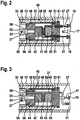
- FIG. 1 illustrated Druckmessglühkerze combines a conventional glow plug 20 for use in auto-ignition internal combustion engine with an additional pressure measurement function of a pressure measuring device 30 for detecting a combustion chamber pressure of the internal combustion engine.
- the pressure measuring glow plug essentially comprises an annealing and pressure measuring module 11, which is housed in a housing 13 of the Druckmessglühkerze, which is hereinafter referred to as Glühmodulgetude, and a non-illustrated connection module 14, which is housed in a terminal module housing 15.
- connection module 14 two sensor connections 16 for the pressure measuring device 30 and a high-current connection 17 for the glow plug 20 are projecting into the glow module housing 13 and exposed there, which lead in the connection module 14 to not shown electrical connections for a connector.
- a signal processing unit for the preprocessing of the signals of the pressure measuring device 30 may be integrated.
- the components of the glow plug 20 for igniting the internal combustion engine and the components of the pressure measuring device 30 are housed for combustion chamber pressure measurement.
- the glow plug 20 comprises a glow plug 21 protruding from the glow plug housing 13 on the combustion chamber side, which protrudes with the projecting part into the combustion chamber of the internal combustion engine and thereby simultaneously forms a pressure sensor for the pressure prevailing in the combustion chamber.
- the glow plug 21 is in the present embodiment, a ceramic glow plug, in which an unillustrated electrical heating element is embedded.
- the ceramic glow plug 21 is surrounded by a metallic support tube 22.
- the heating element is connected to form a pole via an external contact with the support tube 22 and the formation of the other pole via an electrical connection 23 with a GlühstromWallet 24, wherein the GlühstromWallet 24 exposed as a solid terminal bolt with a side facing away from the combustion chamber end portion 25 is led out of the support tube 22.
- the electrical connection from the GlühstromWallet 24 to the high current terminal 17 on the connection module 12 is realized by means of a Glühstromtechnisch 27.
- an electrically insulating sealing element 29 is further arranged between support tube 22 and glow current contact 24, an electrically insulating sealing element 29 is further arranged.
- the glow plug 21 is also conceivable to perform the glow plug 21 as a metallic glow tube with an embedded heating coil.
- the pressure measuring device 30 is accommodated within the glow module housing 13 and comprises a sensor unit 40, a flexurally elastic membrane 32, a sensor housing 33 and a connecting sleeve 34.
- the sensor unit 40 comprises a piezoelectric pressure sensor 41, a glow pin side pressure piece 42, a support element side pressure piece 43, a pressure transmission piece 44, a support member 45 and a clamping sleeve 46.
- the clamping sleeve 46 is resilient in order to realize an axial movement of the pressure transmission piece 44 for the transmission of force to the pressure sensor 41 educated.
- the clamping sleeve 46 is designed for example as a tubular spring.
- the pressure pieces 41, 42 are made of an electrically insulating material.
- the pressure sensor 41 is between the glow pin side pressure piece 42 and the support member side pressure piece 43 by means of a biasing force, by the clamping sleeve 46 is applied, positioned.
- the pressure sensor 41 has two sensor lines 47, which are electrically connected to the two sensor terminals 16.
- the pressure transmission piece 44 and the support member 45 are connected by means of the resilient clamping sleeve 46, such that on the one hand acts on the pressure sensor 41, the required bias and on the other hand, the pressure transmission piece 44 can perform the necessary for the transmission of force to the pressure sensor 41 axial movement.
- the clamping sleeve 46 forms a separate clamping element for the pressure sensor 41 independently of the sensor housing 33.
- the clamping sleeve 46 is connected to the pressure transmission piece 44 by means of a first weld 48 and the support member 45 by means of a second weld 49.
- the sensor unit 40 forms a unit that can be preassembled separately from the annealing and pressure measuring module 11.
- the sensor lines 47 are led out of the sensor unit 40 on the connection module side. These are in accordance with FIG. 2 in the support member 45, two passages 51 are provided, through which the two sensor lines 47 are guided to the sensor terminals 16 out.
- the Glühstrom endeavor 27 is guided by the sensor unit 40.
- the pressure transfer piece 44 has a first passage 52 for passing the Glühstromtechnisch 27 for GlühstromWallet 24 out and the support member 45 a second passage 53 for passing the Glühstrom réelle 27 to the high-current terminal 17 toward.
- the Glühstrom réelle 27 guided substantially axially through the sensor unit 30 has a first 90 degree bend on the glow plug side and a second 90 degree bend on the connection side, so that the glow current line 27 can be guided axially through the sensor unit 40.
- a radial bore is introduced into the connection-side end portion 25 of the GlühstromWallets 24, in which the first 90-degree bend of Glühstromtechnisch 27 introduced and contacted there is electrically.
- the glow plug 21 is mounted axially displaceably in the glow module housing 13 by means of the flexurally elastic diaphragm 32. Furthermore, there is a power transmission from the glow plug 21 to the pressure transmission piece 44 of the sensor unit 40 instead.
- the support tube 22 fixedly connected to the glow plug 21 is extended with the connection sleeve 34 axially in the direction of the sensor unit 40 with an end section 55.
- the extended end portion 55 is placed on a formed on the pressure transmitting piece 44 collar and connected there by means of a first weld 56 with the pressure transmitting piece 44.
- the support tube 22 and the connecting sleeve 34 are firmly connected by means of a second weld seam 57.
- Within the end portion 55 thus forms a wood-cylindrical receiving space 58, in which the connection-side end portion 25 of the Glühstromnaps 24 is exposed and contacted there with the Glühstrom effet 27.
- the flexurally elastic membrane 32 is connected to the sensor housing 33 by means of a third weld seam 59.
- the sensor housing 33 is welded to the support element 45 by means of a fourth weld 61.
- the second weld 49 for connecting the clamping sleeve 46 and the fourth weld 61 for connecting the Sensorgeophüses 33 are performed at different diameters of the support member 45.
- annular gap 36 serves to provide a friction-free distance for the axial displacement of the connecting sleeve 34 and the resilient clamping sleeve 34 relative to the housing-fixed sensor housing 33.
- an outer support portion 64 is formed on the sensor housing 33, which is adapted to the outer diameter of the glow module housing 13 with the outer diameter is.
- the support portion 64 forms a connection point on the sensor housing 13, with which the sensor housing 33 is connected to the glow module housing 13 by means of another weld 62.
- the further weld 62 and the third weld 59 are designed to seal circumferentially.
- the bias voltage for the pressure sensor 41 is thus applied by the clamping sleeve 46 and not by the spring force of the flexurally elastic membrane 32.
- the bias for the pressure sensor 41 outside the annealing and pressure measuring module 11 on the preassembled sensor unit 40 is adjustable.
- the bias of the pressure sensor 41 is thereby not influenced by the spring force of the resilient membrane 32 and also not by the subsequent assembly steps in the insertion of the annealing and pressure measuring module 11 in the Glühmodulgephase 13.
- the prevailing pressure in the combustion chamber which exerts a compressive force acting as a pressure transducer glow plug 21 causes due to the flexurally elastic membrane 32 of the glow plug 21 with the support tube 22 and the connecting sleeve 34 an axial movement relative to the firmly fixed in the cylinder head Glühmodulgephaseuse 13 along the Longitudinal axis of the Druckmessglühkerze performs.
- the pressure force acts on the pressure transmission piece 44 and this presses due to the elastic effect of the clamping sleeve 46 via the first pressure piece 42 on the pressure sensor 41, which is supported via the second pressure piece 43 on the fixedly connected to the sensor housing 33 and thereby fixed support member 45.
Landscapes
- Engineering & Computer Science (AREA)
- Chemical & Material Sciences (AREA)
- Combustion & Propulsion (AREA)
- Mechanical Engineering (AREA)
- General Engineering & Computer Science (AREA)
- Measuring Fluid Pressure (AREA)
Claims (7)
- Bougie de préchauffage avec mesure de pression, comprenant un boîtier (13), dans lequel sont disposés un crayon de préchauffage (21) pour l'allumage d'un mélange comburant dans une chambre de combustion d'un moteur à combustion interne et un dispositif de mesure de pression (30) avec un capteur de pression (41) pour détecter une pression dans la chambre de combustion du moteur à combustion interne, le crayon de préchauffage (21) agissant en tant que capteur de pression étant raccordé par le biais d'une membrane flexible élastique (32) au boîtier (13), la force agissant dans la chambre de combustion sur le crayon de préchauffage (21) étant transmise au capteur de pression (41), le capteur de pression (41) étant disposé au moyen d'une force de précontrainte entre un élément de transfert de pression (44) et un élément de support (45), et l'élément de support (45) étant fixé au boîtier du module de préchauffage (13) de manière fixée au boîtier par le biais d'un boîtier de capteur (33), un manchon de serrage (46) étant prévu pour appliquer la force de précontrainte pour le capteur de pression (41), lequel manchon de serrage est raccordé par une extrémité à l'élément de transfert de pression (44) et par l'autre extrémité à l'élément de support (45), caractérisée en ce que le manchon de serrage (46), l'élément de transfert de pression (44), l'élément de support (44) ainsi que le capteur de pression (41) entouré par ceux-ci constituent une unité de capteur prémontée (40), et en ce que l'unité de capteur prémontée (40) peut être insérée dans le boîtier de capteur (33) au niveau d'une portion d'extrémité éloignée de la chambre de combustion, le boîtier de capteur (33) est raccordé à l'élément de support (45) par une portion d'extrémité éloignée de la chambre de combustion, et le raccordement du manchon de serrage (46) et le raccordement du boîtier de capteur (33) étant réalisés sur des diamètres différents de l'élément de support (45).
- Bougie de préchauffage avec mesure de pression selon la revendication 1, caractérisée en ce que le boîtier de capteur (33) est connecté à la membrane flexible élastique (32) au niveau d'une portion d'extrémité tournée vers la chambre de combustion.
- Bougie de préchauffage avec mesure de pression selon la revendication 1 ou 2, caractérisée en ce que le boîtier de capteur (33) est connecté fixement au boîtier (13) au moyen d'une zone de fixation.
- Bougie de préchauffage avec mesure de pression selon la revendication 3, caractérisée en ce qu'une portion de support (64) est réalisée au niveau du boîtier de capteur (33), laquelle forme la zone de fixation pour la fixation au boîtier (13).
- Bougie de préchauffage avec mesure de pression selon la revendication 1, caractérisée en ce qu'un manchon de raccordement (34) est bridé sur l'élément de transfert de pression (44), lequel manchon est raccordé au moins indirectement au crayon de préchauffage (21).
- Bougie de préchauffage avec mesure de pression selon la revendication 5, caractérisée en ce que le manchon de raccordement (34) constitue du côté du crayon de préchauffage un espace de réception (58) pour un contact du courant de préchauffage (24), dans lequel le contact du courant de préchauffage (24) est mis en contact au moyen d'une ligne de courant de préchauffage (28).
- Bougie de préchauffage avec mesure de pression selon la revendication 6, caractérisée en ce que l'élément de transfert de pression (44) présente un premier passage (52) et l'élément de support (45) présente un deuxième passage (53) pour la ligne de courant de préchauffage (28), de telle sorte que la ligne de courant de préchauffage (28) soit guidée à travers l'unité de capteur (40) et puisse être mise en contact avec un raccord à courant fort (17) situé à l'extérieur de l'unité de capteur (40).
Applications Claiming Priority (2)
| Application Number | Priority Date | Filing Date | Title |
|---|---|---|---|
| DE102012209237A DE102012209237A1 (de) | 2012-05-31 | 2012-05-31 | Druckmessglühkerze |
| PCT/EP2013/058958 WO2013178416A1 (fr) | 2012-05-31 | 2013-04-30 | Bougie de préchauffage à mesure de pression |
Publications (2)
| Publication Number | Publication Date |
|---|---|
| EP2856035A1 EP2856035A1 (fr) | 2015-04-08 |
| EP2856035B1 true EP2856035B1 (fr) | 2016-12-14 |
Family
ID=48190524
Family Applications (1)
| Application Number | Title | Priority Date | Filing Date |
|---|---|---|---|
| EP13718861.1A Not-in-force EP2856035B1 (fr) | 2012-05-31 | 2013-04-30 | Bougie de préchauffage avec capteur de pression |
Country Status (7)
| Country | Link |
|---|---|
| US (1) | US9874195B2 (fr) |
| EP (1) | EP2856035B1 (fr) |
| JP (1) | JP5890938B2 (fr) |
| CN (1) | CN104508379B (fr) |
| DE (1) | DE102012209237A1 (fr) |
| IN (1) | IN2014DN09912A (fr) |
| WO (1) | WO2013178416A1 (fr) |
Families Citing this family (7)
| Publication number | Priority date | Publication date | Assignee | Title |
|---|---|---|---|---|
| DE102015114811A1 (de) | 2015-09-04 | 2017-03-09 | Borgwarner Ludwigsburg Gmbh | Druckmessglühkerze |
| DE102015224166A1 (de) | 2015-12-03 | 2017-06-08 | Robert Bosch Gmbh | Sensorhalter für eine Druckmessglühkerze einer Brennkraftmaschine |
| DE102015224169A1 (de) | 2015-12-03 | 2017-06-08 | Robert Bosch Gmbh | Sensorhalter für eine Druckmessglühkerze einer Brennkraftmaschine |
| DE102015224168A1 (de) | 2015-12-03 | 2017-06-08 | Robert Bosch Gmbh | Vorrichtung zum Erfassen eines Brennraumdrucks in einem Brennraum einer Brennkraftmaschine |
| JP6686673B2 (ja) | 2016-04-27 | 2020-04-22 | 株式会社デンソー | 歪み検出センサ |
| DE102016114929B4 (de) * | 2016-08-11 | 2018-05-09 | Borgwarner Ludwigsburg Gmbh | Druckmessglühkerze |
| CN114323661A (zh) * | 2022-03-07 | 2022-04-12 | 江铃汽车股份有限公司 | 发动机缸内燃烧噪声测试分析方法及系统 |
Family Cites Families (24)
| Publication number | Priority date | Publication date | Assignee | Title |
|---|---|---|---|---|
| JP2559858Y2 (ja) * | 1992-12-09 | 1998-01-19 | 日本特殊陶業株式会社 | 圧力センサ |
| JP3911930B2 (ja) * | 1999-10-28 | 2007-05-09 | 株式会社デンソー | 燃焼圧センサ付きグロープラグ |
| JP3912352B2 (ja) | 2002-10-07 | 2007-05-09 | 株式会社デンソー | 燃焼圧センサ付きグロープラグ |
| DE10343521A1 (de) * | 2003-09-19 | 2005-04-21 | Beru Ag | Druckmessglühkerze für einen Dieselmotor |
| JP4708711B2 (ja) * | 2004-02-03 | 2011-06-22 | 株式会社デンソー | 圧力センサ |
| EP1637806B1 (fr) * | 2004-09-15 | 2012-02-01 | Beru AG | Bougie de préchauffage avec capteur de pression pour moteur diesel |
| JP4903165B2 (ja) * | 2005-02-24 | 2012-03-28 | キストラー ホールディング アクチエンゲゼルシャフト | 電気絶縁皮膜によって保持された圧電式力センサ用部品又は圧電式圧力センサ用部品 |
| DE102005016463A1 (de) * | 2005-04-11 | 2006-10-12 | Robert Bosch Gmbh | Glühstiftkerze mit integriertem Druckmesselement |
| FR2884299B1 (fr) * | 2005-04-12 | 2007-06-29 | Siemens Vdo Automotive Sas | Bougie de prechauffage a capteur de pression integre et corps d'une telle bougie de prechauffage |
| DE102005035062A1 (de) | 2005-07-27 | 2007-02-15 | Robert Bosch Gmbh | Vorrichtung zur Erfassung des Brennraumdrucks einer Brennkraftmaschine |
| DE102006008639A1 (de) * | 2005-12-23 | 2007-06-28 | Robert Bosch Gmbh | Glühstiftkerze |
| DE102006008351A1 (de) | 2006-02-21 | 2007-08-23 | Robert Bosch Gmbh | Druckmesseinrichtung |
| DE102006008350A1 (de) * | 2006-02-21 | 2007-08-30 | Robert Bosch Gmbh | Druckmesseinrichtung |
| DE102006049079A1 (de) * | 2006-10-13 | 2008-04-17 | Robert Bosch Gmbh | Druckmesseinrichtung |
| DE102007049971A1 (de) * | 2007-10-18 | 2009-04-23 | Robert Bosch Gmbh | Glühstiftkerze |
| DE102008017110B3 (de) * | 2008-04-02 | 2009-09-10 | Beru Ag | Druckmessglühkerze |
| DE102008020509B4 (de) * | 2008-04-23 | 2010-02-25 | Beru Ag | Verfahren zur Herstellung einer Vorrichtung zur Ermittlung des Brennraumdrucks und eine solche Vorrichtung |
| US8205490B2 (en) * | 2008-06-04 | 2012-06-26 | Kistler Holding Ag | Pressure sensor for measurements in a chamber of an internal combustion engine |
| EP2138820B1 (fr) * | 2008-06-25 | 2016-09-21 | Sensata Technologies, Inc. | Fiche de mesure de la pression piézorésistante pour un moteur à combustion |
| US8217309B2 (en) * | 2008-12-15 | 2012-07-10 | Federal-Mogul Italy Srl. | Glow plug with pressure sensing canister |
| US8068558B2 (en) * | 2008-12-17 | 2011-11-29 | Nortel Networks Limited | Selective peak power reduction |
| DE102010038798A1 (de) * | 2010-08-02 | 2012-02-02 | Robert Bosch Gmbh | Vorrichtung zur Erfassung eines Brennraumdrucks |
| DE102011002596A1 (de) * | 2011-01-12 | 2012-07-12 | Robert Bosch Gmbh | Brennraumdrucksensor zur Erfassung eines Drucks in einem Brennraum einer Verbrennungskraftmaschine |
| WO2012115080A1 (fr) * | 2011-02-25 | 2012-08-30 | 日本特殊陶業株式会社 | Bougie de préchauffage à capteur de pression de combustion |
-
2012
- 2012-05-31 DE DE102012209237A patent/DE102012209237A1/de not_active Withdrawn
-
2013
- 2013-04-30 CN CN201380040354.2A patent/CN104508379B/zh not_active Expired - Fee Related
- 2013-04-30 US US14/404,486 patent/US9874195B2/en not_active Expired - Fee Related
- 2013-04-30 EP EP13718861.1A patent/EP2856035B1/fr not_active Not-in-force
- 2013-04-30 IN IN9912DEN2014 patent/IN2014DN09912A/en unknown
- 2013-04-30 JP JP2015514396A patent/JP5890938B2/ja not_active Expired - Fee Related
- 2013-04-30 WO PCT/EP2013/058958 patent/WO2013178416A1/fr not_active Ceased
Non-Patent Citations (1)
| Title |
|---|
| None * |
Also Published As
| Publication number | Publication date |
|---|---|
| CN104508379A (zh) | 2015-04-08 |
| CN104508379B (zh) | 2016-12-21 |
| US20150136054A1 (en) | 2015-05-21 |
| US9874195B2 (en) | 2018-01-23 |
| DE102012209237A1 (de) | 2013-12-05 |
| IN2014DN09912A (fr) | 2015-08-14 |
| JP5890938B2 (ja) | 2016-03-22 |
| WO2013178416A1 (fr) | 2013-12-05 |
| EP2856035A1 (fr) | 2015-04-08 |
| JP2015525334A (ja) | 2015-09-03 |
Similar Documents
| Publication | Publication Date | Title |
|---|---|---|
| WO2013178416A1 (fr) | Bougie de préchauffage à mesure de pression | |
| EP1989485B1 (fr) | Dispositif de mesure de la pression | |
| EP2812635B1 (fr) | Bougie de préchauffage à mesure de pression | |
| EP2102620B1 (fr) | Dispositif de mesure de pression | |
| EP1794500B1 (fr) | Bougie avec crayon de prechauffage a montage elastique | |
| EP1364123B1 (fr) | Dispositif de fixation | |
| EP1517086A1 (fr) | Bougie d'allumage avec un capteur de pression pour un moteur Diesel | |
| EP1989524A1 (fr) | Dispositif de mesure de la pression | |
| EP2223066A2 (fr) | Composant pour mesurer une force ou une pression et capteur comprenant un tel composant | |
| EP1967834B1 (fr) | Bougie d'allumage avec un capteur de mesure de pression | |
| EP2601497A1 (fr) | Dispositif pour détecter une pression de chambre de combustion d'un moteur à combustion interne | |
| EP2791581B1 (fr) | Bougie de préchauffage munie d'un capteur de pression | |
| DE102004043874A1 (de) | Vorrichtung zur Erfassung des Drucks in einem Brennraum einer Verbrennungskraftmaschine | |
| EP2080002A2 (fr) | Dispositif de mesure de pression | |
| EP1834342A1 (fr) | Dispositif d'insertion d'un cable d'alimentation electrique | |
| EP1875135B1 (fr) | Bougie de préchauffage comprenant un capteur de pression de chambre de combustion et un élement d'étanchéité | |
| WO2013087506A1 (fr) | Dispositif de mesure de pression, en particulier bougie de préchauffage à mesure de pression | |
| EP2702378A1 (fr) | Dispositif pour détecter une pression, en particulier une pression de chambre de combustion d'un moteur à combustion interne | |
| EP3384264B1 (fr) | Procédé de fabrication d'un dispositif de détection d'au moins une caractéristique d'un milieu fluide dans une chambre de mesure | |
| WO2014067722A1 (fr) | Capteur de pression de chambre de combustion miniaturisé comprenant un boîtier de capteur précontraint en traction | |
| WO2006128755A1 (fr) | Capteur de pression de chambre de combustion integre | |
| WO2005114054A1 (fr) | Bougie crayon de prechauffage a capteur de pression integre | |
| EP2702379A1 (fr) | Dispositif pour détecter une pression, en particulier une pression de chambre de combustion d'un moteur à combustion interne | |
| EP2884093A1 (fr) | Dispositif de détection destiné à détecter la pression ou la force, procédé de fabrication d'un dispositif de détection et injecteur de carburant doté d'un dispositif de détection | |
| DE102005039548A1 (de) | Piezoaktor mit einer Steckverbindung |
Legal Events
| Date | Code | Title | Description |
|---|---|---|---|
| PUAI | Public reference made under article 153(3) epc to a published international application that has entered the european phase |
Free format text: ORIGINAL CODE: 0009012 |
|
| 17P | Request for examination filed |
Effective date: 20150105 |
|
| AK | Designated contracting states |
Kind code of ref document: A1 Designated state(s): AL AT BE BG CH CY CZ DE DK EE ES FI FR GB GR HR HU IE IS IT LI LT LU LV MC MK MT NL NO PL PT RO RS SE SI SK SM TR |
|
| AX | Request for extension of the european patent |
Extension state: BA ME |
|
| DAX | Request for extension of the european patent (deleted) | ||
| REG | Reference to a national code |
Ref country code: DE Ref legal event code: R079 Ref document number: 502013005738 Country of ref document: DE Free format text: PREVIOUS MAIN CLASS: F23Q0007000000 Ipc: F02P0019020000 |
|
| RIC1 | Information provided on ipc code assigned before grant |
Ipc: F02P 19/02 20060101AFI20160719BHEP Ipc: F23Q 7/00 20060101ALI20160719BHEP |
|
| GRAP | Despatch of communication of intention to grant a patent |
Free format text: ORIGINAL CODE: EPIDOSNIGR1 |
|
| INTG | Intention to grant announced |
Effective date: 20160902 |
|
| GRAS | Grant fee paid |
Free format text: ORIGINAL CODE: EPIDOSNIGR3 |
|
| GRAA | (expected) grant |
Free format text: ORIGINAL CODE: 0009210 |
|
| AK | Designated contracting states |
Kind code of ref document: B1 Designated state(s): AL AT BE BG CH CY CZ DE DK EE ES FI FR GB GR HR HU IE IS IT LI LT LU LV MC MK MT NL NO PL PT RO RS SE SI SK SM TR |
|
| REG | Reference to a national code |
Ref country code: GB Ref legal event code: FG4D Free format text: NOT ENGLISH |
|
| REG | Reference to a national code |
Ref country code: CH Ref legal event code: EP |
|
| REG | Reference to a national code |
Ref country code: IE Ref legal event code: FG4D Free format text: LANGUAGE OF EP DOCUMENT: GERMAN |
|
| REG | Reference to a national code |
Ref country code: AT Ref legal event code: REF Ref document number: 853828 Country of ref document: AT Kind code of ref document: T Effective date: 20170115 |
|
| REG | Reference to a national code |
Ref country code: DE Ref legal event code: R096 Ref document number: 502013005738 Country of ref document: DE |
|
| PG25 | Lapsed in a contracting state [announced via postgrant information from national office to epo] |
Ref country code: LV Free format text: LAPSE BECAUSE OF FAILURE TO SUBMIT A TRANSLATION OF THE DESCRIPTION OR TO PAY THE FEE WITHIN THE PRESCRIBED TIME-LIMIT Effective date: 20161214 |
|
| REG | Reference to a national code |
Ref country code: LT Ref legal event code: MG4D |
|
| REG | Reference to a national code |
Ref country code: NL Ref legal event code: MP Effective date: 20161214 |
|
| REG | Reference to a national code |
Ref country code: FR Ref legal event code: PLFP Year of fee payment: 5 |
|
| PG25 | Lapsed in a contracting state [announced via postgrant information from national office to epo] |
Ref country code: NO Free format text: LAPSE BECAUSE OF FAILURE TO SUBMIT A TRANSLATION OF THE DESCRIPTION OR TO PAY THE FEE WITHIN THE PRESCRIBED TIME-LIMIT Effective date: 20170314 Ref country code: GR Free format text: LAPSE BECAUSE OF FAILURE TO SUBMIT A TRANSLATION OF THE DESCRIPTION OR TO PAY THE FEE WITHIN THE PRESCRIBED TIME-LIMIT Effective date: 20170315 Ref country code: LT Free format text: LAPSE BECAUSE OF FAILURE TO SUBMIT A TRANSLATION OF THE DESCRIPTION OR TO PAY THE FEE WITHIN THE PRESCRIBED TIME-LIMIT Effective date: 20161214 Ref country code: SE Free format text: LAPSE BECAUSE OF FAILURE TO SUBMIT A TRANSLATION OF THE DESCRIPTION OR TO PAY THE FEE WITHIN THE PRESCRIBED TIME-LIMIT Effective date: 20161214 |
|
| PG25 | Lapsed in a contracting state [announced via postgrant information from national office to epo] |
Ref country code: HR Free format text: LAPSE BECAUSE OF FAILURE TO SUBMIT A TRANSLATION OF THE DESCRIPTION OR TO PAY THE FEE WITHIN THE PRESCRIBED TIME-LIMIT Effective date: 20161214 Ref country code: RS Free format text: LAPSE BECAUSE OF FAILURE TO SUBMIT A TRANSLATION OF THE DESCRIPTION OR TO PAY THE FEE WITHIN THE PRESCRIBED TIME-LIMIT Effective date: 20161214 Ref country code: FI Free format text: LAPSE BECAUSE OF FAILURE TO SUBMIT A TRANSLATION OF THE DESCRIPTION OR TO PAY THE FEE WITHIN THE PRESCRIBED TIME-LIMIT Effective date: 20161214 |
|
| PG25 | Lapsed in a contracting state [announced via postgrant information from national office to epo] |
Ref country code: NL Free format text: LAPSE BECAUSE OF FAILURE TO SUBMIT A TRANSLATION OF THE DESCRIPTION OR TO PAY THE FEE WITHIN THE PRESCRIBED TIME-LIMIT Effective date: 20161214 |
|
| PG25 | Lapsed in a contracting state [announced via postgrant information from national office to epo] |
Ref country code: IS Free format text: LAPSE BECAUSE OF FAILURE TO SUBMIT A TRANSLATION OF THE DESCRIPTION OR TO PAY THE FEE WITHIN THE PRESCRIBED TIME-LIMIT Effective date: 20170414 Ref country code: EE Free format text: LAPSE BECAUSE OF FAILURE TO SUBMIT A TRANSLATION OF THE DESCRIPTION OR TO PAY THE FEE WITHIN THE PRESCRIBED TIME-LIMIT Effective date: 20161214 Ref country code: CZ Free format text: LAPSE BECAUSE OF FAILURE TO SUBMIT A TRANSLATION OF THE DESCRIPTION OR TO PAY THE FEE WITHIN THE PRESCRIBED TIME-LIMIT Effective date: 20161214 Ref country code: RO Free format text: LAPSE BECAUSE OF FAILURE TO SUBMIT A TRANSLATION OF THE DESCRIPTION OR TO PAY THE FEE WITHIN THE PRESCRIBED TIME-LIMIT Effective date: 20161214 Ref country code: SK Free format text: LAPSE BECAUSE OF FAILURE TO SUBMIT A TRANSLATION OF THE DESCRIPTION OR TO PAY THE FEE WITHIN THE PRESCRIBED TIME-LIMIT Effective date: 20161214 |
|
| PG25 | Lapsed in a contracting state [announced via postgrant information from national office to epo] |
Ref country code: IT Free format text: LAPSE BECAUSE OF FAILURE TO SUBMIT A TRANSLATION OF THE DESCRIPTION OR TO PAY THE FEE WITHIN THE PRESCRIBED TIME-LIMIT Effective date: 20161214 Ref country code: PT Free format text: LAPSE BECAUSE OF FAILURE TO SUBMIT A TRANSLATION OF THE DESCRIPTION OR TO PAY THE FEE WITHIN THE PRESCRIBED TIME-LIMIT Effective date: 20170414 Ref country code: PL Free format text: LAPSE BECAUSE OF FAILURE TO SUBMIT A TRANSLATION OF THE DESCRIPTION OR TO PAY THE FEE WITHIN THE PRESCRIBED TIME-LIMIT Effective date: 20161214 Ref country code: ES Free format text: LAPSE BECAUSE OF FAILURE TO SUBMIT A TRANSLATION OF THE DESCRIPTION OR TO PAY THE FEE WITHIN THE PRESCRIBED TIME-LIMIT Effective date: 20161214 Ref country code: SM Free format text: LAPSE BECAUSE OF FAILURE TO SUBMIT A TRANSLATION OF THE DESCRIPTION OR TO PAY THE FEE WITHIN THE PRESCRIBED TIME-LIMIT Effective date: 20161214 Ref country code: BG Free format text: LAPSE BECAUSE OF FAILURE TO SUBMIT A TRANSLATION OF THE DESCRIPTION OR TO PAY THE FEE WITHIN THE PRESCRIBED TIME-LIMIT Effective date: 20170314 |
|
| REG | Reference to a national code |
Ref country code: DE Ref legal event code: R097 Ref document number: 502013005738 Country of ref document: DE |
|
| PLBE | No opposition filed within time limit |
Free format text: ORIGINAL CODE: 0009261 |
|
| STAA | Information on the status of an ep patent application or granted ep patent |
Free format text: STATUS: NO OPPOSITION FILED WITHIN TIME LIMIT |
|
| 26N | No opposition filed |
Effective date: 20170915 |
|
| PG25 | Lapsed in a contracting state [announced via postgrant information from national office to epo] |
Ref country code: DK Free format text: LAPSE BECAUSE OF FAILURE TO SUBMIT A TRANSLATION OF THE DESCRIPTION OR TO PAY THE FEE WITHIN THE PRESCRIBED TIME-LIMIT Effective date: 20161214 |
|
| REG | Reference to a national code |
Ref country code: CH Ref legal event code: PL |
|
| GBPC | Gb: european patent ceased through non-payment of renewal fee |
Effective date: 20170430 |
|
| REG | Reference to a national code |
Ref country code: IE Ref legal event code: MM4A |
|
| PG25 | Lapsed in a contracting state [announced via postgrant information from national office to epo] |
Ref country code: MC Free format text: LAPSE BECAUSE OF FAILURE TO SUBMIT A TRANSLATION OF THE DESCRIPTION OR TO PAY THE FEE WITHIN THE PRESCRIBED TIME-LIMIT Effective date: 20161214 |
|
| PG25 | Lapsed in a contracting state [announced via postgrant information from national office to epo] |
Ref country code: LI Free format text: LAPSE BECAUSE OF NON-PAYMENT OF DUE FEES Effective date: 20170430 Ref country code: SI Free format text: LAPSE BECAUSE OF FAILURE TO SUBMIT A TRANSLATION OF THE DESCRIPTION OR TO PAY THE FEE WITHIN THE PRESCRIBED TIME-LIMIT Effective date: 20161214 Ref country code: GB Free format text: LAPSE BECAUSE OF NON-PAYMENT OF DUE FEES Effective date: 20170430 Ref country code: CH Free format text: LAPSE BECAUSE OF NON-PAYMENT OF DUE FEES Effective date: 20170430 Ref country code: LU Free format text: LAPSE BECAUSE OF NON-PAYMENT OF DUE FEES Effective date: 20170430 |
|
| REG | Reference to a national code |
Ref country code: BE Ref legal event code: MM Effective date: 20170430 |
|
| REG | Reference to a national code |
Ref country code: FR Ref legal event code: PLFP Year of fee payment: 6 |
|
| PG25 | Lapsed in a contracting state [announced via postgrant information from national office to epo] |
Ref country code: IE Free format text: LAPSE BECAUSE OF NON-PAYMENT OF DUE FEES Effective date: 20170430 |
|
| PG25 | Lapsed in a contracting state [announced via postgrant information from national office to epo] |
Ref country code: BE Free format text: LAPSE BECAUSE OF NON-PAYMENT OF DUE FEES Effective date: 20170430 |
|
| PGFP | Annual fee paid to national office [announced via postgrant information from national office to epo] |
Ref country code: FR Payment date: 20180424 Year of fee payment: 6 |
|
| PG25 | Lapsed in a contracting state [announced via postgrant information from national office to epo] |
Ref country code: MT Free format text: LAPSE BECAUSE OF FAILURE TO SUBMIT A TRANSLATION OF THE DESCRIPTION OR TO PAY THE FEE WITHIN THE PRESCRIBED TIME-LIMIT Effective date: 20161214 |
|
| PGFP | Annual fee paid to national office [announced via postgrant information from national office to epo] |
Ref country code: DE Payment date: 20180627 Year of fee payment: 6 |
|
| REG | Reference to a national code |
Ref country code: AT Ref legal event code: MM01 Ref document number: 853828 Country of ref document: AT Kind code of ref document: T Effective date: 20180430 |
|
| PG25 | Lapsed in a contracting state [announced via postgrant information from national office to epo] |
Ref country code: HU Free format text: LAPSE BECAUSE OF FAILURE TO SUBMIT A TRANSLATION OF THE DESCRIPTION OR TO PAY THE FEE WITHIN THE PRESCRIBED TIME-LIMIT; INVALID AB INITIO Effective date: 20130430 |
|
| PG25 | Lapsed in a contracting state [announced via postgrant information from national office to epo] |
Ref country code: CY Free format text: LAPSE BECAUSE OF FAILURE TO SUBMIT A TRANSLATION OF THE DESCRIPTION OR TO PAY THE FEE WITHIN THE PRESCRIBED TIME-LIMIT Effective date: 20161214 Ref country code: AT Free format text: LAPSE BECAUSE OF NON-PAYMENT OF DUE FEES Effective date: 20180430 |
|
| REG | Reference to a national code |
Ref country code: DE Ref legal event code: R119 Ref document number: 502013005738 Country of ref document: DE |
|
| PG25 | Lapsed in a contracting state [announced via postgrant information from national office to epo] |
Ref country code: MK Free format text: LAPSE BECAUSE OF FAILURE TO SUBMIT A TRANSLATION OF THE DESCRIPTION OR TO PAY THE FEE WITHIN THE PRESCRIBED TIME-LIMIT Effective date: 20161214 |
|
| PG25 | Lapsed in a contracting state [announced via postgrant information from national office to epo] |
Ref country code: DE Free format text: LAPSE BECAUSE OF NON-PAYMENT OF DUE FEES Effective date: 20191101 |
|
| PG25 | Lapsed in a contracting state [announced via postgrant information from national office to epo] |
Ref country code: FR Free format text: LAPSE BECAUSE OF NON-PAYMENT OF DUE FEES Effective date: 20190430 |
|
| PG25 | Lapsed in a contracting state [announced via postgrant information from national office to epo] |
Ref country code: TR Free format text: LAPSE BECAUSE OF FAILURE TO SUBMIT A TRANSLATION OF THE DESCRIPTION OR TO PAY THE FEE WITHIN THE PRESCRIBED TIME-LIMIT Effective date: 20161214 |
|
| PG25 | Lapsed in a contracting state [announced via postgrant information from national office to epo] |
Ref country code: AL Free format text: LAPSE BECAUSE OF FAILURE TO SUBMIT A TRANSLATION OF THE DESCRIPTION OR TO PAY THE FEE WITHIN THE PRESCRIBED TIME-LIMIT Effective date: 20161214 |