EP2856046B1 - Automatische herunterfahrsysteme für kühlfahrzeuge - Google Patents
Automatische herunterfahrsysteme für kühlfahrzeuge Download PDFInfo
- Publication number
- EP2856046B1 EP2856046B1 EP13739303.9A EP13739303A EP2856046B1 EP 2856046 B1 EP2856046 B1 EP 2856046B1 EP 13739303 A EP13739303 A EP 13739303A EP 2856046 B1 EP2856046 B1 EP 2856046B1
- Authority
- EP
- European Patent Office
- Prior art keywords
- sensor
- controller
- automatically
- container
- exhaust fan
- Prior art date
- Legal status (The legal status is an assumption and is not a legal conclusion. Google has not performed a legal analysis and makes no representation as to the accuracy of the status listed.)
- Active
Links
Images


Classifications
-
- F—MECHANICAL ENGINEERING; LIGHTING; HEATING; WEAPONS; BLASTING
- F25—REFRIGERATION OR COOLING; COMBINED HEATING AND REFRIGERATION SYSTEMS; HEAT PUMP SYSTEMS; MANUFACTURE OR STORAGE OF ICE; LIQUEFACTION SOLIDIFICATION OF GASES
- F25D—REFRIGERATORS; COLD ROOMS; ICE-BOXES; COOLING OR FREEZING APPARATUS NOT OTHERWISE PROVIDED FOR
- F25D29/00—Arrangement or mounting of control or safety devices
-
- F—MECHANICAL ENGINEERING; LIGHTING; HEATING; WEAPONS; BLASTING
- F25—REFRIGERATION OR COOLING; COMBINED HEATING AND REFRIGERATION SYSTEMS; HEAT PUMP SYSTEMS; MANUFACTURE OR STORAGE OF ICE; LIQUEFACTION SOLIDIFICATION OF GASES
- F25D—REFRIGERATORS; COLD ROOMS; ICE-BOXES; COOLING OR FREEZING APPARATUS NOT OTHERWISE PROVIDED FOR
- F25D11/00—Self-contained movable devices, e.g. domestic refrigerators
- F25D11/003—Transport containers
-
- F—MECHANICAL ENGINEERING; LIGHTING; HEATING; WEAPONS; BLASTING
- F25—REFRIGERATION OR COOLING; COMBINED HEATING AND REFRIGERATION SYSTEMS; HEAT PUMP SYSTEMS; MANUFACTURE OR STORAGE OF ICE; LIQUEFACTION SOLIDIFICATION OF GASES
- F25B—REFRIGERATION MACHINES, PLANTS OR SYSTEMS; COMBINED HEATING AND REFRIGERATION SYSTEMS; HEAT PUMP SYSTEMS
- F25B49/00—Arrangement or mounting of control or safety devices
- F25B49/02—Arrangement or mounting of control or safety devices for compression type machines, plants or systems
-
- B—PERFORMING OPERATIONS; TRANSPORTING
- B64—AIRCRAFT; AVIATION; COSMONAUTICS
- B64D—EQUIPMENT FOR FITTING IN OR TO AIRCRAFT; FLIGHT SUITS; PARACHUTES; ARRANGEMENT OR MOUNTING OF POWER PLANTS OR PROPULSION TRANSMISSIONS IN AIRCRAFT
- B64D13/00—Arrangements or adaptations of air-treatment apparatus for aircraft crew or passengers, or freight space
-
- F—MECHANICAL ENGINEERING; LIGHTING; HEATING; WEAPONS; BLASTING
- F25—REFRIGERATION OR COOLING; COMBINED HEATING AND REFRIGERATION SYSTEMS; HEAT PUMP SYSTEMS; MANUFACTURE OR STORAGE OF ICE; LIQUEFACTION SOLIDIFICATION OF GASES
- F25B—REFRIGERATION MACHINES, PLANTS OR SYSTEMS; COMBINED HEATING AND REFRIGERATION SYSTEMS; HEAT PUMP SYSTEMS
- F25B2600/00—Control issues
- F25B2600/02—Compressor control
- F25B2600/025—Compressor control by controlling speed
- F25B2600/0251—Compressor control by controlling speed with on-off operation
-
- F—MECHANICAL ENGINEERING; LIGHTING; HEATING; WEAPONS; BLASTING
- F25—REFRIGERATION OR COOLING; COMBINED HEATING AND REFRIGERATION SYSTEMS; HEAT PUMP SYSTEMS; MANUFACTURE OR STORAGE OF ICE; LIQUEFACTION SOLIDIFICATION OF GASES
- F25B—REFRIGERATION MACHINES, PLANTS OR SYSTEMS; COMBINED HEATING AND REFRIGERATION SYSTEMS; HEAT PUMP SYSTEMS
- F25B2600/00—Control issues
- F25B2600/11—Fan speed control
- F25B2600/111—Fan speed control of condenser fans
Definitions
- the disclosure is directed to automatic shutdown systems for use with refrigerated air cargo containers comprising a refrigeration system, which comprise in turn at least one exhaust fan.
- a refrigeration system which comprise in turn at least one exhaust fan.
- One or more sensors are located in and/or on the air cargo containers such that when air transit is detected by the one or more sensors, the shutdown system may automatically do one or more of the following: turn off the at least one exhaust fan; restrict the airflow from the at least one exhaust fan; and/or turn the refrigeration system off.
- temperature-controlled cargo containers are utilized to ship temperature sensitive items, for example, blood, plasma and vaccines.
- the interior temperature of the cargo container is maintained using a refrigeration system.
- Refrigeration systems typically comprise a refrigeration compressor, a refrigeration condenser, and exhaust fans.
- Exhaust fans may operate to remove heat from the interior of a refrigerated cargo container such as for example, by directing airflow over a condenser and exhausting the air to the external environment. Under normal operating conditions, the external direction of airflow is not an issue. However, when transported onboard an airplane, the flow of exhaust air and/or heat from the refrigerated cargo container may impair the ability of the airplane's smoke detection system to detect a smoke event and to alert the crew of an emergency. Further, in the event that an airplane's fire suppression system is activated, air currents generated by exhaust airflow from a refrigerated cargo container may impact the dispersal of the fire suppression agent, for example by changing the agent's concentration levels and therefore, its knockdown capabilities.
- fire signatures Once produced by a fire, fire signatures must travel to a detector to produce a response, such as an alert.
- cargo containers comprise smoke, relative humidity, temperature and/or particulate detectors which can reduce the speed of, or shutdown a container's exhaust fans when fire or smoke is detected.
- smoke, relative humidity, temperature and/or particulate detectors which can reduce the speed of, or shutdown a container's exhaust fans when fire or smoke is detected.
- combustibles, flammable liquids and/or electrical equipment may be present in the cargo hold of an airplane on any given flight. It stands to reason that a fire in an airplane may produce fire signatures beyond those that are detectable by the aforementioned detectors at the initiation of a fire.
- a shutdown system for use with a refrigerated cargo container that can quickly respond to a variety of fires and shutdown or restrict the container's exhaust airflow.
- a system that proactively shuts down or restricts the exhaust airflow when air transit is detected.
- a shutdown system that minimizes false alarms is desired.
- a shutdown system that does not require a user to initiate the shutdown or restriction of the container's exhaust airflow.
- EP 0 457 431 A2 describes a system adapted for removable placement in security enclosure fitted into the wall of a refrigerated container for respiring perishables, and for monitoring and controlling, continuously and dynamically, over a programmed, desired time, the concentration of oxygen, and the concentration of carbon dioxide, in such a container where the concentrations of these gases vary over time as the perishables respire.
- the system includes devices for sensing, separately, the concentrations of oxygen and carbon dioxide in the container, devices for establishing setpoints or desired values of oxygen and carbon dioxide concentration within the container, and for changing those setpoints, over time, depending on the nature of the perishable and other variables, and for maintaining the concentrations of oxygen and carbon dioxide at desired setpoints for desired programmed times by admitting air into the container, as a source of oxygen, and by scrubbing to remove carbon dioxide, as necessary.
- US 2007/289976 A1 describes a cargo container that includes an outer aluminum shell or housing having side, rear, bottom and top walls and a front opening with a pair of hinged doors.
- the housing receives a molded box-shaped composite outer shell which receives a molded box-shaped composite inner shell defining a cargo chamber.
- Corresponding walls of the inner and outer shells and the doors confine insulation cassettes each including vacuum insulation panels forming layers, all protected by plastic sheets and plastic film.
- Air is circulated by blowers within the chamber through a refrigeration evaporator and electrical heating elements, and a rear portion of the housing encloses operating components including a refrigeration compressor, storage batteries and exhaust fans.
- a control system senses temperature within the chamber and smoke and humidity outside the container and controls the operation of the compressor, exhaust fans and other components from storage batteries or an external power source.
- US 2004/226309 A1 describes a portable, temperature-controlled container for storing and transporting temperature-sensitive materials.
- the portable, temperature-controlled container includes a container having a bottom wall, four sides walls, and a top wall defining a cargo space.
- the container includes a temperature regulating unit connected to the container.
- the temperature regulating unit comprising a refrigeration unit.
- the temperature regulating unit being in communication with the cargo space of the container.
- the container includes a temperature controller connected to the container.
- the temperature controller comprising a temperature control unit and a temperature sensor positioned in the cargo space of the container.
- the container also includes a power supply.
- the temperature regulating unit can include a heating unit.
- US 5 058 390 A describes a vapor cycle cooling system which includes a compressor for compressing refrigerant vapor; a condenser receiving compressed refrigerant vapor from the compressor; a fan having at least two controllable speeds for blowing a fluid in contact with the condenser to remove heat from the compressed refrigerant at the condenser to cause the refrigerant to liquify, the speeds of the fan being controllable by a control signal; an expansion valve receiving liquid refrigerant from the condenser which expands the liquid refrigerant; an evaporator receiving the expanded refrigerant which exchanges heat with a fluid stream coupled to a heat load; and a controller for generating the control signal, responsive to a sensed evaporator temperature, a sensed ambient temperature and a sensed altitude which controls two speeds of the fan as a function of the sensed temperatures and altitude by generating the control signal.
- the unique solution that addresses the aforementioned needs may be employed in lieu of, or in conjunction with, one or more smoke detectors, particulate detectors, temperature sensors and relative humidity sensors, to automatically shut down or limit the power to the exhaust fans of a refrigerated cargo container in the event of a fire or air transit.
- the present disclosure is directed to two new automatic shutdown systems, an active shutdown system and a passive shutdown system.
- the active shutdown system monitors for fire signatures
- the passive shutdown system monitors for air transit
- the present invention is only directed to the passive shutdown system corresponding to the claims.
- the new automatic shutdown systems provide increased sensitivity to a wider variety of fire signatures and/or proactive management of the refrigerated cargo container's exhaust fans, so that fire damage may be mitigated.
- the active shutdown systems provide the additional advantage of detecting a variety of fire signatures such that fires arising from varying sources and combinations thereof may be detected. Moreover, by utilizing a number of sensors that detect different fire signatures, the active shutdown systems may reduce false alarms.
- the passive shutdown systems provide the additional advantage of being able to shut down the exhaust fans or to reduce the outflow of air prior to or during flight. These systems may be particularly useful for shipping cargo that can withstand the refrigeration unit either being turned off for the duration of a flight or being allowed to operate with restricted performance.
- a refrigerated cargo container comprises an automatic shutdown system that may be active, passive or a combination thereof.
- the automatic shutdown system comprises a sensor selected from the group of: a thermal imagery sensor; a gas sensor; an accelerometer; a light intensity sensor; an altimeter; a frequency sensor; an electrical signal noise sensor; a transponder signal receiver; a global positioning system; and combinations thereof.
- the automatic shutdown system further comprises a controller.
- the sensor is communicably attached to the controller, which is in turn, communicably attached to at least one of the exhaust fans that forms a part of the container's refrigeration system.
- the controller may be communicably attached to at least one air restrictor.
- the controller is arranged to automatically stop or automatically restrict airflow from the exhaust fan of the refrigeration system.
- a refrigerated cargo container comprises an active shutdown system.
- the active shutdown system may comprise one or more sensors in addition to, or in lieu of: a smoke detector; a particulate detector; a temperature sensor; a relative humidity sensor; and combinations thereof.
- the active shutdown system may comprise sensors selected from the group of: a thermal imagery sensor; a gas sensor; a light intensity sensor; and combinations thereof.
- the shutdown system further comprises a controller.
- the sensor is communicably attached to the controller, which is in turn, communicably attached to at least one of the exhaust fans that forms a part of the container's refrigeration system.
- the controller may be communicably attached to at least one air restrictor.
- the controller is arranged to automatically stop or automatically restrict airflow from the exhaust fan of the refrigeration system.
- a refrigerated cargo container comprises a passive shutdown system.
- the shutdown system comprises a sensor selected from the group of: an accelerometer; an altimeter; a frequency sensor; an electrical signal noise sensor; a transponder signal receiver; a global positioning system; and combinations thereof.
- the shutdown system further comprises a controller.
- the sensor is communicably attached to the controller, which is in turn, communicably attached to at least one of the exhaust fans that forms a part of the container's refrigeration system.
- the controller may be communicably attached to at least one air restrictor.
- the controller is arranged to automatically stop or automatically restrict airflow from the exhaust fan of the refrigeration system when air transit is detected by the at least one sensor, wherein air transit encompasses all phases of transport aboard an airplane including: loading onto the plane, takeoff, flight, landing and off-loading from the plane.
- the refrigeration system comprises exhaust fans.
- a sensor located in, on, or in connection with the container determines that air transit is occurring, the sensor sends a signal to a controller.
- the controller automatically restricts performance of the refrigeration system such as by automatically stopping or automatically restricting airflow from the exhaust fan. In some embodiments, this is achieved by cutting power to the refrigeration system, by cutting power to individual circuits which power the exhaust fan(s).
- the automatic method may further comprise the steps of a sensor detecting the change in altitude associated with an airplane takeoff or landing and communicating detection of the change in altitude to the controller.
- the controller then automatically restores performance of the refrigeration system such as by automatically increasing or automatically redirecting airflow from the exhaust fan to the outside of the container.
- sensor and “detector” are used interchangeably herein to refer to devices that detect parameters that may be associated with a fire or air transit.
- air transit encompasses all phases of transport aboard an airplane including, loading onto the plane, takeoff, flight, landing and off-loading from the plane.
- fire signature refers to one or more changes in the local environment of a fire. Fire signatures include, but are not limited to: smoke; change in temperature; change in light; particulate matter; change in energy; and combinations thereof.
- connection with means that the sensor may be disposed in an area that is remote from, i.e., not in or on, the refrigerated cargo container.
- restrictive refers to cessation, reduction or redirection of the airflow associated with at least one of the refrigeration system exhaust fans.
- airflow may include the flow of air and/or heat.
- system and methods described herein may comprise, consist of, or consist essentially of the elements and features of the disclosure described herein, as well as any additional or optional components, or features described herein or otherwise useful in a refrigerated cargo container safety system.
- the shutdown systems of the present disclosure are deployed on, in and/or in connection with a refrigerated cargo container.
- the shutdown systems may be active or passive and may comprise one or more sensors and a controller.
- Refrigerated cargo containers comprise a refrigeration system.
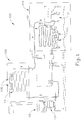
- Fig. 1 is a schematic representation of a typical refrigeration system 100.
- the depicted system comprises: a refrigeration compressor 101; a refrigeration condenser 102; condenser fans 103; a system controller 104; a user interface 105; a cold side compartment 106 for the product, which in turn comprises an evaporator 107 and internal fans 108; and a hot side compartment 109 with active components in ambient conditions, wherein the condenser fans 103 exhaust or vent air to the outside of the cargo container in which the refrigeration system is installed.
- Refrigeration systems may be disposed within a cargo container in any manner that is suitable for keeping its contents within a desired temperature range.
- cargo containers comprising refrigeration systems are disclosed in U.S. Patent Numbers 7,913,511 and 7,263,855 .
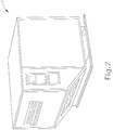
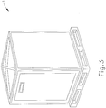
- the cargo container may take any form that is useful for transport aboard an airplane including, but not limited to, an aircraft-configured container 1 as shown in Fig. 2 , or a cargo-configured container 1 as shown in Fig. 3 .
- an active shutdown system There are two types of automatic shutdown systems according to the present disclosure: an active shutdown system and a passive shutdown system. These systems may be utilized separately or in combination.
- the active shutdown system remains operational for the duration of a flight. In the event that a fire signature is detected, the system automatically shuts down the exhaust fans, or automatically restricts the air flow from the exhaust fans of a refrigerated container for the remainder of the flight, or until the emergency has ended.
- the passive shutdown system operates by automatically turning off the exhaust fans, or automatically restricting the air flow from the exhaust fans when air transit is sensed.
- the automatic shutdown may occur just prior to takeoff, during the loading of the refrigerated cargo container, or at an early stage in the flight.
- the exhaust fans may be automatically reactivated or the airflow automatically restored to normal, when the end of air transit is sensed, for example, just prior to or during the unloading of the refrigerated cargo container from the airplane.
- the systems according to the present disclosure may use one or multiple types of sensors in varying quantities and positions with respect to the refrigerated cargo container.
- the sensors may be mounted on and/or in the refrigerated cargo container in any useful way.
- sensors which detect fire signatures may be mounted on the cargo container so that they are in communication with the exterior of the container. These sensors monitor the ambient condition around the perimeter of the refrigerated cargo container during transit.
- sensors may be mounted in locations in communication with the interior of the cargo container such that they may monitor the ambient conditions inside of the container.
- the sensors may be in close proximity to the fans or airflow. Non-limiting examples of such locations include in vents or air ducts
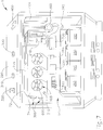
- Fig. 4 is a schematic of a vertical section through an exemplary refrigerated cargo container comprising an active shutdown system.
- a sensor 300 is externally placed on the top 290 of the container 1 such that it can sample the environment outside of the container.
- Further sensors 301, 302 are disposed on the inside of the refrigerated cargo container where they can sample for fire signatures within the container.
- One of the sensors, 301 is disposed near the condenser exhaust fans 103 which drive air from the inside of the container.
- Data captured by the sensors is outputted to a controller. If a fire signature is detected or if air transit is detected, the controller automatically shuts down the exhaust fans or automatically restricts the airflow output. Typically, this can be achieved by removing power to the fans, turning off the refrigeration system (for example by cutting power), turning off power to certain circuits which power the exhaust fans, or by closing or restricting the exhaust duct or vent airflow.
- the active flight mode system may comprise any useful sensor for detecting fire signatures.
- one or more of the sensors described below may be used in addition to, or in lieu of: a smoke detector; a particulate detector; a temperature sensor; a relative humidity sensor; and combinations thereof.
- the use of sensors is not intended to be limited to measuring fire signatures outside of the container. But rather, sensors may be present in communication with the inside of a refrigerated cargo container to monitor fires that could occur within the container's interior.
- the refrigerated cargo container's exhaust fans can operate safely until such time as a sensor detects a fire signature.
- a sensor detects a fire signature (e.g., infrared radiation, elevated temperature, etc.)
- the sensor may send a signal to the controller that automatically triggers the shutdown of the exhaust fan(s), or automatically restricts the air flow from the exhaust fan(s).
- the controller may be programmed to act only when two or more sensors detect a fire signature in unison.
- Non-limiting examples of useful sensors are selected from the group of: a thermal imagery sensor; a temperature sensor; a gas sensor; a light intensity sensor; a smoke and/or particulate detector; and combinations thereof.
- a thermal imagery sensor utilizes a thermographic camera to monitor for infrared emissions, such as hot spots and/or radiant energy that are indicative of a fire.
- Any suitable type of thermal imagery sensor may be used.
- Non-limiting examples of thermal imagery sensor types include: spark detectors; flame detectors; infrared (IR) black body heat emission detectors; and combinations thereof.
- the disclosed shutdown systems may comprise any one or more of these thermal imagery sensors.
- Useful thermal imagery sensors include the FLIR Compact A-Series thermal camera, which is available from FLIR Systems (Boston, MA).
- Flame detectors operate to monitor the area outside and/or inside of the refrigerated cargo container. Any suitable type of flame detector may be used.
- useful types of flame detectors include: ultraviolet detectors; near IR array detectors; infrared detectors; UV/IR detectors; IR/IR detectors; IR3 detectors; visible detectors; ionization current flame detectors; and thermocouple flame detectors.
- a non-limiting example of a useful ultraviolet flame detector is the HF-24 Ultraviolet Flame Detector, which is available from Hochiki America Corporation (Buena Park, CA).
- a temperature sensor utilizes a temperature probe to monitor the ambient temperature outside and/or inside of the refrigerated cargo container.
- temperature sensors include: fixed-temperature detectors; thermoelectric detectors; detectors that sense the rate in rise of temperature; and combinations thereof.
- Useful temperature sensors include the Thermistor Probe, which is available from U.S. Sensor Corp. (Orange, CA), the DFE 135/190 Fixed Temperature Heat Detector and the DCD-135-190 Fixed Temperature/Rate of Rise Detector, each of which is available from Hochiki America Corporation (Buena Park, CA).
- a gas sensor utilizes a meter to monitor the ambient concentrations of gas that is present outside and/or inside of the refrigerated cargo container.
- a gas sensor may be selected from the group of: oxygen sensors; carbon monoxide sensors; and combinations thereof.
- Useful oxygen sensors include XYA oxygen sensors which are available from Sensortechnics, Inc. (Mansfield, MA).
- a useful carbon monoxide detector is the Kidde KN-COB-IC Hardwire Carbon Monoxide Alarm, which is available from Kidde Fire Safety (Meban, NC).
- a light intensity sensor including but not limited to, an ultraviolet (UV) detector, may utilize a camera to monitor the ambient light outside and/or inside of the refrigerated cargo container. UV detectors are sensitive to most fires, including those involving hydrocarbons, metals, sulfur, hydrogen, hydrazine and ammonia. When light level that is indicative of a fire is detected, the light intensity sensor sends a signal to the controller which automatically triggers the shutdown of the exhaust fans, or automatically restricts the airflow output.
- Non-limiting examples of useful light intensity sensors include the following series of photo controls from Intermatic, Inc. (Spring Grove, IL): K1100, K1200, K4000C, K4100, K4400, K4200, K4500, LC4500 and LC2000.
- a smoke and/or particulate detector operates to monitor the area outside and/or inside of the refrigerated cargo container.
- smoke detectors include: ionization detectors; photoelectric detectors; and combinations thereof.
- Smoke detectors operating photoelectrically may provide a faster response to signals indicative of low energy fires (smoldering fires) as these first generally produce large quantities of visible (larger particle) smoke.
- Smoke detectors operating under the ionization principle typically provide a faster response to fires of high energy (open flames) as these fires provide for smaller smoke particles that are more easily detected by this type of detector.
- useful smoke and/or particulate detectors include the Direct-Wire Photoelectric Heat Smoke detector and the SLR-24H Photoelectric/Heat Smoke detector, each of which is available from Hochiki America Corporation (Buena Park, CA).
- Passive flight mode sensors monitor key conditions in relation to the container during air transit. When parameters are detected which indicate that the container is about to or has just entered air transit, the data from the device is outputted to a controller. The controller then automatically shuts down the exhaust fans, or automatically restricts the airflow output. Typically, this can be achieved by removing power to the fans, turning off the refrigeration unit or by closing, or otherwise restricting the exhaust duct or vent airflow.
- the controller may automatically turn the exhaust fans back on or increase the airflow output. Typically, this can be achieved by directing power to the exhaust fans, turning the refrigeration unit on, or by opening or by otherwise facilitating an increase in the airflow output.
- Passive flight mode sensor(s) are selected from the group of: accelerometers; altimeters; frequency/electric noise sensors; transponder signal receivers; global positioning systems (GPS); and combinations thereof.
- An accelerometer monitors the speed and acceleration forces that are associated with airplane takeoff. If takeoff is detected, the accelerometer sends a message to the controller which automatically shuts down the exhaust fans or automatically restricts the airflow output. In some embodiments, the accelerometer may be used to detect speed and deceleration forces that are associated with an airplane landing. If landing is detected, the accelerometer sends a message to the controller to automatically reactivate the exhaust fans or to return the airflow output to a desired level.
- useful accelerometers include the ACC793 Accelerometer, which is available from Omega Engineering, Inc. (Stamford, CT).
- An altimeter monitors the altitudes that are associated with airplane takeoff and landing. When takeoff is detected, the altimeter sends a message to the controller, which will then shut down the exhaust fans or restrict airflow output. When landing is detected, the altimeter may send a signal to the controller which will then automatically reactivate the exhaust fans when altitudes associated with an airplane landing are detected.
- useful altimeters include the NS5611-01BA03 Pressure Sensor which is available from Measurement Specialties (Hampton, VA).
- a frequency and/or electrical signal noise detector scans for the presence of electrical frequencies or electrical signal noise associated with airplane systems.
- the frequency and/or electrical signal noise detector may comprise detection circuits that monitor the electrical frequencies or noise via an antenna. When these signals are detected in close proximity, the controller may automatically shut down the exhaust fans or automatically restrict the exhaust airflow until the electrical frequencies or electrical signal noise is no longer detected. In some embodiments, if the detector no longer detects electrical frequencies or electrical signal noise, the exhaust fans may be automatically reactivated or the exhaust airflow automatically returned to normal output.
- a transponder signal receiver monitors for the presence of a transponder signal associated with an airplane or an air traffic control tower.
- detection circuits monitor an ADS-B transponder via an antenna for signals, broadcasts and/or transmissions that are either: assigned to the aircraft in which the cargo container is located, or is to be transported; and/or assigned to the airport facility.
- the exhaust fans will be automatically shut down or the exhaust restricted until the signal(s) are no longer detected. In some embodiments, the exhaust fans may then be automatically reactivated or the exhaust airflow automatically returned to normal output.
- a GPS may be used to track the location of the refrigerated cargo container relative to key locations including, but not limited to airports. Moreover, the GPS may be used to calculate the movement and/or speed profiles of a plane that is in motion. Based on the findings of the GPS, the controller will automatically shut down the exhaust fans or restrict the exhaust airflow until the transponder signal is no longer detected. In some embodiments, the exhaust fans will be automatically reactivated or the exhaust airflow will be automatically returned to normal when the GPS detects that the refrigerated cargo container has reached its destination.
- useful GPS include the GL200-Tracker with EMM Probe, which is available from 7PSolutions, LLC. (Brownsburg, IN).
- the controller receives signals from sensor(s) to determine if a fire signature is present inside or outside of the refrigerated cargo container and/or to determine whether air transit is taking place. Once the signal is received and understood, the protocols within the controller will automatically perform a shutdown of one or more functions of the refrigeration system to restrict airflow from the container.
- the controller may be present in the cargo container as an independent system 200, it may be incorporated into the container's power distribution/management system 201, or it may be incorporated into the container's active temperature control management system 202.
- the shutdown methodology may be as follows.
- the controller When the controller receives a signal indicating a parameter that may be related to fire or air transit, the controller will automatically perform functions that will stop or restrict the outgoing airflow from the container; this function can be performed in many ways and in many combinations.
- airflow is prevented from leaving the container by valves inside the ducting or vents that stop or redirect the airflow.
- airflow is turned off or the airflow rate is restricted by limiting the power supplied to the exhaust fan(s) thereby reducing the speed of the exhaust fan(s).
- the controller shuts down the refrigeration system.
- airflow direction is reversed to prevent the air from leaving the container by reversing the polarity of the power supplied to the fans.
- the shutdown system may comprise any useful configuration.
- Fig. 5 shows a block diagram of a combined active and passive shutdown system.
- Active shutdown sensors including a smoke detector 300, an oxygen sensor 310, and light intensity sensor 320, a temperature sensor 330, and a carbon monoxide detector 340, each of which are connected to the controller 104.
- passive shutdown sensors including a GPS 400 and a transponder signal receiver 410 are also connected to the controller 104.
- the controller 104 in turn is connected to the container power supplies, i.e., batteries 250 and an AC power supply 260.
- the controller 104 is also connected to the refrigeration compressor 240. If a fire signature and/or air transit is detected, then the controller 104 may automatically shut down the exhaust fans 103.
- the controller 104 may automatically cut the power to the refrigeration compressor 240.
- this example comprises an active and a passive shutdown system, its user has the flexibility of determining which system is the most appropriate to use for that particular shipment of cargo. Appropriateness may be determined by factors including how long the refrigerated cargo container can maintain a desired temperature without power to the refrigeration compressor.
- Fig. 6 is a rear, outside perspective view of an example of a refrigerated cargo container 1 comprising the combined active and passive shutdown system depicted in Fig. 5 .
- Vent slots 500 in a removable rear panel 275 correspond to where the condenser exhaust fans (not shown) are located interior to the removable panel 275.
- Fig. 7 is a rear, outside perspective view of the example of Fig. 6 , with the removable rear panel removed from the cargo container 1.
- An elongated fiber reinforced box-like support 74 is attached or bonded to the rear wall 72 of the outer shell 54 of the container and is enclosed by a second removable rear panel 276.
- a set of three refrigeration condenser exhaust fans 103 is supported by the box-like support 74.
- a restrictor valve 600 is located on each of the exhaust fans 103.
- a battery charger 264 is mounted on the rear wall 72 and is connected to a universal AC voltage supply 255.
- a motor driven refrigeration compressor 240 is mounted on the upper wall of the rectangular projection 74 and is connected to the internal and external DC power source through a compressor controller 800 that is located in the interior of the cargo container.
- a power distributer 700 is located in the interior of the cargo container.
- Another box-like support 280 is also attached or bonded to the rear wall 72 of the outer shell 54 and is also constructed from fiber reinforced composite panels, as disclosed in U.S. Pat. No. 6,740,381 .
- the support 280 has an open top and is opened at the rear for receiving and supporting the storage batteries 250.
- the support 74 and the rear wall 72 of the outer shell 54 also support the smoke detectors 300 and the oxygen sensor 310. Portions of the following sensors may be seen extending from or mounted flush with the roof 290 of the cargo container: a light intensity detector 320, a fixed temperature/rate in rise temperature sensor 330, a carbon monoxide detector 340 and a GPS 400. A transponder signal receiver is included in this example (not shown). In the event that any of the sensors detect a fire signature or air transit, the controller shuts down the exhaust fans.
- the present disclosure is directed to a method of automatically controlling the operation of the exhaust fan of a refrigerated cargo container.
- the method may utilize a passive shutdown system, an active shutdown system or combinations thereof.
- the method may be as follows.
- a sensor detects air transit of the refrigerated cargo container.
- Air transit is indicated by one or more flight phases. Flight phases may include: bringing the refrigerated cargo container to the airport; loading the refrigerated cargo container onto an airplane; airplane takeoff; airplane landing; offloading of the refrigerated cargo container from the airplane; and/or removing the refrigerated cargo container from the airport.
- Useful sensors may be selected from the group of: accelerometers; altimeters; frequency sensors; electric signal noise sensors; transponder signal receivers; global positioning systems; and combinations thereof.
- the controller will automatically perform functions that will stop or restrict the outgoing airflow from the container; this function can be performed in many ways and in many combinations,
- airflow is prevented from leaving the container by valves, such as butterfly valves, inside the ducting or vents that stop or redirect the airflow.
- airflow is turned off or the airflow rate is restricted by limiting the power supplied to the exhaust fan(s) thereby reducing the speed of the exhaust fan(s).
- the controller shuts down the refrigeration system.
- airflow direction is reversed to prevent the air from leaving the container by reversing the polarity of the power supplied to the fans.
- the method further comprises the step of the sensor detecting airplane landing or offloading of the refrigerated cargo container.
- the sensor communicates detection of either of these air transit phases to the controller.
- the controller will automatically perform functions that will replace, increase or redirect the outgoing airflow from the container; this function can be performed in many ways and in many combinations.
- the airflow may be allowed to leave the container by opening valves inside the ducting or vents that allow or redirect the airflow.
- airflow is turned on or the airflow rate is increased by increasing the power supplied to the exhaust fan(s) thereby increasing the speed of the exhaust fan(s).
- the controller turns the refrigeration system on.
- airflow direction is reversed to allow the air to leave the container by reversing the polarity of the power supplied to the fans.
- the method may be as follows.
- a sensor detects a fire signature.
- Fire signatures may include, but are not limited to: smoke; change in temperature; change in light; particulate matter; change in energy; and combinations thereof.
- Non-limiting examples of useful sensors may be selected from the group of: a thermal imagery sensor; a temperature sensor; a gas sensor; a light intensity sensor; a smoke and/or particulate detector; and combinations thereof. In some examples of the disclosure, one or more of these sensors may be used in addition to, or in lieu of: a smoke detector; a particulate detector; a temperature sensor; a relative humidity sensor; and combinations thereof.
- the controller will automatically perform functions that will stop or restrict the outgoing airflow from the container; this function can be performed in many ways and in many combinations.
- airflow is prevented from leaving the container by valves, such as butterfly valves, inside the ducting or vents that stop or redirect the airflow.
- airflow is turned off or the airflow rate is restricted by limiting the power supplied to the exhaust fan(s) thereby reducing the speed of the exhaust fan(s).
- the controller shuts down the refrigeration system.
- airflow direction is reversed to prevent the air from leaving the container by reversing the polarity of the power supplied to the fans.
- the method may be as follows. Sensors of use in the method may include those that are utilized to detect fire signatures and air transit as discussed in detail above. One or more sensors detect a fire signature prior to or after air transit, i.e., when the exhaust fans and/or the refrigeration system are operating normally. Air transit is indicated by one or more flight phases. Flight phases may include: bringing the refrigerated cargo container to the airport; loading the refrigerated cargo container onto an airplane; airplane takeoff; airplane landing; offloading of the refrigerated cargo container from the airplane; and/or removing the refrigerated cargo container from the airport.
- the controller is configured to automatically control the operation of the at least one exhaust fan in response to a fire signature and/or air transit.
- the controller will automatically perform functions that will stop or restrict the outgoing airflow from the container; this function can be performed in many ways and in many combinations.
- airflow is prevented from leaving the container by valves, such as butterfly valves, inside the ducting or vents that stop or redirect the airflow.
- airflow is turned off or the airflow rate is restricted by limiting the power supplied to the exhaust fan(s) thereby reducing the speed of the exhaust fan(s).
- the controller shuts down the refrigeration system.
- airflow direction is reversed to prevent the air from leaving the container by reversing the polarity of the power supplied to the fans.
Landscapes
- Engineering & Computer Science (AREA)
- Physics & Mathematics (AREA)
- Mechanical Engineering (AREA)
- Thermal Sciences (AREA)
- General Engineering & Computer Science (AREA)
- Chemical & Material Sciences (AREA)
- Combustion & Propulsion (AREA)
- Devices That Are Associated With Refrigeration Equipment (AREA)
- Fire-Detection Mechanisms (AREA)
- Emergency Alarm Devices (AREA)
- Alarm Systems (AREA)
Claims (12)
- Automatisches Herunterfahrsystem für einen gekühlten Frachtbehälter (1), wobei das System Folgendes umfasst:(a) einen Frachtbehälter (1), umfassend ein Kühlsystem (100), wobei das Kühlsystem zumindest ein Auslassgebläse (103) umfasst; und(b) zumindest einen Sensor, der kommunikativ an einer Steuerung (104) befestigt ist, wobei die Steuerung (104) kommunikativ an dem Kühlsystem (100) befestigt ist; dadurch gekennzeichnet, dass der zumindest eine Sensor ausgewählt wird aus der Gruppe aus: einem Beschleunigungsmesser; einem Höhenmesser; einem Frequenzsensor; einem elektrischen Signalrauschsensor; einem Transpondersignalempfänger (410); einem globalen Positionsbestimmungssystem (400); und Kombinationen daraus; und wobei die Steuerung dazu angeordnet ist, einen Luftstrom aus dem Auslassgebläse des Kühlsystems automatisch zu stoppen oder einzuschränken, wenn durch den zumindest einen Sensor ein Luftdurchgang detektiert wird, wobei Luftdurchgang alle Phasen von Transport an Bord eines Flugzeugs umfasst, einschließlich: Laden in das Flugzeug, Start, Flug, Landung und Ausladen aus dem Flugzeug.
- Automatisches Herunterfahrsystem nach Anspruch 1, ferner umfassend Sensoren, die ausgewählt werden aus der Gruppe aus: einem Temperatursensor (330); einem Sensor für relative Feuchtigkeit; einem Rauchsensor (300); einem Partikelsensor; einem Wärmebildsensor; einem Gassensor (310, 340); einem Lichtintensitätssensor (320); und Kombinationen daraus.
- Automatisches Herunterfahrsystem nach einem der Ansprüche 1 oder 2, wobei die Steuerung dazu ausgelegt ist, den Betrieb des Kühlsystems automatisch zu steuern in Reaktion auf die Detektion einer Feuersignatur durch zumindest einen Feuersignatursensor, wobei der zumindest eine Feuersignatursensor ausgewählt wird aus der Gruppe aus: einem Wärmebildsensor; einem Gassensor (310, 340); einem Lichtintensitätssensor (320); und Kombinationen daraus; und wobei die Feuersignatur vorzugsweise ausgewählt wird aus der Gruppe aus: Rauch; Partikeln; Infrarotemissionen; heißen Flecken; Strahlungsenergie, Temperatur; Sauerstoffkonzentration; Kohlenmonoxidkonzentration; ultraviolettem Licht; und Kombinationen daraus.
- Automatisches Herunterfahrsystem nach Anspruch 1, wobei die Steuerung dazu ausgelegt ist, den Betrieb des Kühlsystems in Reaktion auf Luftdurchgang automatisch zu steuern.
- Automatisches Herunterfahrsystem nach einem der vorhergehenden Ansprüche, wobei die Steuerung dazu ausgelegt ist, den Betrieb des zumindest einen Auslassgebläses automatisch zu steuern, wobei vorzugsweise die Steuerung dazu ausgelegt ist, den Luftstrom von dem zumindest einen Auslassgebläse automatisch zu stoppen oder automatisch einzuschränken.
- Automatisches Herunterfahrsystem nach Anspruch 1, wobei die Steuerung dazu ausgelegt ist, den Betrieb des zumindest einen Auslassgebläses in Reaktion auf eine Feuersignatur und einen Luftdurchgang automatisch zu steuern.
- Automatisches Herunterfahrsystem nach einem der vorhergehenden Ansprüche, wobei der Sensor an der Außenseite des gekühlten Frachtbehälters befindlich ist.
- Automatisches Herunterfahrsystem nach einem der vorhergehenden Ansprüche, wobei der Sensor im Inneren des gekühlten Frachtbehälters befindlich ist.
- Verfahren zum Steuern des Betriebs des Kühlsystems (100) eines gekühlten Frachtbehälters (1), wobei das Kühlsystem ein Auslassgebläse (103) umfasst, wobei das Verfahren die folgenden Schritte umfasst:(a) Detektieren von Luftdurchgang, wobei Luftdurchgang alle Phasen von Transport an Bord eines Flugzeugs umfasst, einschließlich: Laden in das Flugzeug, Start, Flug, Landung und Ausladen aus dem Flugzeug;(b) Kommunizieren von Detektion von Luftdurchgang an eine Steuerung (104); und(c) wobei die Steuerung (104) einen Luftstrom vom Auslassgebläse stoppt oder einschränkt, wenn Luftdurchgang durch zumindest einen Sensor detektiert wird, der ausgewählt ist aus der Gruppe aus: Beschleunigungsmessern; Höhenmessern; Frequenzsensoren; elektrischen Signalrauschsensoren; Transpondersignalempfängern (410); globalen Positionsbestimmungssystemen (400); und Kombinationen daraus.
- Verfahren nach Anspruch 9, ferner umfassend den Schritt des automatischen Ausschaltens des Auslassgebläses.
- Verfahren nach Anspruch 9, ferner umfassend den Schritt des automatischen Ausschaltens des Kühlsystems.
- Verfahren nach einem der Ansprüche 9 bis 11, ferner umfassend die Schritte des Detektierens einer Landung eines Flugzeugs; des Kommunizierens der Detektion einer Luftlandephase an die Steuerung; und des automatischen Wiederherstellens, Erhöhens oder Umleitens von Luftstrom vom Auslassgebläse.
Applications Claiming Priority (2)
| Application Number | Priority Date | Filing Date | Title |
|---|---|---|---|
| US201261653702P | 2012-05-31 | 2012-05-31 | |
| PCT/US2013/043673 WO2013181574A1 (en) | 2012-05-31 | 2013-05-31 | Automatic shutdown systems for refrigerated cargo containers |
Publications (2)
| Publication Number | Publication Date |
|---|---|
| EP2856046A1 EP2856046A1 (de) | 2015-04-08 |
| EP2856046B1 true EP2856046B1 (de) | 2020-11-11 |
Family
ID=48803593
Family Applications (1)
| Application Number | Title | Priority Date | Filing Date |
|---|---|---|---|
| EP13739303.9A Active EP2856046B1 (de) | 2012-05-31 | 2013-05-31 | Automatische herunterfahrsysteme für kühlfahrzeuge |
Country Status (4)
| Country | Link |
|---|---|
| US (1) | US10088226B2 (de) |
| EP (1) | EP2856046B1 (de) |
| JP (1) | JP6333810B2 (de) |
| WO (1) | WO2013181574A1 (de) |
Cited By (1)
| Publication number | Priority date | Publication date | Assignee | Title |
|---|---|---|---|---|
| EP4141357A1 (de) * | 2021-08-25 | 2023-03-01 | Thermo King Corporation | Transportkühleinheit und steuerungsverfahren |
Families Citing this family (12)
| Publication number | Priority date | Publication date | Assignee | Title |
|---|---|---|---|---|
| US10539353B2 (en) * | 2013-03-15 | 2020-01-21 | Daikin Applied Americas Inc. | Refrigerating apparatus and control device for refrigerating machine |
| JP6396662B2 (ja) * | 2013-03-15 | 2018-09-26 | ダイキン アプライド アメリカズ インコーポレィティッド | 冷凍装置および冷凍機の制御装置 |
| US10011418B2 (en) | 2014-09-26 | 2018-07-03 | Pelican Biothermal Llc | High efficiency bolt-on thermal insulating panel and thermally insulated shipping container employing such a thermal insulating panel |
| US10908062B2 (en) * | 2015-03-06 | 2021-02-02 | Scanit Technologies, Inc. | Airborne particle monitor |
| US10619907B2 (en) * | 2017-05-31 | 2020-04-14 | Keith A. Kenneally | Refrigerated, thermally insulated, collapsible cover system, assembly and method of using to transport perishable products |
| US11750008B2 (en) * | 2017-08-02 | 2023-09-05 | Doubleday Acquisitions Llc | Active container with data bridging |
| CN108710335A (zh) * | 2018-05-28 | 2018-10-26 | 宜昌市银岭冷冻设备有限公司 | 一种冷藏链的远程智能控制系统 |
| DE102019102211A1 (de) * | 2019-01-29 | 2020-07-30 | Miele & Cie. Kg | Verfahren und Steuergerät zum Erkennen einer Positionsänderung für ein Haushaltgerät und Haushaltgerät |
| US12157628B1 (en) | 2021-03-25 | 2024-12-03 | Energy Storage Response Group LLC | Systems and methods for purging smoke or other gasses from containers |
| CN115350420B (zh) * | 2022-07-01 | 2024-01-12 | 青岛鸿鹄航空科技有限公司 | 用于航空集装箱控制的方法及装置、航空集装箱 |
| US12292229B2 (en) * | 2023-01-24 | 2025-05-06 | Epazz, Inc | Foldable refrigerator |
| US20250100794A1 (en) * | 2023-09-25 | 2025-03-27 | Gentex Corporation | Unit load device monitoring system |
Citations (4)
| Publication number | Priority date | Publication date | Assignee | Title |
|---|---|---|---|---|
| US5058390A (en) * | 1990-05-25 | 1991-10-22 | Sundstrand Corporation | Aircraft vapor cycle cooling system with two speed control of a condenser fan and method of operation |
| EP0457431A2 (de) * | 1990-04-11 | 1991-11-21 | Transfresh Corporation | Atmosphäre-Überwachungs- und Steuersystem und Verfahren in Behältern für verderbliche atmende Güter |
| US20040226309A1 (en) * | 2003-02-17 | 2004-11-18 | Broussard Kenneth W. | Temperature controlled, pallet-sized shipping container |
| US20070289976A1 (en) * | 2005-06-08 | 2007-12-20 | Doubleday Acquisitions, Llc | Cargo container for transporting temperature sensitive items |
Family Cites Families (20)
| Publication number | Priority date | Publication date | Assignee | Title |
|---|---|---|---|---|
| US2449800A (en) * | 1944-12-08 | 1948-09-21 | Gen Electric | Refrigeration control apparatus |
| US2499736A (en) * | 1946-09-06 | 1950-03-07 | Kleen Nils Erland Af | Aircraft refrigeration |
| US2694537A (en) * | 1950-04-03 | 1954-11-16 | James B Reichert | Air-conditioned aircraft |
| US4399665A (en) * | 1981-12-07 | 1983-08-23 | Evans Hugh G | Aircraft air conditioning system |
| JPH0821678A (ja) | 1994-07-06 | 1996-01-23 | Temuko Kk | 冷・温蔵庫 |
| JP3162601B2 (ja) | 1995-05-19 | 2001-05-08 | 綜合警備保障株式会社 | 赤外線受光方式による火災検知方法 |
| JPH11351721A (ja) | 1998-06-09 | 1999-12-24 | Toyo Thermocontrol Kk | 地点指示装置を利用した冷凍機エンジン制御装置 |
| AUPQ174299A0 (en) * | 1999-07-21 | 1999-08-12 | Hill, Christopher Robin | Refrigerated air freight container |
| DE19950532A1 (de) * | 1999-10-20 | 2001-07-12 | Schoeller Plast Ag | Wiederverwendbares Beförderungsmittel mit Transponder |
| ES2573671T3 (es) | 1999-12-28 | 2016-06-09 | Milliken & Company | Núcleos de material compuesto reforzados con fibras |
| US6281797B1 (en) * | 2000-04-04 | 2001-08-28 | Marconi Data Systems Inc. | Method and apparatus for detecting a container proximate to a transportation vessel hold |
| US20040113783A1 (en) | 2002-12-11 | 2004-06-17 | Millennium Information Systems, Llc | Container integrity management system |
| WO2004063766A1 (en) | 2003-01-08 | 2004-07-29 | Envirotainer Ab | Activation of tracking device |
| EP1584077A1 (de) | 2003-01-14 | 2005-10-12 | United Technologies Corporation | Versandbehälter und verfahren zu seiner benutzung |
| JP2005140409A (ja) | 2003-11-06 | 2005-06-02 | Matsushita Electric Ind Co Ltd | 冷蔵庫 |
| US7263855B2 (en) | 2005-06-08 | 2007-09-04 | Doubleday Acquisitions, Llc | Cargo container for transporting temperature sensitive items |
| US20080020724A1 (en) | 2006-07-19 | 2008-01-24 | John Robert Orrell | Establishing a data link between stacked cargo containers |
| JP2008292341A (ja) | 2007-05-25 | 2008-12-04 | Toshiba Lighting & Technology Corp | 赤外線センサ装置 |
| US8162542B2 (en) * | 2008-02-25 | 2012-04-24 | Tednologies, Inc. | Environment controlled cargo container |
| US8248253B2 (en) | 2008-04-21 | 2012-08-21 | Honeywell International Inc. | Fire detector incorporating a gas sensor |
-
2013
- 2013-05-31 JP JP2015515253A patent/JP6333810B2/ja active Active
- 2013-05-31 US US13/907,169 patent/US10088226B2/en active Active
- 2013-05-31 EP EP13739303.9A patent/EP2856046B1/de active Active
- 2013-05-31 WO PCT/US2013/043673 patent/WO2013181574A1/en not_active Ceased
Patent Citations (4)
| Publication number | Priority date | Publication date | Assignee | Title |
|---|---|---|---|---|
| EP0457431A2 (de) * | 1990-04-11 | 1991-11-21 | Transfresh Corporation | Atmosphäre-Überwachungs- und Steuersystem und Verfahren in Behältern für verderbliche atmende Güter |
| US5058390A (en) * | 1990-05-25 | 1991-10-22 | Sundstrand Corporation | Aircraft vapor cycle cooling system with two speed control of a condenser fan and method of operation |
| US20040226309A1 (en) * | 2003-02-17 | 2004-11-18 | Broussard Kenneth W. | Temperature controlled, pallet-sized shipping container |
| US20070289976A1 (en) * | 2005-06-08 | 2007-12-20 | Doubleday Acquisitions, Llc | Cargo container for transporting temperature sensitive items |
Cited By (2)
| Publication number | Priority date | Publication date | Assignee | Title |
|---|---|---|---|---|
| EP4141357A1 (de) * | 2021-08-25 | 2023-03-01 | Thermo King Corporation | Transportkühleinheit und steuerungsverfahren |
| EP4235062A3 (de) * | 2021-08-25 | 2023-11-15 | Thermo King LLC | Transportkühleinheit und steuerungsverfahren |
Also Published As
| Publication number | Publication date |
|---|---|
| WO2013181574A1 (en) | 2013-12-05 |
| US10088226B2 (en) | 2018-10-02 |
| EP2856046A1 (de) | 2015-04-08 |
| JP2015526680A (ja) | 2015-09-10 |
| US20130319020A1 (en) | 2013-12-05 |
| JP6333810B2 (ja) | 2018-05-30 |
Similar Documents
| Publication | Publication Date | Title |
|---|---|---|
| EP2856046B1 (de) | Automatische herunterfahrsysteme für kühlfahrzeuge | |
| EP1437701B1 (de) | System, Steuerung und Verfahren zur Detektion eines gefährlichen Zustandes innerhalb eines mit einem Ventilationssystem ausgestatteten Raumes | |
| US10974085B2 (en) | Fire extinguishing container | |
| US11761703B2 (en) | Parallel loop intermodal container | |
| CN113758889B (zh) | 用于气体检测器的封壳 | |
| US20180327179A1 (en) | Refrigerated Transport System with Refrigerant Dilution | |
| CN113015641B (zh) | 经加热气体检测器 | |
| CN101937251A (zh) | 危险品运输车环境控制装置 | |
| JP2016104617A (ja) | 選択性の煙検知感度を実現するための方法及びシステム | |
| MX2012011084A (es) | Sistema de refrigeracion de aire licuado para un contenedor de almacenamiento. | |
| US20220172590A1 (en) | Fire detection in an occupied compartment | |
| EP3394528B1 (de) | Sicherheitssystem für einen behälter mit einem kühlsystem und verfahren um sicherheit zu gewährleisten | |
| US20230277884A1 (en) | Systems and methods for early controlled sprinkler activation | |
| US20250333180A1 (en) | Method and system for providing cooling to the hold of an aircraft | |
| US20240165680A1 (en) | Methods and systems for cleaning an electrically powered portable self-contained climate controlled storage unit | |
| CN121038863A (zh) | 储能系统爆燃和热传播缓解 |
Legal Events
| Date | Code | Title | Description |
|---|---|---|---|
| PUAI | Public reference made under article 153(3) epc to a published international application that has entered the european phase |
Free format text: ORIGINAL CODE: 0009012 |
|
| 17P | Request for examination filed |
Effective date: 20141211 |
|
| AK | Designated contracting states |
Kind code of ref document: A1 Designated state(s): AL AT BE BG CH CY CZ DE DK EE ES FI FR GB GR HR HU IE IS IT LI LT LU LV MC MK MT NL NO PL PT RO RS SE SI SK SM TR |
|
| AX | Request for extension of the european patent |
Extension state: BA ME |
|
| DAX | Request for extension of the european patent (deleted) | ||
| STAA | Information on the status of an ep patent application or granted ep patent |
Free format text: STATUS: EXAMINATION IS IN PROGRESS |
|
| 17Q | First examination report despatched |
Effective date: 20170905 |
|
| GRAP | Despatch of communication of intention to grant a patent |
Free format text: ORIGINAL CODE: EPIDOSNIGR1 |
|
| STAA | Information on the status of an ep patent application or granted ep patent |
Free format text: STATUS: GRANT OF PATENT IS INTENDED |
|
| INTG | Intention to grant announced |
Effective date: 20190913 |
|
| GRAJ | Information related to disapproval of communication of intention to grant by the applicant or resumption of examination proceedings by the epo deleted |
Free format text: ORIGINAL CODE: EPIDOSDIGR1 |
|
| STAA | Information on the status of an ep patent application or granted ep patent |
Free format text: STATUS: EXAMINATION IS IN PROGRESS |
|
| GRAP | Despatch of communication of intention to grant a patent |
Free format text: ORIGINAL CODE: EPIDOSNIGR1 |
|
| STAA | Information on the status of an ep patent application or granted ep patent |
Free format text: STATUS: GRANT OF PATENT IS INTENDED |
|
| INTC | Intention to grant announced (deleted) | ||
| INTG | Intention to grant announced |
Effective date: 20200217 |
|
| GRAJ | Information related to disapproval of communication of intention to grant by the applicant or resumption of examination proceedings by the epo deleted |
Free format text: ORIGINAL CODE: EPIDOSDIGR1 |
|
| STAA | Information on the status of an ep patent application or granted ep patent |
Free format text: STATUS: EXAMINATION IS IN PROGRESS |
|
| INTC | Intention to grant announced (deleted) | ||
| GRAR | Information related to intention to grant a patent recorded |
Free format text: ORIGINAL CODE: EPIDOSNIGR71 |
|
| GRAS | Grant fee paid |
Free format text: ORIGINAL CODE: EPIDOSNIGR3 |
|
| STAA | Information on the status of an ep patent application or granted ep patent |
Free format text: STATUS: GRANT OF PATENT IS INTENDED |
|
| GRAA | (expected) grant |
Free format text: ORIGINAL CODE: 0009210 |
|
| STAA | Information on the status of an ep patent application or granted ep patent |
Free format text: STATUS: THE PATENT HAS BEEN GRANTED |
|
| INTG | Intention to grant announced |
Effective date: 20200907 |
|
| AK | Designated contracting states |
Kind code of ref document: B1 Designated state(s): AL AT BE BG CH CY CZ DE DK EE ES FI FR GB GR HR HU IE IS IT LI LT LU LV MC MK MT NL NO PL PT RO RS SE SI SK SM TR |
|
| REG | Reference to a national code |
Ref country code: GB Ref legal event code: FG4D |
|
| REG | Reference to a national code |
Ref country code: CH Ref legal event code: EP |
|
| REG | Reference to a national code |
Ref country code: AT Ref legal event code: REF Ref document number: 1333871 Country of ref document: AT Kind code of ref document: T Effective date: 20201115 |
|
| REG | Reference to a national code |
Ref country code: DE Ref legal event code: R096 Ref document number: 602013073973 Country of ref document: DE |
|
| REG | Reference to a national code |
Ref country code: IE Ref legal event code: FG4D |
|
| REG | Reference to a national code |
Ref country code: SE Ref legal event code: TRGR |
|
| REG | Reference to a national code |
Ref country code: NL Ref legal event code: MP Effective date: 20201111 |
|
| REG | Reference to a national code |
Ref country code: AT Ref legal event code: MK05 Ref document number: 1333871 Country of ref document: AT Kind code of ref document: T Effective date: 20201111 |
|
| PG25 | Lapsed in a contracting state [announced via postgrant information from national office to epo] |
Ref country code: NO Free format text: LAPSE BECAUSE OF FAILURE TO SUBMIT A TRANSLATION OF THE DESCRIPTION OR TO PAY THE FEE WITHIN THE PRESCRIBED TIME-LIMIT Effective date: 20210211 Ref country code: PT Free format text: LAPSE BECAUSE OF FAILURE TO SUBMIT A TRANSLATION OF THE DESCRIPTION OR TO PAY THE FEE WITHIN THE PRESCRIBED TIME-LIMIT Effective date: 20210311 Ref country code: RS Free format text: LAPSE BECAUSE OF FAILURE TO SUBMIT A TRANSLATION OF THE DESCRIPTION OR TO PAY THE FEE WITHIN THE PRESCRIBED TIME-LIMIT Effective date: 20201111 Ref country code: FI Free format text: LAPSE BECAUSE OF FAILURE TO SUBMIT A TRANSLATION OF THE DESCRIPTION OR TO PAY THE FEE WITHIN THE PRESCRIBED TIME-LIMIT Effective date: 20201111 Ref country code: GR Free format text: LAPSE BECAUSE OF FAILURE TO SUBMIT A TRANSLATION OF THE DESCRIPTION OR TO PAY THE FEE WITHIN THE PRESCRIBED TIME-LIMIT Effective date: 20210212 |
|
| PG25 | Lapsed in a contracting state [announced via postgrant information from national office to epo] |
Ref country code: PL Free format text: LAPSE BECAUSE OF FAILURE TO SUBMIT A TRANSLATION OF THE DESCRIPTION OR TO PAY THE FEE WITHIN THE PRESCRIBED TIME-LIMIT Effective date: 20201111 Ref country code: IS Free format text: LAPSE BECAUSE OF FAILURE TO SUBMIT A TRANSLATION OF THE DESCRIPTION OR TO PAY THE FEE WITHIN THE PRESCRIBED TIME-LIMIT Effective date: 20210311 Ref country code: LV Free format text: LAPSE BECAUSE OF FAILURE TO SUBMIT A TRANSLATION OF THE DESCRIPTION OR TO PAY THE FEE WITHIN THE PRESCRIBED TIME-LIMIT Effective date: 20201111 Ref country code: BG Free format text: LAPSE BECAUSE OF FAILURE TO SUBMIT A TRANSLATION OF THE DESCRIPTION OR TO PAY THE FEE WITHIN THE PRESCRIBED TIME-LIMIT Effective date: 20210211 Ref country code: AT Free format text: LAPSE BECAUSE OF FAILURE TO SUBMIT A TRANSLATION OF THE DESCRIPTION OR TO PAY THE FEE WITHIN THE PRESCRIBED TIME-LIMIT Effective date: 20201111 |
|
| REG | Reference to a national code |
Ref country code: LT Ref legal event code: MG9D |
|
| PG25 | Lapsed in a contracting state [announced via postgrant information from national office to epo] |
Ref country code: HR Free format text: LAPSE BECAUSE OF FAILURE TO SUBMIT A TRANSLATION OF THE DESCRIPTION OR TO PAY THE FEE WITHIN THE PRESCRIBED TIME-LIMIT Effective date: 20201111 |
|
| PG25 | Lapsed in a contracting state [announced via postgrant information from national office to epo] |
Ref country code: SK Free format text: LAPSE BECAUSE OF FAILURE TO SUBMIT A TRANSLATION OF THE DESCRIPTION OR TO PAY THE FEE WITHIN THE PRESCRIBED TIME-LIMIT Effective date: 20201111 Ref country code: RO Free format text: LAPSE BECAUSE OF FAILURE TO SUBMIT A TRANSLATION OF THE DESCRIPTION OR TO PAY THE FEE WITHIN THE PRESCRIBED TIME-LIMIT Effective date: 20201111 Ref country code: LT Free format text: LAPSE BECAUSE OF FAILURE TO SUBMIT A TRANSLATION OF THE DESCRIPTION OR TO PAY THE FEE WITHIN THE PRESCRIBED TIME-LIMIT Effective date: 20201111 Ref country code: CZ Free format text: LAPSE BECAUSE OF FAILURE TO SUBMIT A TRANSLATION OF THE DESCRIPTION OR TO PAY THE FEE WITHIN THE PRESCRIBED TIME-LIMIT Effective date: 20201111 Ref country code: EE Free format text: LAPSE BECAUSE OF FAILURE TO SUBMIT A TRANSLATION OF THE DESCRIPTION OR TO PAY THE FEE WITHIN THE PRESCRIBED TIME-LIMIT Effective date: 20201111 Ref country code: SM Free format text: LAPSE BECAUSE OF FAILURE TO SUBMIT A TRANSLATION OF THE DESCRIPTION OR TO PAY THE FEE WITHIN THE PRESCRIBED TIME-LIMIT Effective date: 20201111 |
|
| REG | Reference to a national code |
Ref country code: DE Ref legal event code: R097 Ref document number: 602013073973 Country of ref document: DE |
|
| PG25 | Lapsed in a contracting state [announced via postgrant information from national office to epo] |
Ref country code: DK Free format text: LAPSE BECAUSE OF FAILURE TO SUBMIT A TRANSLATION OF THE DESCRIPTION OR TO PAY THE FEE WITHIN THE PRESCRIBED TIME-LIMIT Effective date: 20201111 |
|
| PLBE | No opposition filed within time limit |
Free format text: ORIGINAL CODE: 0009261 |
|
| STAA | Information on the status of an ep patent application or granted ep patent |
Free format text: STATUS: NO OPPOSITION FILED WITHIN TIME LIMIT |
|
| 26N | No opposition filed |
Effective date: 20210812 |
|
| PG25 | Lapsed in a contracting state [announced via postgrant information from national office to epo] |
Ref country code: NL Free format text: LAPSE BECAUSE OF FAILURE TO SUBMIT A TRANSLATION OF THE DESCRIPTION OR TO PAY THE FEE WITHIN THE PRESCRIBED TIME-LIMIT Effective date: 20201111 Ref country code: IT Free format text: LAPSE BECAUSE OF FAILURE TO SUBMIT A TRANSLATION OF THE DESCRIPTION OR TO PAY THE FEE WITHIN THE PRESCRIBED TIME-LIMIT Effective date: 20201111 Ref country code: AL Free format text: LAPSE BECAUSE OF FAILURE TO SUBMIT A TRANSLATION OF THE DESCRIPTION OR TO PAY THE FEE WITHIN THE PRESCRIBED TIME-LIMIT Effective date: 20201111 |
|
| PG25 | Lapsed in a contracting state [announced via postgrant information from national office to epo] |
Ref country code: SI Free format text: LAPSE BECAUSE OF FAILURE TO SUBMIT A TRANSLATION OF THE DESCRIPTION OR TO PAY THE FEE WITHIN THE PRESCRIBED TIME-LIMIT Effective date: 20201111 Ref country code: ES Free format text: LAPSE BECAUSE OF FAILURE TO SUBMIT A TRANSLATION OF THE DESCRIPTION OR TO PAY THE FEE WITHIN THE PRESCRIBED TIME-LIMIT Effective date: 20201111 |
|
| REG | Reference to a national code |
Ref country code: CH Ref legal event code: PL |
|
| PG25 | Lapsed in a contracting state [announced via postgrant information from national office to epo] |
Ref country code: CH Free format text: LAPSE BECAUSE OF NON-PAYMENT OF DUE FEES Effective date: 20210531 Ref country code: MC Free format text: LAPSE BECAUSE OF FAILURE TO SUBMIT A TRANSLATION OF THE DESCRIPTION OR TO PAY THE FEE WITHIN THE PRESCRIBED TIME-LIMIT Effective date: 20201111 Ref country code: LU Free format text: LAPSE BECAUSE OF NON-PAYMENT OF DUE FEES Effective date: 20210531 Ref country code: LI Free format text: LAPSE BECAUSE OF NON-PAYMENT OF DUE FEES Effective date: 20210531 |
|
| REG | Reference to a national code |
Ref country code: BE Ref legal event code: MM Effective date: 20210531 |
|
| PG25 | Lapsed in a contracting state [announced via postgrant information from national office to epo] |
Ref country code: IE Free format text: LAPSE BECAUSE OF NON-PAYMENT OF DUE FEES Effective date: 20210531 |
|
| PG25 | Lapsed in a contracting state [announced via postgrant information from national office to epo] |
Ref country code: IS Free format text: LAPSE BECAUSE OF FAILURE TO SUBMIT A TRANSLATION OF THE DESCRIPTION OR TO PAY THE FEE WITHIN THE PRESCRIBED TIME-LIMIT Effective date: 20210311 |
|
| PG25 | Lapsed in a contracting state [announced via postgrant information from national office to epo] |
Ref country code: BE Free format text: LAPSE BECAUSE OF NON-PAYMENT OF DUE FEES Effective date: 20210531 |
|
| PG25 | Lapsed in a contracting state [announced via postgrant information from national office to epo] |
Ref country code: HU Free format text: LAPSE BECAUSE OF FAILURE TO SUBMIT A TRANSLATION OF THE DESCRIPTION OR TO PAY THE FEE WITHIN THE PRESCRIBED TIME-LIMIT; INVALID AB INITIO Effective date: 20130531 |
|
| PG25 | Lapsed in a contracting state [announced via postgrant information from national office to epo] |
Ref country code: CY Free format text: LAPSE BECAUSE OF FAILURE TO SUBMIT A TRANSLATION OF THE DESCRIPTION OR TO PAY THE FEE WITHIN THE PRESCRIBED TIME-LIMIT Effective date: 20201111 |
|
| P01 | Opt-out of the competence of the unified patent court (upc) registered |
Effective date: 20230605 |
|
| PG25 | Lapsed in a contracting state [announced via postgrant information from national office to epo] |
Ref country code: MK Free format text: LAPSE BECAUSE OF FAILURE TO SUBMIT A TRANSLATION OF THE DESCRIPTION OR TO PAY THE FEE WITHIN THE PRESCRIBED TIME-LIMIT Effective date: 20201111 |
|
| PG25 | Lapsed in a contracting state [announced via postgrant information from national office to epo] |
Ref country code: TR Free format text: LAPSE BECAUSE OF FAILURE TO SUBMIT A TRANSLATION OF THE DESCRIPTION OR TO PAY THE FEE WITHIN THE PRESCRIBED TIME-LIMIT Effective date: 20201111 |
|
| PG25 | Lapsed in a contracting state [announced via postgrant information from national office to epo] |
Ref country code: MT Free format text: LAPSE BECAUSE OF FAILURE TO SUBMIT A TRANSLATION OF THE DESCRIPTION OR TO PAY THE FEE WITHIN THE PRESCRIBED TIME-LIMIT Effective date: 20201111 |
|
| PGFP | Annual fee paid to national office [announced via postgrant information from national office to epo] |
Ref country code: DE Payment date: 20250529 Year of fee payment: 13 |
|
| PGFP | Annual fee paid to national office [announced via postgrant information from national office to epo] |
Ref country code: GB Payment date: 20250527 Year of fee payment: 13 |
|
| PGFP | Annual fee paid to national office [announced via postgrant information from national office to epo] |
Ref country code: FR Payment date: 20250526 Year of fee payment: 13 |
|
| PGFP | Annual fee paid to national office [announced via postgrant information from national office to epo] |
Ref country code: SE Payment date: 20250527 Year of fee payment: 13 |