EP2856074B1 - Nicht tödliches geschoss - Google Patents
Nicht tödliches geschoss Download PDFInfo
- Publication number
- EP2856074B1 EP2856074B1 EP13728923.7A EP13728923A EP2856074B1 EP 2856074 B1 EP2856074 B1 EP 2856074B1 EP 13728923 A EP13728923 A EP 13728923A EP 2856074 B1 EP2856074 B1 EP 2856074B1
- Authority
- EP
- European Patent Office
- Prior art keywords
- projectile
- plug
- catching piece
- peg
- projectile according
- Prior art date
- Legal status (The legal status is an assumption and is not a legal conclusion. Google has not performed a legal analysis and makes no representation as to the accuracy of the status listed.)
- Active
Links
- 231100001160 nonlethal Toxicity 0.000 title claims description 5
- 239000000463 material Substances 0.000 claims description 6
- 239000004033 plastic Substances 0.000 claims description 6
- 238000010304 firing Methods 0.000 claims description 5
- 230000005484 gravity Effects 0.000 claims description 3
- 230000007704 transition Effects 0.000 claims description 3
- 230000000694 effects Effects 0.000 claims 1
- 230000000284 resting effect Effects 0.000 claims 1
- 230000006378 damage Effects 0.000 description 6
- 208000027418 Wounds and injury Diseases 0.000 description 5
- 208000014674 injury Diseases 0.000 description 5
- 238000010008 shearing Methods 0.000 description 3
- 230000008901 benefit Effects 0.000 description 2
- 239000006260 foam Substances 0.000 description 2
- 231100000518 lethal Toxicity 0.000 description 2
- 230000001665 lethal effect Effects 0.000 description 2
- 238000004519 manufacturing process Methods 0.000 description 2
- 239000007779 soft material Substances 0.000 description 2
- 229920001169 thermoplastic Polymers 0.000 description 2
- 239000004416 thermosoftening plastic Substances 0.000 description 2
- 208000020564 Eye injury Diseases 0.000 description 1
- 241000238367 Mya arenaria Species 0.000 description 1
- 230000009471 action Effects 0.000 description 1
- 230000008859 change Effects 0.000 description 1
- 239000007788 liquid Substances 0.000 description 1
- 239000002184 metal Substances 0.000 description 1
- 238000000465 moulding Methods 0.000 description 1
- 230000035515 penetration Effects 0.000 description 1
- 238000000926 separation method Methods 0.000 description 1
- 239000007787 solid Substances 0.000 description 1
- 230000006641 stabilisation Effects 0.000 description 1
- 238000011105 stabilization Methods 0.000 description 1
Images


Classifications
-
- F—MECHANICAL ENGINEERING; LIGHTING; HEATING; WEAPONS; BLASTING
- F42—AMMUNITION; BLASTING
- F42B—EXPLOSIVE CHARGES, e.g. FOR BLASTING, FIREWORKS, AMMUNITION
- F42B12/00—Projectiles, missiles or mines characterised by the warhead, the intended effect, or the material
- F42B12/02—Projectiles, missiles or mines characterised by the warhead, the intended effect, or the material characterised by the warhead or the intended effect
-
- F—MECHANICAL ENGINEERING; LIGHTING; HEATING; WEAPONS; BLASTING
- F41—WEAPONS
- F41A—FUNCTIONAL FEATURES OR DETAILS COMMON TO BOTH SMALLARMS AND ORDNANCE, e.g. CANNONS; MOUNTINGS FOR SMALLARMS OR ORDNANCE
- F41A21/00—Barrels; Gun tubes; Muzzle attachments; Barrel mounting means
- F41A21/26—Barrels; Gun tubes; Muzzle attachments; Barrel mounting means specially adapted for recoil reinforcement, e.g. for training purposes
-
- F—MECHANICAL ENGINEERING; LIGHTING; HEATING; WEAPONS; BLASTING
- F41—WEAPONS
- F41A—FUNCTIONAL FEATURES OR DETAILS COMMON TO BOTH SMALLARMS AND ORDNANCE, e.g. CANNONS; MOUNTINGS FOR SMALLARMS OR ORDNANCE
- F41A21/00—Barrels; Gun tubes; Muzzle attachments; Barrel mounting means
- F41A21/32—Muzzle attachments or glands
-
- F—MECHANICAL ENGINEERING; LIGHTING; HEATING; WEAPONS; BLASTING
- F41—WEAPONS
- F41C—SMALLARMS, e.g. PISTOLS, RIFLES; ACCESSORIES THEREFOR
- F41C27/00—Accessories; Details or attachments not otherwise provided for
- F41C27/06—Adaptations of smallarms for firing grenades, e.g. rifle grenades, or for firing riot-control ammunition; Barrel attachments therefor
-
- F—MECHANICAL ENGINEERING; LIGHTING; HEATING; WEAPONS; BLASTING
- F42—AMMUNITION; BLASTING
- F42B—EXPLOSIVE CHARGES, e.g. FOR BLASTING, FIREWORKS, AMMUNITION
- F42B12/00—Projectiles, missiles or mines characterised by the warhead, the intended effect, or the material
- F42B12/02—Projectiles, missiles or mines characterised by the warhead, the intended effect, or the material characterised by the warhead or the intended effect
- F42B12/36—Projectiles, missiles or mines characterised by the warhead, the intended effect, or the material characterised by the warhead or the intended effect for dispensing materials; for producing chemical or physical reaction; for signalling ; for transmitting information
-
- F—MECHANICAL ENGINEERING; LIGHTING; HEATING; WEAPONS; BLASTING
- F42—AMMUNITION; BLASTING
- F42B—EXPLOSIVE CHARGES, e.g. FOR BLASTING, FIREWORKS, AMMUNITION
- F42B12/00—Projectiles, missiles or mines characterised by the warhead, the intended effect, or the material
- F42B12/72—Projectiles, missiles or mines characterised by the warhead, the intended effect, or the material characterised by the material
- F42B12/74—Projectiles, missiles or mines characterised by the warhead, the intended effect, or the material characterised by the material of the core or solid body
- F42B12/745—Projectiles, missiles or mines characterised by the warhead, the intended effect, or the material characterised by the material of the core or solid body the core being made of plastics; Compounds or blends of plastics and other materials, e.g. fillers
-
- F—MECHANICAL ENGINEERING; LIGHTING; HEATING; WEAPONS; BLASTING
- F42—AMMUNITION; BLASTING
- F42B—EXPLOSIVE CHARGES, e.g. FOR BLASTING, FIREWORKS, AMMUNITION
- F42B30/00—Projectiles or missiles, not otherwise provided for, characterised by the ammunition class or type, e.g. by the launching apparatus or weapon used
- F42B30/04—Rifle grenades
- F42B30/06—Bullet traps or bullet decelerators therefor
-
- F—MECHANICAL ENGINEERING; LIGHTING; HEATING; WEAPONS; BLASTING
- F42—AMMUNITION; BLASTING
- F42B—EXPLOSIVE CHARGES, e.g. FOR BLASTING, FIREWORKS, AMMUNITION
- F42B8/00—Practice or training ammunition
- F42B8/12—Projectiles or missiles
Definitions
- the invention relates to a non-fatal projectile (referred to in the literature "non lethal bullet” or “less lethal bullet”) for firing by means of a firearm, which projectile on the barrel of a firearm - especially a handgun - attachable and shootable by firing a common projectile wherein the projectile has a body whose interior contains a catching device for the projectile.
- non lethal bullet or “less lethal bullet”
- Such bullets are used for example by executive forces against persons. They should not inflict serious injury on those affected, but prevent them from committing criminal acts. Because situations requiring the use of such bullets can occur unexpectedly, such bullets must be fireable by firing a common projectile. This should also allow it, after firing of such a projectile gun immediately to use again for a shot with a common projectile.
- Such a non-lethal bullet is in the WO 01/11305 proposed. It consists of a mounted on the barrel hollow cylinder with a front fragile impact head, which can be filled with a liquid.
- the hollow cylinder is closed at the front by a projectile trap which, according to the description, consists of a material which can not be penetrated by the projectile.
- the initial speed of the projectile is 10 percent slower than the running exit speed of the projectile is.
- the undetectable project infiltrates suggest: it transmits almost all of the projectile's kinetic energy to the projectile, and the projectile is far too fast to be harmless. Apart from the spindle-shaped figure and the wings, even the fragile impact head can not change that. This floor is thus unsuitable for the purpose mentioned.
- the invention achieves the above-mentioned object with the features of independent claim 1.
- the solution is that the safety gear consumes a considerable portion of the kinetic energy of the projectile by friction and a fraction of which translates into kinetic energy of the non-fatal projectile, and that a part of the projectile plugged into the mouth of the barrel and also part of the safety gear is. This ensures that a relatively light projectile can still be fired with sufficient speed for the required range without being deformed or even destroyed by the projectile.
- the attachment of the projectile in the mouth of the barrel has the advantage that the projectile can be fired by means of different weapons of the same caliber in comparison with fastened to the outside of the barrel fasteners.
- the safety gear for consumption or for converting a major part of the kinetic energy of the projectile from at least one in the body over a distance in the longitudinal direction by overcoming frictional forces and plastically deformable by deformation forces plug It is only through the combination of a sufficient friction path and the internal friction overcome by plastic deformation of the plug that a sufficient amount of kinetic energy of the projectile is consumed.
- the catching device consists of a plug and a catching piece, wherein the rear part of the plug is a plug which can be plugged into the mouth of the barrel, and the front part of the plug forms a cylinder cooperating with the catching piece.
- the plug performs two functions: First, it forms a co-operating with the catch friction surface, which may be sized and designed suitable for the purpose of energy destruction. Second, it is in the barrel and thus serves the attachment of the projectile in the mouth of the barrel.
- the front part of the plug is a hollow cylinder whose inner diameter is equal to or greater than the outer diameter of the pin.
- the hollow cylinder is located on an axis normal annular surface the catching piece and forms a predetermined breaking point because of its inner diameter at the transition to the rear pin of the plug. When shearing the hollow cylinder at the predetermined breaking point further kinetic energy of the projectile is consumed.
- the catching piece is a hollow cylinder, which has a centric, closed at its front and rear open blind hole.
- the catching piece is pressed into a likewise closed at the front and rear open blind bore of the projectile body over only a portion of its length, so that the catching piece over the remaining part of the length of the blind bore is force application displaced.
- the diameter of the blind hole is equal to or smaller than the diameter of the pin.
- the plug consists of a ductile material (preferably a thermoplastic) and has at its rear end a central recess from which, starting from the pin of the plug under the action of the impinging projectile is deformed.
- the deformation of the plug consumes additional kinetic energy.
- the projectile impinging on the central recess penetrates completely into the journal and deforms it into a tubular structure. Because of the large deformed volume of the pin, a lot of energy is consumed.
- the lengths of catching piece, plug, blind hole and blind hole are chosen so that the center of gravity of the projectile with the shifted and / or deformed parts and the projectile in its interior in free flight is approximately in the geometric center and that the rear edge of the catching piece does not protrude beyond the contour of the body of the projectile. In the case of the spherical outer contour of the projectile, this is the center of the sphere.
- the spherical outer contour solves a secondary problem: Since a transfer of the swirl of the projectile on the projectile, if at all, takes place only to a very small extent, a spin stabilization of the projectile is not given. For the use of wings (see WO 01/11305 ) the airspeed is not enough. A missile of elongated shape would therefore "whine" in the air and could strike as a ricochet. Thanks to the spherical outer contour of the projectile, and especially in the central position of the center of mass, the projectile can rotate in flight at will, so that it is uncertain with which point of its outer contour the projectile hits.
- the body of the projectile is surrounded by a soft shell of, for example, foam or other soft material, he does not need to be spherical (which reduces its weight) and the coat of soft material ensures that the target person no lethal injuries occur.
- the existing example of plastic body may have circumferentially extending ribs. This also facilitates the production of the jacket by molding.
- the production of the body made of plastic has the further advantage that it can give way upon expansion of the catching piece by penetration of the projectile.
- the diameter of the spherical contour is greater than 4, preferably 5 cm, the projectile does not fit into the orbit of a target person, which prevents serious eye injuries. If it is further ensured that the rear edge of the catching piece does not protrude beyond the contour of the body of the projectile, striking the rear zone of the projectile can not cause any serious injuries.
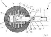
- Fig. 1 is the projectile according to the invention with 1 and any gun designated 2. Of the latter, only the front part of a carriage 3 and a barrel 4 can be seen, in which a projectile 5 is already underway. Fig. 1 thus represents the first movement phase.
- the projectile 1 consists first of a body 7 and a shell 8.
- the body 7 is made of a lightweight metal or a solid plastic (for example, a thermoplastic) and has circumferentially extending ribs 9. To form the shell 8, he is from a surrounded by soft foam.
- the body 7 has a longitudinal central blind bore 10 which forms a bottom 11 at its front end. As can be seen, the blind bore extends over most of the length of the body 7. At its rear, open, end, the blind bore 10 has an extension 13 which terminates at a first shoulder 12.
- the arranged inside the body catching device consists of a catching piece 15 and a plug 22.
- the catching piece 15 is a circular cylinder with a blind hole 17 which ends in front in a bottom 18.
- the outer diameter of the cylinder has an excess of the inner diameter of the blind bore 10, so that it is displaceable only by overcoming the considerable frictional resistance in the longitudinal direction.
- the catching piece 15 has an outwardly projecting collar 16 and a rearwardly projecting collar 20.
- the collar 20 has the same or a slightly larger inner diameter than the blind hole 17 and goes over a second shoulder 19 in this over.
- the plug 22 is a pin 23, which merges forward into a hollow cylinder 24.
- the transition 25 represents an all-round predetermined breaking point.
- the pin 23 is in the barrel and thus keeps the projectile 1 ready.
- the pin 23 has at its rear end a central recess 26 at which the projectile strikes with the consequences to be described below.
- the plug 22 is made of a ductile material which may be metallic or preferably a suitable tough and strong plastic.
- Fig. 1 If a shot has already been fired, the projectile 5 is in the barrel 4 and moves towards the stopper 22. It will immediately push the pin 23 out of the barrel and exert on the pin 23 a force that pushes him into the blind hole 17. Since the hollow cylinder 24 of the plug 22 is supported on the second shoulder 19 of the catching piece 15, pin 23 and the hollow cylinder 24 are separated from each other at the predetermined breaking point 25. Since the inner diameter of the hollow cylinder 24 is equal to or larger than the diameter of the Pin 23 is the separation is done by shearing. Already this kinetic energy of the projectile is consumed.
- the sliding path 21 is in Fig. 2
- the projectile begins 5, to penetrate into the central recess 26 of the pin 23. This is the main purpose of the central recess 26.
- Fig. 3 is the projectile 5 already penetrated completely into the pin 23, while it has this under considerable deformation work to a tubular structure 23 * reshaped.
- the wall of the catching piece 15 has also deformed outwards, which is possible without damaging it because of the material selection of the body 7.
- the center of gravity of the entire projectile with the safety gear and the projectile in the end position is approximately at the geometric center of the projectile Fig. 3 can also be seen that in the final position the catching piece 15 whose collar 20 remains within the contour of the body 7 and therefore can not cause any significant injury to the target person with the image in the rear zone when the projectile strikes the projectile.
Landscapes
- Engineering & Computer Science (AREA)
- General Engineering & Computer Science (AREA)
- Chemical & Material Sciences (AREA)
- Combustion & Propulsion (AREA)
- Physics & Mathematics (AREA)
- Thermal Sciences (AREA)
- Aiming, Guidance, Guns With A Light Source, Armor, Camouflage, And Targets (AREA)
Description
- Die Erfindung betrifft ein nicht tödliches Geschoß (in der Fachliteratur "non lethal bullet" oder "less lethal bullet" genannt) zum Verschießen mittels einer Feuerwaffe, welches Geschoß am Lauf einer Feuerwaffe - insbesondere einer Faustfeuerwaffe - anbringbar und durch Abfeuern eines gebräuchlichen Projektils verschießbar ist, wobei das Geschoß einen Körper aufweist, dessen Inneres eine Fangvorrichtung für das Projektil enthält. Derartige Geschoße werden beispielsweise von Exekutivkräften gegen Personen eingesetzt. Sie sollen den Betroffenen keine ernsthaften Verletzungen zufügen, sondern sie von kriminellen Handlungen abhalten. Weil Situationen, die den Einsatz solcher Geschoße erfordern, unerwartet auftreten können, müssen solche Geschoße durch Abfeuern eines gebräuchlichen Projektils verschießbar sein. Das soll es auch erlauben, nach Abfeuern eines solchen Geschoßes die Waffe sofort wieder für einen Schuss mit einem gebräuchlichen Projektil einzusetzen.
- Ein derartiges nicht tödliches Geschoß wird in der
WO 01/11305 - Bei mittels eines Projektils verschießbaren Gewehrgranaten ist es zum Erreichen einer ausreichenden Einsatzschutzweite notwendig, möglichst die gesamte kinetische Energie des Projektils auf das Geschoß zu übertragen, zumal die Masse einer Gewehrgranate ein vielfaches der Masse des Projektils beträgt. Aus der
GB 2223833 A - Aus der
US 7,526,999 ist ein außen am Verschlussschlitten ansetzbares Geschoß bekannt, auf das die Energie des Projektils vorwiegend durch dessen Verformung stattfindet. Reibung spielt dabei praktisch keine Rolle. - Bei einem für den eingangs erläuterten Zweck einsetzbaren Geschoß kommt es zunächst darauf an, dass dessen Beschaffenheit (Gestalt und Masse) keine Verletzungen hervorruft und vor allem darauf, dass seine Auftreffgeschwindigkeit auch bei geringer Entfernung des Zieles relativ gering ist. Das ist das der vorliegenden Erfindung zugrunde liegende Problem.
- Die Erfindung löst die oben genannte Aufgabe mit den Merkmalen des unabhängigen Anspruchs 1.
- Erfindungsgemäß besteht die Lösung darin, dass die Fangvorrichtung einen erheblichen Teil der kinetischen Energie des Projektils durch Reibung verbraucht und einen Bruchteil derer in kinetische Energie des nicht tödlichen Geschoßes umsetzt, und dass ein Teil des Geschoßes in die Mündung des Laufes einsteckbar und auch Teil der Fangvorrichtung ist. Dadurch wird erreicht, dass ein relativ leichtes Geschoß mit noch immer für die erforderliche Reichweite ausreichender Geschwindigkeit abgeschossen werden kann, ohne durch das Projektil deformiert oder gar zerstört zu werden. Die Befestigung des Geschoßes in der Mündung des Laufes hat im Vergleich mit außen am Lauf aufgesteckten Befestigungsmitteln den Vorteil, dass das Geschoß mittels verschiedener Waffen gleichen Kalibers verschossen werden kann.
- Dazu besteht die Fangvorrichtung zum Verbrauch beziehungsweise zur Umwandlung eines Großteils der kinetischen Energie des Projektils aus zumindest einem im Körper über eine Wegstrecke in Längsrichtung unter Überwindung von Reibungskräften verschiebbaren und von Verformungskräften plastisch verformbaren Stopfen. Erst durch die Kombination aus einem ausreichenden Reibungsweg und der bei plastischer Verformung des Stopfens überwundenen inneren Reibung wird eine ausreichende Menge an kinetischer Energie des Projektils verbraucht.
- In einer praktischen Ausgestaltung besteht die Fangvorrichtung aus einem Stopfen und einem Fangstück, wobei der hintere Teil des Stopfens ein in die Mündung des Laufes steckbarer Zapfen ist, und der vordere Teil des Stopfens einen mit dem Fangstück zusammenwirkenden Zylinder bildet. Der Stopfen erfüllt zwei Funktionen: Erstens bildet er eine mit dem Fangstück zusammenwirkende Reibfläche, die für den Zweck der Energievernichtung geeignet dimensioniert und ausgebildet sein kann. Zweitens steckt er im Lauf und dient so der Befestigung des Geschoßes in der Mündung des Laufes.
- In einer besonderen Ausbildung ist der vordere Teil des Stopfens ein Hohlzylinder, dessen innerer Durchmesser gleich oder größer als der Außendurchmesser des Zapfens ist. Der Hohlzylinder liegt an einer achsnormalen Kreisringfläche des Fangstückes an und bildet wegen seines inneren Durchmessers am Übergang zum hinteren Zapfen des Stopfens eine Sollbruchstelle. Bei Abscheren des Hohlzylinders an der Sollbruchstelle wird weitere kinetische Energie des Projektils verbraucht.
- In einer bevorzugten Weiterbildung der Erfindung ist das Fangstück ein Hohlzylinder, der ein zentrisches, an seiner Vorderseite geschlossenes und hinten offenes Sackloch aufweist. Das Fangstück ist in eine ebenfalls vorne geschlossene und hinten offene Sackbohrung des Geschoßkörpers über nur einen Teil deren Länge eingepresst, sodass das Fangstück über den restlichen Teil der Länge der Sackbohrung unter Kraftanwendung verschiebbar ist. In das Sackloch des Fangstückes ist der Zapfen nach dem Abscheren an der Sollbruchstelle unter Überwindung von Reibungskräften einschiebbar. Der Durchmesser des Sackloches ist dabei gleich oder kleiner als der Durchmesser des Zapfens. So werden zwei Reibungsflächen erheblicher Länge geschaffen: eine erste zwischen dem Zapfen und dem Fangstück und eine zweite zwischen dem Fangstück und dem Körper des Geschoßes. Dadurch wird die Reibungslänge (der "Bremsweg") verdoppelt, also insgesamt eine erhebliche Reibungsstrecke geschaffen, bei gegebener Länge des Geschoßes.
- In Weiterbildung der Erfindung besteht der Stopfen aus einem duktilen Werkstoff (vorzugsweise einem Thermoplast) und weist an seinem hintern Ende eine zentrische Ausnehmung auf, von der ausgehend der Zapfen des Stopfens unter der Einwirkung des auftreffenden Projektils verformbar ist. Durch die Verformung des Stopfens wird weitere kinetische Energie verbraucht. Das an der zentrischen Ausnehmung auftreffende Projektil dringt ganz in den Zapfen ein und verformt ihn zu einem rohrförmigen Gebilde. Wegen des großen verformten Volumens des Zapfens wird dabei besonders viel Energie verbraucht.
- In einer weitergebildeten Ausgestaltung der Erfindung sind die Längen von Fangstück, Stopfen, Sackloch und Sackbohrung so gewählt, dass der Schwerpunkt des Geschoßes mit den verschobenen und/oder verformten Teilen und dem Projektil in seinem Inneren im freien Flug ungefähr in dessen geometrischem Zentrum liegt und dass der hintere Rand des Fangstückes nicht über die Kontur des Körpers des Geschoßes hinausragt. Bei sphärischer Außenkontur des Geschoßes ist das der Mittelpunkt der Kugel.
- Die sphärische Außenkontur löst ein sekundäres Problem: Weil eine Übertragung des Dralles des Projektils auf das Geschoß, wenn überhaupt, nur in sehr geringem Ausmaß erfolgt, ist eine Drallstabilisierung des Geschoßes nicht gegeben. Für die Verwendung von Flügeln (siehe
WO 01/11305 - Zur Reduktion des Gewichtes und zur besseren Verbindung zwischen dem Körper des Geschoßes und dem außen sphärischen Mantel kann der beispielsweise aus Kunststoff bestehende Körper in Umfangsrichtung verlaufende Rippen aufweisen. Das erleichtert auch die Herstellung des Mantels durch Umspritzen. Die Herstellung des Körpers aus Kunststoff hat noch den weiteren Vorteil, dass er bei Aufweiten des Fangstückes durch Eindringen des Projektils nachgeben kann.
- Schließlich dienen im Rahmen der Erfindung noch zwei Maßnahmen der Sicherheit der Zielperson: Wenn der Durchmesser der sphärischen Kontur größer als 4, vorzugsweise 5 cm ist, passt das Geschoß nicht in die Augenhöhle einer Zielperson, was schweren Augenverletzungen vorbeugt. Wenn weiters sichergestellt ist, dass der hintere Rand des Fangstückes nicht über die Kontur des'Körpers des Geschoßes hinausragt, kann auch ein Auftreffen mit der hinteren Zone des Geschoßes keine schwereren Verletzungen verursachen.
- Im Folgenden wird die Erfindung anhand von Abbildungen beschrieben und erläutert. Es stellen dar:
- Fig.1:
- Einen Längsschnitt durch ein Ausführungsbeispiel eines erfindungsgemäße Geschoßes in einer ersten Phase,
- Fig. 2:
- Dasselbe, in einer zweiten Phase,
- Fig. 3:
- Dasselbe in einer dritten Phase.
- In
Fig. 1 ist das erfindungsgemäße Geschoß mit 1 und eine beliebige Pistole mit 2 bezeichnet. Von letzterer ist nur der vordere Teil eines Laufschlittens 3 und eines Laufes 4 zu sehen, in dem ein Projektil 5 bereits unterwegs ist.Fig. 1 stellt somit auch die erste Bewegungsphase dar. - Das erfindungsgemäße Geschoß 1 besteht zunächst aus einem Körper 7 und einer Hülle 8. Der Körper 7 ist aus einem leichten Metall oder einem festen Kunststoff (beispielsweise einem Thermoplast) gefertigt und hat in Umfangsrichtung verlaufende Rippen 9. Zur Bildung des Mantels 8 ist er von einem weichen Schaumstoff umgeben. Der Körper 7 hat eine in Längsrichtung verlaufende zentrale Sackbohrung 10, die an ihrem vorderen Ende einen Boden 11 bildet. Wie ersichtlich, erstreckt sich die Sackbohrung über den größten Teil der Länge des Körpers 7. An ihrem hinteren, offenen, Ende hat die Sackbohrung 10 eine Erweiterung 13, die an einer ersten Schulter 12 endet.
- Die im Inneren des Körpers angeordnete Fangvorrichtung besteht aus einem Fangstück 15 und einem Stopfen 22. Das Fangstück 15 ist ein Kreiszylinder mit einem Sackloch 17, das vorne in einem Boden 18 endet. Der Außendurchmesser des Zylinders hat zum Innendurchmesser der Sackbohrung 10 ein Übermaß, sodass er nur durch Überwinden des erheblichen Reibungswiderstandes in Längsrichtung verschiebbar ist. An seinem hinteren Rand hat Das Fangstück 15 einen nach außen ragenden Bund 16 und einen nach hinten ragenden Kragen 20. Der Kragen 20 hat den gleichen oder einen etwas größeren Innendurchmesser als das Sackloch 17 und geht vorne über eine zweite Schulter 19 in dieses über.
- Der Stopfen 22 ist ein Zapfen 23, der nach vorne in einen Hohlzylinder 24 übergeht. Der Übergang 25 stellt eine rundum verlaufende Sollbruchstelle dar. Der Zapfen 23 steckt im Lauf und hält so das Geschoß 1 bereit. Der Zapfen 23 hat an seinem hinteren Ende eine zentrische Vertiefung 26, an der das Projektil mit den weiter unten zu beschreibenden Folgen auftrifft. Der Stopfen 22 besteht aus einem duktilen Werkstoff, der metallisch oder vorzugsweise ein geeigneter zäher und fester Kunststoff sein kann.
- Im Folgenden wird die Wirkungsweise der Erfindung Anhand aller drei Figuren beschrieben.
- In
Fig. 1 wurde bereits ein Schuss ausgelöst, das Projektil 5 befindet sich im Lauf 4 und bewegt sich auf den Stopfen 22 zu. Es wird sogleich den Zapfen 23 aus dem Lauf schieben und auf den Zapfen 23 eine Kraft ausüben, die ihn in das Sackloch 17 schiebt. Da sich der Hohlzylinder 24 des Stopfens 22 an der zweiten Schulter 19 des Fangstücks 15 abstützt, werden dabei Zapfen 23 und der Hohlzylinder 24 an der Sollbruchstelle 25 voneinander getrennt. Da der Innendurchmesser des Hohlzylinders 24 gleich oder größer als der Durchmesser des Zapfens 23 ist, erfolgt die Trennung durch Abscheren. Bereits dadurch wird kinetische Energie des Projektils verbraucht. - In
Fig. 2 ist das bereits geschehen und der Zapfen 23 wird in das Sackloch 17 geschoben, wobei auf dem ganzen Weg 14 Reibungskräfte zu überwinden sind. Man sieht, dass der Hohlzylinder 24 im Kragen 20 des Fangstücks 15 zurückgeblieben ist. Wenn der Zapfen 23 den Boden 18 des Sacklochs 17 erreicht hat, bewirkt die kinetische Energie des Projektils 5, dass nun auch das Fangstück 15 in der Sackbohrung 10 des Körpers 7 verschoben wird, bis das Fangstück 15 am Boden 11 der Sackbohrung 10 anliegt. Weil der Außendurchmesser des Fangstücks 15 etwas größer als der Innendurchmesser der Sackbohrung 10 ist, sind dabei über den ganzen Schiebeweg 21 erhebliche Reibungskräfte zu überwinden. - Der Schiebeweg 21 ist in
Fig. 2 der Abstand zwischen dem vorderen Ende des Fangstücks 15 und dem Boden 11 der Sackbohrung 10. Derselbe Abstand 21 herrscht auch zwischen dem Bund 16 des Fangstücks 15 und der ersten Schulter 12 des Körpers 7. Sobald das Fangstück den Schiebeweg 21 zurückgelegt hat, beginnt das Projektil 5, in die zentrale Vertiefung 26 des Zapfens 23 einzudringen. Das herbeizuführen ist der Hauptzweck der zentralen Vertiefung 26. - In
Fig. 3 ist das Projektil 5 bereits ganz in den Zapfen 23 eingedrungen, dabei hat es diesen unter erheblicher Verformungsarbeit zu einem rohrförmigen Gebilde 23* umgeformt. Wie zu sehen, hat sich unter dem radial auswärts wirkenden Druck auch die Wand des Fangstücks 15 nach außen verformt, was wegen der Werkstoffauswahl des Körpers 7 ohne dessen Beschädigung möglich ist. Außerdem liegt der Schwerpunkt des gesamten Geschoßes mit der Fangvorrichtung und dem Projektil in der Endstellung ungefähr im geometrischen Mittelpunkt des Geschoßes 1. InFig. 3 ist auch zu erkennen, dass in der Endstellung des Fangstücks 15 dessen Kragen 20 innerhalb der Kontur des Körpers 7 bleibt und daher bei Auftreffen des Geschoßes auf die Zielperson mit der im Bild hinteren Zone keine erheblichen Verletzungen verursachen kann. - Insgesamt wird so in fünf aufeinander folgenden Phasen Energie vernichtet: An der Sollbruchstelle 25, durch Reibung im Sackloch 17, noch einmal durch Reibung an der Sackbohrung 10, durch Verformung der Wand des Fangstücks 15 und schließlich durch Verformung des Zapfens 23. Dadurch kann bei relativ geringer Masse des Geschoßes (dadurch die erwünschte geringere Auftreffenergie) und einem energiereichen Projektil der Großteil der kinetischen Energie des Projektils in Reibungswärme und Verformungsarbeit umgewandelt werden. Bei einem kleineren oder langsameren Projektil kann im Rahmen der Erfindung auf die zweite Reibung, zwischen dem Fangstück 15 und dem Körper 7, verzichtet werden.
Claims (10)
- Nicht tödliches Geschoß zum Verschießen mittels einer Feuerwaffe, welches Geschoß am Lauf (4) einer Feuerwaffe (2) anbringbar und durch Abfeuern eines gebräuchlichen Projektils (5) verschießbar ist, wobei das Geschoß (1) einen Körper (7) aufweist, dessen Inneres eine Fangvorrichtung für das Projektil (5) enthält, dadurch gekennzeichnet, dass die Fangvorrichtung (15,22) einen Stopfen (22) beinhaltet, der bezüglich des Körpers (7) über eine Wegstrecke in Längsrichtung unter Überwindung von Reibungskräften verschiebbar und von Verformungskräften plastisch verformbar ist, derart dass die Fangvorrichtung (15,22) einen erheblichen Teil der kinetischen Energie des Projektils (5) verbraucht und einen Bruchteil derer in kinetische Energie des nicht tödlichen Geschoßes (1) umsetzt, und dass ein Teil (23) des Stopfens (22) in die Mündung des Laufes (4) einsteckbar ist.
- Geschoß nach Anspruch 1, dadurch gekennzeichnet, dass die Fangvorrichtung aus dem Stopfen (22) und einem Fangstück (15) besteht, wobei der hintere Teil des Stopfens (22) ein in die Mündung des Laufes (4) steckbarer Zapfen (23) ist und der vordere Teil des Stopfens (22) einen mit dem Fangstück (15) zusammenwirkenden Zylinder (24) bildet.
- Geschoß nach Anspruch 2, dadurch gekennzeichnet, dass der vordere Teile des Stopfens (22) ein Hohlzylinder (24) ist, dessen innerer Durchmesser gleich oder größer als der Außendurchmesser des Zapfens (23) ist, welcher Hohlzylinder (24) an einer zweiten kreisringförmigen Schulter (19) des Fangstückes (15) anliegt und wegen seines gleichen oder größeren inneren Durchmessers am Übergang zum Zapfen (23) eine Sollbruchstelle (25) bildet.
- Geschoß nach Anspruch 2, dadurch gekennzeichnet, dass das Fangstück (15) ein an seiner Vorderseite ein geschlossenes Sackloch (17) aufweisender Hohlzylinder ist, welcher in eine ebenfalls vorne geschlossenen Sackbohrung (10) des Körpers (7) über einen Teil deren Länge eingepasst ist, sodass das Fangstück (15) über den restlichen Teil der Länge (21) der Sackbohrung (10) unter Kraftanwendung verschiebbar ist und dass der Stopfen (22) unter Überwindung von Reibungskräften in das Sackloch (17) des Fangstückes (15) einschiebbar ist.
- Geschoß nach Anspruch 4, dadurch gekennzeichnet, dass der Stopfen (22) aus einem duktilen Werkstoff besteht und am hintern Ende des Zapfens (23) eine zentrische Ausnehmung (26) hat, von der ausgehend der Zapfen (23) unter Krafteinwirkung verformbar ist.
- Geschoß nach Anspruch 5, dadurch gekennzeichnet, dass der Durchmesser des Sackloches (17) gleich groß oder kleiner als der Durchmesser des Projektils (5) ist, sodass letzteres (5) den Zapfen (23) nach dessen Auftreffen auf dem Boden (18) des Fangstücks (15) von der zentrischen Ausnehmung (26) ausgehend in ein rohrförmiges Gebilde (23A) umformt.
- Geschoß nach Anspruch 6, dadurch gekennzeichnet, dass die Längen von Fangstück (15), Stopfen (22), Sackloch (17) und Sackbohrung (10) so gewählt sind, dass der Schwerpunkt des Geschoßes (1) im freien Flug ungefähr in dessen geometrischem Zentrum liegt und dass der Kragen (20) des Fangstückes (15) nicht über die Kontur des Körpers (7) des Geschoßes (1) hinausragt.
- Geschoß nach Anspruch 1, dadurch gekennzeichnet, dass der Körper (7) des Geschoßes (1) rundum von einem weichen Mantel (8) mit sphärischer Außenkontur umgeben ist.
- Geschoß nach Anspruch 8, dadurch gekennzeichnet, dass der Körper (7) Rippen (9) aufweist und zur Bildung des weichen Mantels (8) mit sphärischer Außenkontur mit einem schaumförmigen Kunststoff umspritzt ist.
- Geschoß nach Anspruch 2, dadurch gekennzeichnet, dass der Durchmesser der sphärischen Kontur des Geschoßes (1, 8) größer als 4 cm ist.
Applications Claiming Priority (2)
| Application Number | Priority Date | Filing Date | Title |
|---|---|---|---|
| ATA633/2012A AT512906B1 (de) | 2012-05-31 | 2012-05-31 | Nicht-tödliches Geschoss |
| PCT/AT2013/000084 WO2013177603A1 (de) | 2012-05-31 | 2013-05-07 | Nicht tödliches geschoss |
Publications (2)
| Publication Number | Publication Date |
|---|---|
| EP2856074A1 EP2856074A1 (de) | 2015-04-08 |
| EP2856074B1 true EP2856074B1 (de) | 2017-11-08 |
Family
ID=48626213
Family Applications (1)
| Application Number | Title | Priority Date | Filing Date |
|---|---|---|---|
| EP13728923.7A Active EP2856074B1 (de) | 2012-05-31 | 2013-05-07 | Nicht tödliches geschoss |
Country Status (4)
| Country | Link |
|---|---|
| US (1) | US9494396B2 (de) |
| EP (1) | EP2856074B1 (de) |
| AT (1) | AT512906B1 (de) |
| WO (1) | WO2013177603A1 (de) |
Families Citing this family (4)
| Publication number | Priority date | Publication date | Assignee | Title |
|---|---|---|---|---|
| US9612074B2 (en) * | 2013-02-20 | 2017-04-04 | Christian Ellis | Less-lethal force device impact ratio |
| JP2019501362A (ja) * | 2015-12-30 | 2019-01-17 | クリスチャン エリス | 低致死力装置 |
| KR20240051230A (ko) * | 2021-08-30 | 2024-04-19 | 콜트 캐나다 코퍼레이션 | 총기와 함께 사용하기 위한 공포 사격용 탄환 트랩 장치 |
| US11566876B1 (en) * | 2021-12-13 | 2023-01-31 | Alternative Ballistic Corporation | Bullet capturing ballistic slugs |
Family Cites Families (21)
| Publication number | Priority date | Publication date | Assignee | Title |
|---|---|---|---|---|
| US2421752A (en) * | 1943-02-22 | 1947-06-10 | Eureka Williams Corp | Rocket projectile |
| US2853008A (en) * | 1958-04-23 | 1958-09-23 | Romald E Bowles | Bullet decelerator |
| US3243909A (en) * | 1964-11-23 | 1966-04-05 | Inventors League Inc | Grenade launcher |
| DE1578149A1 (de) * | 1967-02-14 | 1971-06-09 | Heckler & Koch Gmbh | Gewehrgranate |
| US3491693A (en) * | 1968-03-08 | 1970-01-27 | Messrs Heckler & Koch Gmbh | Rifle grenade capable of being fired by conventional ammunition |
| US3726036A (en) * | 1970-07-09 | 1973-04-10 | Brunswick Corp | Launch tube assembly |
| US3733727A (en) * | 1970-11-12 | 1973-05-22 | K Jones | Non-lethal projectile and launcher therefor |
| BE804791A (fr) * | 1973-09-13 | 1974-01-02 | Herstal Sa | Dispositif de lancement pour grenade |
| DE7616574U1 (de) * | 1975-05-29 | 1976-12-30 | S.A. Prb, Bruessel | Mittels einer treibkugel fortzuschleudernde granate, insbesondere gewehrgranate |
| US4823702A (en) * | 1987-06-19 | 1989-04-25 | Robert Woolsey | Shotgun projectile |
| GB8813065D0 (en) * | 1988-06-02 | 1988-08-24 | Galt Composites Ltd | Bullet trap |
| EP0616684A1 (de) * | 1991-10-18 | 1994-09-28 | Snc Industrial Technologies Inc./ Les Technologies Industrielles Snc Inc. | Übungsgeschoss |
| US5381975A (en) * | 1993-06-11 | 1995-01-17 | The Babcock & Wilcox Company | Hammer for use in shredders having replaceable pin holes |
| US5561263A (en) * | 1993-11-01 | 1996-10-01 | Baillod; Frederic | Device for capturing humans or animals |
| US5574245A (en) * | 1996-02-13 | 1996-11-12 | Buc; Steven M. | Fragment-sealing bullet trap |
| AU1568601A (en) * | 1999-08-11 | 2001-03-05 | Tony Zanti | Nonlethal projectile launched by a lethal projectile discharged from a firearm |
| GB2389167A (en) * | 2002-05-30 | 2003-12-03 | Lambeth Properties Ltd | Marker projectile |
| US7526999B1 (en) * | 2006-02-13 | 2009-05-05 | Timan Bruce A | Less-lethal force device |
| DE102006042782A1 (de) * | 2006-09-08 | 2008-03-27 | Richard Mosdell | Konstruktive Maßnahme zur Erhöhung der operativen Sicherheit der waffentechnischen Einsatzmittel von Beauftragten des staatlichen Gewaltmonopols |
| KR101862435B1 (ko) * | 2011-03-30 | 2018-05-29 | 노벨 스포트 | 비치사성 무기 발사체 |
| US9038540B2 (en) * | 2012-01-11 | 2015-05-26 | Cardinal Scientific, Inc. | Apparatus, method and system for a ballistically launched delivery device |
-
2012
- 2012-05-31 AT ATA633/2012A patent/AT512906B1/de not_active IP Right Cessation
-
2013
- 2013-05-07 EP EP13728923.7A patent/EP2856074B1/de active Active
- 2013-05-07 WO PCT/AT2013/000084 patent/WO2013177603A1/de not_active Ceased
- 2013-05-07 US US14/370,105 patent/US9494396B2/en not_active Expired - Fee Related
Non-Patent Citations (1)
| Title |
|---|
| None * |
Also Published As
| Publication number | Publication date |
|---|---|
| US9494396B2 (en) | 2016-11-15 |
| EP2856074A1 (de) | 2015-04-08 |
| AT512906A4 (de) | 2013-12-15 |
| US20150260494A1 (en) | 2015-09-17 |
| WO2013177603A1 (de) | 2013-12-05 |
| AT512906B1 (de) | 2013-12-15 |
Similar Documents
| Publication | Publication Date | Title |
|---|---|---|
| DE68906298T2 (de) | Munition für Feuerwaffen, insbesondere Flintenlaufmunition. | |
| DE2134945A1 (de) | Geschoß mit einem Geschoßmantel | |
| DE2951904A1 (de) | Abschussvorrichtung fuer ein unterkalibergeschoss | |
| DE60002829T2 (de) | Geschoss zum markieren | |
| EP0238818A1 (de) | Ein durch kinetische Energie wirkendes Treibspiegelgeschoss | |
| AT512906B1 (de) | Nicht-tödliches Geschoss | |
| DE2259861A1 (de) | Gewehrgranate, insbesondere zum verschuss von traenengas- oder leuchtkoerpern | |
| DE3149346A1 (de) | Aufschlagzuender | |
| DE19711344A1 (de) | Hochgeschwindigkeits-Hohlzylindergeschoß mit integriertem Treibspiegel für Feuerwaffen | |
| EP0602632B1 (de) | Vorrohr-Sicherheitszünder und mit diesem ausgestattetes Geschoss | |
| DE69514496T2 (de) | Flintenlaufgeschoss mit doppeleindringung und reduzierter schussweite | |
| DE2322505A1 (de) | Toedliche ausdehnbare patrone | |
| DE877571C (de) | Hohlladungsgeschoss | |
| DE2003505A1 (de) | Geschoss | |
| DE3233045A1 (de) | Uebungsgeschoss | |
| DE562367C (de) | Zuender fuer Drallgeschosse | |
| DE854314C (de) | Aufschlagzuender fuer Geschosse | |
| DE2651692A1 (de) | Sprenggeschoss | |
| EP1782017B1 (de) | Berstgeschoss | |
| DE1024850B (de) | Aufschlagzuender, insbesondere fuer Wurfgranaten | |
| EP2031343B1 (de) | Patrone | |
| DE2400947B2 (de) | Sicherungs- und entsicherungsvorrichtung fuer geschosszuender | |
| DE3148167A1 (de) | Abwurfkoerper in form einer mine zur bekaempfung von bodenzielen | |
| DE102015116985A1 (de) | Selbstverzehrendes Geschoss | |
| WO2020260009A1 (de) | Geschoss |
Legal Events
| Date | Code | Title | Description |
|---|---|---|---|
| PUAI | Public reference made under article 153(3) epc to a published international application that has entered the european phase |
Free format text: ORIGINAL CODE: 0009012 |
|
| 17P | Request for examination filed |
Effective date: 20141113 |
|
| AK | Designated contracting states |
Kind code of ref document: A1 Designated state(s): AL AT BE BG CH CY CZ DE DK EE ES FI FR GB GR HR HU IE IS IT LI LT LU LV MC MK MT NL NO PL PT RO RS SE SI SK SM TR |
|
| AX | Request for extension of the european patent |
Extension state: BA ME |
|
| DAX | Request for extension of the european patent (deleted) | ||
| 17Q | First examination report despatched |
Effective date: 20170331 |
|
| GRAP | Despatch of communication of intention to grant a patent |
Free format text: ORIGINAL CODE: EPIDOSNIGR1 |
|
| GRAS | Grant fee paid |
Free format text: ORIGINAL CODE: EPIDOSNIGR3 |
|
| INTG | Intention to grant announced |
Effective date: 20170904 |
|
| GRAA | (expected) grant |
Free format text: ORIGINAL CODE: 0009210 |
|
| AK | Designated contracting states |
Kind code of ref document: B1 Designated state(s): AL AT BE BG CH CY CZ DE DK EE ES FI FR GB GR HR HU IE IS IT LI LT LU LV MC MK MT NL NO PL PT RO RS SE SI SK SM TR |
|
| REG | Reference to a national code |
Ref country code: GB Ref legal event code: FG4D Free format text: NOT ENGLISH |
|
| REG | Reference to a national code |
Ref country code: CH Ref legal event code: EP Ref country code: AT Ref legal event code: REF Ref document number: 944552 Country of ref document: AT Kind code of ref document: T Effective date: 20171115 |
|
| REG | Reference to a national code |
Ref country code: IE Ref legal event code: FG4D Free format text: LANGUAGE OF EP DOCUMENT: GERMAN |
|
| REG | Reference to a national code |
Ref country code: DE Ref legal event code: R096 Ref document number: 502013008768 Country of ref document: DE |
|
| REG | Reference to a national code |
Ref country code: NL Ref legal event code: MP Effective date: 20171108 |
|
| REG | Reference to a national code |
Ref country code: LT Ref legal event code: MG4D |
|
| PG25 | Lapsed in a contracting state [announced via postgrant information from national office to epo] |
Ref country code: NO Free format text: LAPSE BECAUSE OF FAILURE TO SUBMIT A TRANSLATION OF THE DESCRIPTION OR TO PAY THE FEE WITHIN THE PRESCRIBED TIME-LIMIT Effective date: 20180208 Ref country code: NL Free format text: LAPSE BECAUSE OF FAILURE TO SUBMIT A TRANSLATION OF THE DESCRIPTION OR TO PAY THE FEE WITHIN THE PRESCRIBED TIME-LIMIT Effective date: 20171108 Ref country code: LT Free format text: LAPSE BECAUSE OF FAILURE TO SUBMIT A TRANSLATION OF THE DESCRIPTION OR TO PAY THE FEE WITHIN THE PRESCRIBED TIME-LIMIT Effective date: 20171108 Ref country code: SE Free format text: LAPSE BECAUSE OF FAILURE TO SUBMIT A TRANSLATION OF THE DESCRIPTION OR TO PAY THE FEE WITHIN THE PRESCRIBED TIME-LIMIT Effective date: 20171108 Ref country code: ES Free format text: LAPSE BECAUSE OF FAILURE TO SUBMIT A TRANSLATION OF THE DESCRIPTION OR TO PAY THE FEE WITHIN THE PRESCRIBED TIME-LIMIT Effective date: 20171108 Ref country code: FI Free format text: LAPSE BECAUSE OF FAILURE TO SUBMIT A TRANSLATION OF THE DESCRIPTION OR TO PAY THE FEE WITHIN THE PRESCRIBED TIME-LIMIT Effective date: 20171108 |
|
| REG | Reference to a national code |
Ref country code: FR Ref legal event code: PLFP Year of fee payment: 6 |
|
| PG25 | Lapsed in a contracting state [announced via postgrant information from national office to epo] |
Ref country code: HR Free format text: LAPSE BECAUSE OF FAILURE TO SUBMIT A TRANSLATION OF THE DESCRIPTION OR TO PAY THE FEE WITHIN THE PRESCRIBED TIME-LIMIT Effective date: 20171108 Ref country code: IS Free format text: LAPSE BECAUSE OF FAILURE TO SUBMIT A TRANSLATION OF THE DESCRIPTION OR TO PAY THE FEE WITHIN THE PRESCRIBED TIME-LIMIT Effective date: 20180308 Ref country code: LV Free format text: LAPSE BECAUSE OF FAILURE TO SUBMIT A TRANSLATION OF THE DESCRIPTION OR TO PAY THE FEE WITHIN THE PRESCRIBED TIME-LIMIT Effective date: 20171108 Ref country code: BG Free format text: LAPSE BECAUSE OF FAILURE TO SUBMIT A TRANSLATION OF THE DESCRIPTION OR TO PAY THE FEE WITHIN THE PRESCRIBED TIME-LIMIT Effective date: 20180208 Ref country code: RS Free format text: LAPSE BECAUSE OF FAILURE TO SUBMIT A TRANSLATION OF THE DESCRIPTION OR TO PAY THE FEE WITHIN THE PRESCRIBED TIME-LIMIT Effective date: 20171108 Ref country code: GR Free format text: LAPSE BECAUSE OF FAILURE TO SUBMIT A TRANSLATION OF THE DESCRIPTION OR TO PAY THE FEE WITHIN THE PRESCRIBED TIME-LIMIT Effective date: 20180209 |
|
| PG25 | Lapsed in a contracting state [announced via postgrant information from national office to epo] |
Ref country code: CY Free format text: LAPSE BECAUSE OF FAILURE TO SUBMIT A TRANSLATION OF THE DESCRIPTION OR TO PAY THE FEE WITHIN THE PRESCRIBED TIME-LIMIT Effective date: 20171108 Ref country code: EE Free format text: LAPSE BECAUSE OF FAILURE TO SUBMIT A TRANSLATION OF THE DESCRIPTION OR TO PAY THE FEE WITHIN THE PRESCRIBED TIME-LIMIT Effective date: 20171108 Ref country code: DK Free format text: LAPSE BECAUSE OF FAILURE TO SUBMIT A TRANSLATION OF THE DESCRIPTION OR TO PAY THE FEE WITHIN THE PRESCRIBED TIME-LIMIT Effective date: 20171108 Ref country code: CZ Free format text: LAPSE BECAUSE OF FAILURE TO SUBMIT A TRANSLATION OF THE DESCRIPTION OR TO PAY THE FEE WITHIN THE PRESCRIBED TIME-LIMIT Effective date: 20171108 Ref country code: SK Free format text: LAPSE BECAUSE OF FAILURE TO SUBMIT A TRANSLATION OF THE DESCRIPTION OR TO PAY THE FEE WITHIN THE PRESCRIBED TIME-LIMIT Effective date: 20171108 |
|
| REG | Reference to a national code |
Ref country code: DE Ref legal event code: R097 Ref document number: 502013008768 Country of ref document: DE |
|
| PG25 | Lapsed in a contracting state [announced via postgrant information from national office to epo] |
Ref country code: SM Free format text: LAPSE BECAUSE OF FAILURE TO SUBMIT A TRANSLATION OF THE DESCRIPTION OR TO PAY THE FEE WITHIN THE PRESCRIBED TIME-LIMIT Effective date: 20171108 Ref country code: IT Free format text: LAPSE BECAUSE OF FAILURE TO SUBMIT A TRANSLATION OF THE DESCRIPTION OR TO PAY THE FEE WITHIN THE PRESCRIBED TIME-LIMIT Effective date: 20171108 Ref country code: RO Free format text: LAPSE BECAUSE OF FAILURE TO SUBMIT A TRANSLATION OF THE DESCRIPTION OR TO PAY THE FEE WITHIN THE PRESCRIBED TIME-LIMIT Effective date: 20171108 Ref country code: PL Free format text: LAPSE BECAUSE OF FAILURE TO SUBMIT A TRANSLATION OF THE DESCRIPTION OR TO PAY THE FEE WITHIN THE PRESCRIBED TIME-LIMIT Effective date: 20171108 |
|
| PLBE | No opposition filed within time limit |
Free format text: ORIGINAL CODE: 0009261 |
|
| STAA | Information on the status of an ep patent application or granted ep patent |
Free format text: STATUS: NO OPPOSITION FILED WITHIN TIME LIMIT |
|
| PG25 | Lapsed in a contracting state [announced via postgrant information from national office to epo] |
Ref country code: MT Free format text: LAPSE BECAUSE OF FAILURE TO SUBMIT A TRANSLATION OF THE DESCRIPTION OR TO PAY THE FEE WITHIN THE PRESCRIBED TIME-LIMIT Effective date: 20171108 |
|
| 26N | No opposition filed |
Effective date: 20180809 |
|
| PG25 | Lapsed in a contracting state [announced via postgrant information from national office to epo] |
Ref country code: SI Free format text: LAPSE BECAUSE OF FAILURE TO SUBMIT A TRANSLATION OF THE DESCRIPTION OR TO PAY THE FEE WITHIN THE PRESCRIBED TIME-LIMIT Effective date: 20171108 |
|
| REG | Reference to a national code |
Ref country code: BE Ref legal event code: MM Effective date: 20180531 |
|
| PG25 | Lapsed in a contracting state [announced via postgrant information from national office to epo] |
Ref country code: MC Free format text: LAPSE BECAUSE OF FAILURE TO SUBMIT A TRANSLATION OF THE DESCRIPTION OR TO PAY THE FEE WITHIN THE PRESCRIBED TIME-LIMIT Effective date: 20171108 |
|
| PG25 | Lapsed in a contracting state [announced via postgrant information from national office to epo] |
Ref country code: BE Free format text: LAPSE BECAUSE OF NON-PAYMENT OF DUE FEES Effective date: 20180531 |
|
| REG | Reference to a national code |
Ref country code: AT Ref legal event code: MM01 Ref document number: 944552 Country of ref document: AT Kind code of ref document: T Effective date: 20180507 |
|
| PG25 | Lapsed in a contracting state [announced via postgrant information from national office to epo] |
Ref country code: AT Free format text: LAPSE BECAUSE OF NON-PAYMENT OF DUE FEES Effective date: 20180507 |
|
| PG25 | Lapsed in a contracting state [announced via postgrant information from national office to epo] |
Ref country code: TR Free format text: LAPSE BECAUSE OF FAILURE TO SUBMIT A TRANSLATION OF THE DESCRIPTION OR TO PAY THE FEE WITHIN THE PRESCRIBED TIME-LIMIT Effective date: 20171108 |
|
| PG25 | Lapsed in a contracting state [announced via postgrant information from national office to epo] |
Ref country code: PT Free format text: LAPSE BECAUSE OF FAILURE TO SUBMIT A TRANSLATION OF THE DESCRIPTION OR TO PAY THE FEE WITHIN THE PRESCRIBED TIME-LIMIT Effective date: 20171108 |
|
| PG25 | Lapsed in a contracting state [announced via postgrant information from national office to epo] |
Ref country code: MK Free format text: LAPSE BECAUSE OF NON-PAYMENT OF DUE FEES Effective date: 20171108 Ref country code: HU Free format text: LAPSE BECAUSE OF FAILURE TO SUBMIT A TRANSLATION OF THE DESCRIPTION OR TO PAY THE FEE WITHIN THE PRESCRIBED TIME-LIMIT; INVALID AB INITIO Effective date: 20130507 |
|
| PG25 | Lapsed in a contracting state [announced via postgrant information from national office to epo] |
Ref country code: AL Free format text: LAPSE BECAUSE OF FAILURE TO SUBMIT A TRANSLATION OF THE DESCRIPTION OR TO PAY THE FEE WITHIN THE PRESCRIBED TIME-LIMIT Effective date: 20171108 |
|
| PGFP | Annual fee paid to national office [announced via postgrant information from national office to epo] |
Ref country code: LU Payment date: 20200520 Year of fee payment: 8 |
|
| PG25 | Lapsed in a contracting state [announced via postgrant information from national office to epo] |
Ref country code: LU Free format text: LAPSE BECAUSE OF NON-PAYMENT OF DUE FEES Effective date: 20210507 |
|
| PGFP | Annual fee paid to national office [announced via postgrant information from national office to epo] |
Ref country code: IE Payment date: 20230522 Year of fee payment: 11 Ref country code: FR Payment date: 20230526 Year of fee payment: 11 Ref country code: DE Payment date: 20230519 Year of fee payment: 11 Ref country code: CH Payment date: 20230605 Year of fee payment: 11 |
|
| PGFP | Annual fee paid to national office [announced via postgrant information from national office to epo] |
Ref country code: GB Payment date: 20230524 Year of fee payment: 11 |
|
| REG | Reference to a national code |
Ref country code: DE Ref legal event code: R119 Ref document number: 502013008768 Country of ref document: DE |
|
| REG | Reference to a national code |
Ref country code: CH Ref legal event code: PL |
|
| GBPC | Gb: european patent ceased through non-payment of renewal fee |
Effective date: 20240507 |
|
| PG25 | Lapsed in a contracting state [announced via postgrant information from national office to epo] |
Ref country code: CH Free format text: LAPSE BECAUSE OF NON-PAYMENT OF DUE FEES Effective date: 20240531 |
|
| PG25 | Lapsed in a contracting state [announced via postgrant information from national office to epo] |
Ref country code: DE Free format text: LAPSE BECAUSE OF NON-PAYMENT OF DUE FEES Effective date: 20241203 |
|
| PG25 | Lapsed in a contracting state [announced via postgrant information from national office to epo] |
Ref country code: IE Free format text: LAPSE BECAUSE OF NON-PAYMENT OF DUE FEES Effective date: 20240507 |
|
| PG25 | Lapsed in a contracting state [announced via postgrant information from national office to epo] |
Ref country code: FR Free format text: LAPSE BECAUSE OF NON-PAYMENT OF DUE FEES Effective date: 20240531 |
|
| PG25 | Lapsed in a contracting state [announced via postgrant information from national office to epo] |
Ref country code: GB Free format text: LAPSE BECAUSE OF NON-PAYMENT OF DUE FEES Effective date: 20240507 |