EP2856094B1 - Optisches bildgebungssystem mit einem integrierten uniaxialen optischen homogenisator - Google Patents
Optisches bildgebungssystem mit einem integrierten uniaxialen optischen homogenisator Download PDFInfo
- Publication number
- EP2856094B1 EP2856094B1 EP13728613.4A EP13728613A EP2856094B1 EP 2856094 B1 EP2856094 B1 EP 2856094B1 EP 13728613 A EP13728613 A EP 13728613A EP 2856094 B1 EP2856094 B1 EP 2856094B1
- Authority
- EP
- European Patent Office
- Prior art keywords
- light
- light source
- rectangular cross
- light pipe
- section
- Prior art date
- Legal status (The legal status is an assumption and is not a legal conclusion. Google has not performed a legal analysis and makes no representation as to the accuracy of the status listed.)
- Not-in-force
Links
- 230000003287 optical effect Effects 0.000 title claims description 39
- 238000012634 optical imaging Methods 0.000 title claims description 30
- 238000003384 imaging method Methods 0.000 claims description 32
- 238000000701 chemical imaging Methods 0.000 claims description 18
- 238000000034 method Methods 0.000 claims description 6
- 238000004519 manufacturing process Methods 0.000 claims description 4
- 201000009310 astigmatism Diseases 0.000 claims description 2
- 238000005286 illumination Methods 0.000 description 17
- 238000000265 homogenisation Methods 0.000 description 12
- 238000010586 diagram Methods 0.000 description 4
- 230000003595 spectral effect Effects 0.000 description 4
- 230000000717 retained effect Effects 0.000 description 2
- 238000003491 array Methods 0.000 description 1
- 230000001419 dependent effect Effects 0.000 description 1
- 238000012986 modification Methods 0.000 description 1
- 230000004048 modification Effects 0.000 description 1
- 230000010287 polarization Effects 0.000 description 1
- 230000008707 rearrangement Effects 0.000 description 1
- 238000006467 substitution reaction Methods 0.000 description 1
- 239000000758 substrate Substances 0.000 description 1
Images



Classifications
-
- H—ELECTRICITY
- H10—SEMICONDUCTOR DEVICES; ELECTRIC SOLID-STATE DEVICES NOT OTHERWISE PROVIDED FOR
- H10F—INORGANIC SEMICONDUCTOR DEVICES SENSITIVE TO INFRARED RADIATION, LIGHT, ELECTROMAGNETIC RADIATION OF SHORTER WAVELENGTH OR CORPUSCULAR RADIATION
- H10F39/00—Integrated devices, or assemblies of multiple devices, comprising at least one element covered by group H10F30/00, e.g. radiation detectors comprising photodiode arrays
- H10F39/80—Constructional details of image sensors
- H10F39/806—Optical elements or arrangements associated with the image sensors
-
- G—PHYSICS
- G01—MEASURING; TESTING
- G01J—MEASUREMENT OF INTENSITY, VELOCITY, SPECTRAL CONTENT, POLARISATION, PHASE OR PULSE CHARACTERISTICS OF INFRARED, VISIBLE OR ULTRAVIOLET LIGHT; COLORIMETRY; RADIATION PYROMETRY
- G01J1/00—Photometry, e.g. photographic exposure meter
- G01J1/02—Details
- G01J1/04—Optical or mechanical part supplementary adjustable parts
- G01J1/0407—Optical elements not provided otherwise, e.g. manifolds, windows, holograms, gratings
-
- G—PHYSICS
- G01—MEASURING; TESTING
- G01J—MEASUREMENT OF INTENSITY, VELOCITY, SPECTRAL CONTENT, POLARISATION, PHASE OR PULSE CHARACTERISTICS OF INFRARED, VISIBLE OR ULTRAVIOLET LIGHT; COLORIMETRY; RADIATION PYROMETRY
- G01J1/00—Photometry, e.g. photographic exposure meter
- G01J1/02—Details
- G01J1/04—Optical or mechanical part supplementary adjustable parts
- G01J1/0407—Optical elements not provided otherwise, e.g. manifolds, windows, holograms, gratings
- G01J1/0411—Optical elements not provided otherwise, e.g. manifolds, windows, holograms, gratings using focussing or collimating elements, i.e. lenses or mirrors; Aberration correction
-
- G—PHYSICS
- G01—MEASURING; TESTING
- G01J—MEASUREMENT OF INTENSITY, VELOCITY, SPECTRAL CONTENT, POLARISATION, PHASE OR PULSE CHARACTERISTICS OF INFRARED, VISIBLE OR ULTRAVIOLET LIGHT; COLORIMETRY; RADIATION PYROMETRY
- G01J1/00—Photometry, e.g. photographic exposure meter
- G01J1/02—Details
- G01J1/04—Optical or mechanical part supplementary adjustable parts
- G01J1/0407—Optical elements not provided otherwise, e.g. manifolds, windows, holograms, gratings
- G01J1/0474—Diffusers
-
- G—PHYSICS
- G01—MEASURING; TESTING
- G01J—MEASUREMENT OF INTENSITY, VELOCITY, SPECTRAL CONTENT, POLARISATION, PHASE OR PULSE CHARACTERISTICS OF INFRARED, VISIBLE OR ULTRAVIOLET LIGHT; COLORIMETRY; RADIATION PYROMETRY
- G01J3/00—Spectrometry; Spectrophotometry; Monochromators; Measuring colours
- G01J3/02—Details
- G01J3/0205—Optical elements not provided otherwise, e.g. optical manifolds, diffusers, windows
-
- G—PHYSICS
- G01—MEASURING; TESTING
- G01J—MEASUREMENT OF INTENSITY, VELOCITY, SPECTRAL CONTENT, POLARISATION, PHASE OR PULSE CHARACTERISTICS OF INFRARED, VISIBLE OR ULTRAVIOLET LIGHT; COLORIMETRY; RADIATION PYROMETRY
- G01J3/00—Spectrometry; Spectrophotometry; Monochromators; Measuring colours
- G01J3/02—Details
- G01J3/0205—Optical elements not provided otherwise, e.g. optical manifolds, diffusers, windows
- G01J3/0208—Optical elements not provided otherwise, e.g. optical manifolds, diffusers, windows using focussing or collimating elements, e.g. lenses or mirrors; performing aberration correction
-
- G—PHYSICS
- G01—MEASURING; TESTING
- G01J—MEASUREMENT OF INTENSITY, VELOCITY, SPECTRAL CONTENT, POLARISATION, PHASE OR PULSE CHARACTERISTICS OF INFRARED, VISIBLE OR ULTRAVIOLET LIGHT; COLORIMETRY; RADIATION PYROMETRY
- G01J3/00—Spectrometry; Spectrophotometry; Monochromators; Measuring colours
- G01J3/02—Details
- G01J3/0291—Housings; Spectrometer accessories; Spatial arrangement of elements, e.g. folded path arrangements
-
- G—PHYSICS
- G01—MEASURING; TESTING
- G01J—MEASUREMENT OF INTENSITY, VELOCITY, SPECTRAL CONTENT, POLARISATION, PHASE OR PULSE CHARACTERISTICS OF INFRARED, VISIBLE OR ULTRAVIOLET LIGHT; COLORIMETRY; RADIATION PYROMETRY
- G01J3/00—Spectrometry; Spectrophotometry; Monochromators; Measuring colours
- G01J3/12—Generating the spectrum; Monochromators
- G01J3/18—Generating the spectrum; Monochromators using diffraction elements, e.g. grating
-
- G—PHYSICS
- G01—MEASURING; TESTING
- G01J—MEASUREMENT OF INTENSITY, VELOCITY, SPECTRAL CONTENT, POLARISATION, PHASE OR PULSE CHARACTERISTICS OF INFRARED, VISIBLE OR ULTRAVIOLET LIGHT; COLORIMETRY; RADIATION PYROMETRY
- G01J3/00—Spectrometry; Spectrophotometry; Monochromators; Measuring colours
- G01J3/28—Investigating the spectrum
- G01J3/2823—Imaging spectrometer
-
- G—PHYSICS
- G02—OPTICS
- G02B—OPTICAL ELEMENTS, SYSTEMS OR APPARATUS
- G02B27/00—Optical systems or apparatus not provided for by any of the groups G02B1/00 - G02B26/00, G02B30/00
- G02B27/09—Beam shaping, e.g. changing the cross-sectional area, not otherwise provided for
- G02B27/0911—Anamorphotic systems
-
- G—PHYSICS
- G02—OPTICS
- G02B—OPTICAL ELEMENTS, SYSTEMS OR APPARATUS
- G02B27/00—Optical systems or apparatus not provided for by any of the groups G02B1/00 - G02B26/00, G02B30/00
- G02B27/09—Beam shaping, e.g. changing the cross-sectional area, not otherwise provided for
- G02B27/0938—Using specific optical elements
- G02B27/095—Refractive optical elements
- G02B27/0955—Lenses
- G02B27/0961—Lens arrays
-
- G—PHYSICS
- G02—OPTICS
- G02B—OPTICAL ELEMENTS, SYSTEMS OR APPARATUS
- G02B27/00—Optical systems or apparatus not provided for by any of the groups G02B1/00 - G02B26/00, G02B30/00
- G02B27/09—Beam shaping, e.g. changing the cross-sectional area, not otherwise provided for
- G02B27/0938—Using specific optical elements
- G02B27/0994—Fibers, light pipes
-
- Y—GENERAL TAGGING OF NEW TECHNOLOGICAL DEVELOPMENTS; GENERAL TAGGING OF CROSS-SECTIONAL TECHNOLOGIES SPANNING OVER SEVERAL SECTIONS OF THE IPC; TECHNICAL SUBJECTS COVERED BY FORMER USPC CROSS-REFERENCE ART COLLECTIONS [XRACs] AND DIGESTS
- Y10—TECHNICAL SUBJECTS COVERED BY FORMER USPC
- Y10T—TECHNICAL SUBJECTS COVERED BY FORMER US CLASSIFICATION
- Y10T29/00—Metal working
- Y10T29/49—Method of mechanical manufacture
Definitions
- an optical imaging system e.g., hyperspectral imaging system
- an uni-axial homogenizer including a rectangular cross-section light pipe and an astigmatic paraxial optic
- the uni-axial homogenizer is configured to preserve imaging along one axis while homogenizing (removing all image information) along a second perpendicular axis.
- the uni-axial homogenizer is used in a spectrograph of a hyperspectral imaging system where the rectangular cross-section light pipe replaces the entrance slit of the spectrograph and the astigmatic paraxial optic is built into the design of the spectrometer's optics.
- optical imaging systems like hyperspectral imaging systems, projectors, tracking systems and optical control systems are constantly trying to enhance such systems by tailoring the imaging to have certain properties..
- One way that manufacturers can enhance the optical imaging systems to make it perform better by actually making the image less perfect is the subject of the present invention.
- optical imaging system and a method for manufacturing the optical imaging system have been described in the independent claims of the present application.
- Advantageous embodiments of the optical imaging system, the method for manufacturing the optical imaging system, and a hyperspectral imaging system have been described in the dependent claims.
- an optical imaging system for providing an optical image of an object light source according to claim 1.
- the optical imaging system comprises: (a) imaging optics for receiving light associated with the object light source; (b) an uni-axial homogenizer including: (i) a rectangular cross-section light pipe positioned to receive the light associated with the object light source from the imaging optics and configured to have an entrance end, a body, and an exit end, where the entrance end has a width sized for homogenizing the received light in an X-axis, where the entrance end has a height sized for retaining spatial and angular image variations in the received light in a Y-axis, and where the body has a predetermined length in a Z-axis; and (ii) an astigmatic paraxial optic positioned to receive the light associated with the object light source from the rectangular cross-section light pipe; and (c) a detector positioned to receive the light associated with the object light source from the astigmatic paraxial optic and configured to output the optical image of the object light
- the present disclosure provides a method of manufacturing an optical imaging system that provides an optical image of an object light source according to claim 8.
- the method comprising the steps of: (a) providing imaging optics configured to receive light associated with the object light source; (b) providing an uni-axial homogenizer including: (i) a rectangular cross-section light pipe positioned to receive the light associated with the object light source from the imaging optics and configured to have an entrance end, a body, and an exit end, where the entrance end has a width sized for homogenizing the received light in an X-axis, where the entrance end has a height sized for retaining spatial and angular image variations in the received light in a Y-axis, and where the body has a predetermined length in a Z-axis; and (ii) an astigmatic paraxial optic positioned to receive the light associated with the object light source from the rectangular cross-section light pipe; and (c) providing a detector positioned to receive the light associated with the object light source from the astigmatic par
- the present disclosure provides a hyperspectral imaging system for providing an optical image of an object light source.
- the hyperspectral imaging system comprises: (a) imaging optics for receiving light associated with the object light source; (b) an uni-axial homogenizer including: (i) a rectangular cross-section light pipe positioned to receive the light associated with the object light source from the imaging optics and configured to have an entrance end, a body, and an exit end, where the entrance end has a width sized for homogenizing the received light in an X-axis, where the entrance end has a height sized for retaining spatial and angular image variations in the received light in a Y-axis, and where the body has a predetermined length in a Z-axis; and (ii) an astigmatic paraxial optic positioned to receive the light associated with the object light source from the rectangular cross-section light pipe; (c) a diffraction grating positioned to receive the light associated with the object light source from the astigmatic paraxial optic; (d
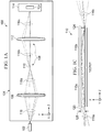
- the exemplary optical imaging system 100 includes a housing 104 in which there is located imaging optics 106, an uni-axial homogenizer 108 (including a rectangular cross-section light pipe 110 and an astigmatic paraxial optic (112), and a detector 114.
- the imaging optics 106 e.g., a convex-shaped lens 106, system of lenses 106) receives light 116 associated with at least a portion of the object light source 102 and outputs light 116a associated with the object light source 102.
- the rectangular cross-section light pipe 110 is positioned to receive the light 116a associated with the object light source 102 from the imaging optics 106 and output light 116b associated with the object light source 102 (see FIGURES 1B-1E ).
- the astigmatic paraxial optic 112 e.g., astigmatic paraxial lens 112
- the detector 114 is positioned to receive the light 116c associated with the object light source 102 from the astigmatic paraxial optic 112 and output the optical image 101 of the object light source 102 (see FIGURE 1E ).
- the optical imaging system 100 can incorporate other components which are well known to those skilled in the art but for clarity only those components which are relevant to the present disclosure are discussed in detail herein.
- a detailed discussion about the uni-axial homogenizer 108 which includes the rectangular cross-section light pipe 110 and the astigmatic paraxial optic 112 is provided below with respect to FIGURES 1B-1E .
- the rectangular cross-section light pipe 110 can be any structure that guides light rays to a specific place in one axis while providing no guidance in a second perpendicular axis. Examples are a rectangular optical waveguide using total internal reflection, a rectangular optical light pipe which is internally hollow but has reflective inner surfaces, or a series of cylindrical lens arrays.
- the rectangular cross-section light pipe 110 is made from two rectangular shaped sections 110a and 110b (more possible) connected so that there is no direct x-axis path, so that there is always homogenization, but it could also be made from one rectangular shaped section (not shown) with a lesser degree of homogenization.
- the rectangular cross-section light pipe 110 has an entrance end 120 (which receives light 116a), a body 122, and an exit end 124 (which outputs light 116b).
- the entrance end 120 has a width 128 sized for homogenizing the received light 116a in an X-axis.
- the entrance end 120 has a height 129 sized for retaining the original spatial and angular image variations in the received light 116a in a Y-axis.
- the body 122 has a predetermined length 131 in a Z-axis.
- Yh exit > Yh entrance + Z light pipe / f / # , where:
- the X-axis, the Y-axis, and the Z-axis described herein and further shown in the drawings are based on the well known three-dimensional Cartesian coordinate system. Furthermore, the drawings for clarity only illustrate a small portion of the light rays associated with the light 116, 116a, 116b, and 116c.
- the Yh(entrance) of the entrance end 120 of the rectangular cross-section light pipe 110 would be selected to match the required image field which prevents vingetting.
- the Yh(exit) of the exit end 124 of the rectangular cross-section light pipe 110 would be selected so that the ray angles of the light 116a entering the rectangular cross-section light pipe 110 would remain unchanged in the Y-Z plane.
- the width 128 of the entrance end 120 of the rectangular cross-section light pipe 110 along the X-axis would be chosen to select the desired image slice.
- the width of the exit end 124 of the rectangular cross-section light pipe 110 along the X-axis would be identical to the width of the entrance end 120 of the rectangular cross-section light pipe 110 along the X-axis.
- the length 131 of the body 122 of the rectangular cross-section light pipe 110 along the Z-axis is chosen to provide the desired degree of homogenization.
- the term homogenization can be can be characterized as follows: where the rectangular cross-section light pipe's entrance end 120 receives the light 116a associated with the object light source 102 and the rectangular cross-section light pipe's body 122 homogenizes the received light 116a associated with the object light source 102 along the X-axis so that a spatial, angular, and polarization distribution of the light 116b on the X-axis which leaves the rectangular cross-section light pipe's exit end 124 is more uniform than the light 116a along the X-axis which is received at the rectangular cross-section light pipe's entrance end 120.
- the term object light source can be characterized as follows: a luminous physical object or an image of such an object created by an imaging system.
- FIGURE 1C there is a top view of the rectangular cross-section light pipe 110 with respect to the XZ plane which illustrates the homogenization of the received light 116a along the X-axis.
- the width 128 of the rectangular cross-section light pipe 110 along the X-axis is 50 ⁇ m and the length 131 of the rectangular cross-section light pipe 100 along the Z-axis is 1 mm.
- the rays of the received light 116a are travelling from left to right.
- configuration of the astigmatic paraxial optic 112 and its position relative to the rectangular cross-section light pipe 100 are important to provide the desired optical image 101 of the object light source 102.
- the astigmatic paraxial optic 112 (e.g., astigmatic paraxial lens 112) would be configured to have a YZ object plane that coincides with the entrance end 120 of the rectangular cross-section light pipe 110.
- the astigmatic paraxial optic 112 would have a XZ object plane that coincides with the exit end 124 of the rectangular cross-section light pipe 110. Plus, the astigmatic paraxial optic 112 would have XZ and YZ image planes which are made to coincide at the detector 114.
- the astigmatic paraxial optic 112 can be configured to meet all of these requirements by selecting the appropriate focal length of the astigmatic paraxial optic 112 in the YZ plane and the appropriate focal length in the XZ plane.
- the astigmatic paraxial optic 112 would be configured to have perfect or substantially perfect (paraxial) imaging in the YZ plane at the plane of the entrance end 120 and in the XZ plane at the plane of the exit end 124.
- An example of the astigmatic paraxial optic 112 could in this application be a cylindrical lens with astigmatism.
- FIGURE 1D there is a magnified side view of the rectangular cross-section light pipe 110 with respect to the YZ plane which illustrates that the spatial and angular image variations of the received light 116a are retained along the Y-axis while also illustrating that there is no homogenization of the received light 116a along the Y-axis but also.
- the height 129 of the rectangular cross-section light pipe 110 along the Y-axis is 1 mm and the length 131 of the rectangular cross-section light pipe 100 along the Z-axis is 1 mm.
- the rays of the received light 116a are travelling from left to right.
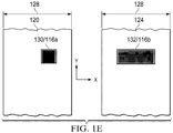
- FIGURE 1E there are two partial end views of the rectangular cross-section light pipe 110 which illustrate an illumination spot 130 (received light 116a) at the entrance end 120 and an illumination spot 132 (output light 116b) obtained at the exit end 124 of the rectangular cross-section light pipe 110.
- the illumination spot 130 is a 20 um square in which homogenization over 50 um which corresponds to the width 128 of the entrance end 120 occurs along the X-axis. No homogenization of the illumination spot 130 occurs along the Y-axis which corresponds to the height 129 of the entrance end 120.
- the illumination spot 132 (output light 116b) at the exit end 124 of the rectangular cross-section light pipe 110 has a rectangular shape that is 20 um along the Y-axis and 50 um along the X-axis.
- the illumination spot 132 is what will be provided by the astigmatic paraxial optic 112 to the detector 114 to form the optical image 101 (see FIGURE 1A ).
- the original square illumination spot 130 has been transformed into a rectangle of illumination 132 which retains the Y dimension of spot 130 but which is spread homogenously over the entire X dimension of the width 128.
- FIGURES 2A-2E there are several diagrams associated with the aforementioned exemplary optical imaging system 100 which instead of providing a single optical image 101 of a single object light source 102 as described above is providing two optical images 101 and 202 of two object light sources 102 and 204 in accordance with an embodiment of the present invention.
- the optical imaging system 100 would include the same components namely the housing 104, the imaging optics 106, the uni-axial homogenizer 108 (including the rectangular cross-section light pipe 110 and the astigmatic paraxial optic 112), and the detector 114 positioned in the same configuration as described above with respect to FIGURES 1A-1E .
- the imaging optics 106 in addition to receiving light 116 (short-dashed lines) associated with at least a portion of the object light source 102 also receives light 206 (long-dashed lines) associated with at least a portion of the other object light source 204 (note: the short-dashed lines and the long-dashed lines are only used to help the reader distinguish the rays of light 116 from the rays of light 206).
- the imaging optics 106 outputs light 116a and 206a associated with the object light sources 102 and 204.
- the rectangular cross-section light pipe 110 is positioned to receive the light 116a and 206a associated with the object light sources 102 and 204 from the imaging optics 106 and output light 116b and 206b associated with the object light sources 102 and 204 (see FIGURES 2B-2E ).
- the astigmatic paraxial optic 112 e.g., astigmatic paraxial lens 112 is positioned to receive the light 116b and 206b associated with the object light sources 102 and 204 from the rectangular cross-section light pipe 110 and output light 116c and 206c associated with the object light sources 102 and 204.
- the detector 114 is positioned to receive the light 116c and 206c associated with the object light sources 102 and 204 from the astigmatic paraxial optic 112 and output optical images 101 and 202 of the object light sources 102 and 204 (see FIGURE 2E ).
- a detailed discussion about the uni-axial homogenizer 108 which includes the rectangular cross-section light pipe 110 and the astigmatic paraxial optic 112 is provided below with respect to FIGURES 2B-2E .
- FIGURE 2B there is a perspective view of the rectangular cross-section light pipe 110 which as described above includes the entrance end 120, the body 122, and the exit end 124.
- the entrance end 120 receives the light 116a associated with the object light source 102 at the illumination spot 130 and receives the light 206a associated with the object light source 204 at the illumination spot 232.
- FIGURE 2C the top view of the rectangular cross-section light pipe 110 with respect to the XZ plane illustrates the homogenization of the received light 116b and 206a along the X-axis.
- the magnified side view of the rectangular cross-section light pipe 110 with respect to the YZ plane illustrates that the spatial and angular image variations of the received light 116a and 206a are retained along the Y-axis while also illustrating that there is no homogenization of the received light 116a and 206a along the Y-axis and also.
- the two end views of the rectangular cross-section light pipe 110 illustrate the illumination spots 130 and 232 (received light 116a and 206a) at the entrance end 120 and the illumination spots 132 and 236 (output light 116b and 206b) obtained at the exit end 124 of the rectangular cross-section light pipe 110.
- the illumination spots 130 and 232 are both 20 um squares which are displaced 30 um along the X-axis and 60 um along the Y-axis. In this case, there was homogenization over 50 um which corresponds to the width 128 of the entrance end 120 and occurs along the X-axis. No homogenization of the illumination spots 130 and 232 occurs along the Y-axis which corresponds to the height 129 of the entrance end 120.
- the illumination spots 132 and 236 (output light 116b and light 206b) at the exit end 124 of the rectangular cross-section light pipe 110 have rectangular shapes that are each 20 um along the Y-axis and 50 um along the X-axis.
- the illumination spots 132 and 236 are what will be provided by the astigmatic paraxial optic 112 to the detector 114 to form the optical images 101 and 202 (see FIGURE 2A ). It should be appreciated that the optical imaging system 100 can also receive light from multiple object light sources (more than the two object light sources 102 and 204) and provide the optical images of those object light sources.
- FIGURES 3A-3C there are photographs illustrating the basic components of an exemplary hyperspectral imaging system 300 configured to provide an optical image 302 which illustrates the spectral features of an object light source 304 in accordance with an embodiment of the present invention.
- the exemplary hyperspectral imaging system 300 includes a housing 306 in which there is located imaging optics 308, an uni-axial homogenizer 310 (which includes a rectangular cross-section light pipe 312 and an astigmatic paraxial optic 314), a diffraction grating 316, a spectrometer optic 318, and a detector 320.
- the imaging optics 308 receives light associated with at least a portion of the object light source 304 and outputs light associated with the object light source 304.
- the rectangular cross-section light pipe 312 is positioned to receive the light associated with the object light source 304 from the imaging optics 308 and output light associated with the object light source 304 (see FIGURES 3B-3C ).
- the astigmatic paraxial optic 314 e.g., paraxial astigmatic imaging incorporated into an Offner primary mirror 315) is positioned to receive the light associated with the object light source 304 from the rectangular cross-section light pipe 312 and reflect light associated with the object light source 304.
- the diffraction grating 316 is positioned to receive the light associated with the object light source 304 from the astigmatic paraxial optic 314, diffract the light associated with the object light source 304, and reflect the diffracted light associated with the object light source 304.
- the spectrometer optic 318 e.g., Offner secondary mirror 318, is positioned to receive the diffracted light associated with the object light source 304 from the diffraction grating 316 and reflect the diffracted light associated with the object light source 304.
- the detector 320 is positioned to receive the diffracted light associated with the object light source 304 from the spectrometer optic 318 and output the optical image 302 which illustrates the spectral features of the object light source 304.
- the uni-axial homogenizer 310 of the present disclosure can be used in the spectrograph 322 of the hyperspectral imaging system 300.
- the rectangular rectangular cross-section light pipe 312 replaces the traditional entrance slit and the astigmatic paraxial optic 314 is built into the design of the traditional spectrometer optic 315.
- the hyperspectral imaging system 300 can also incorporate other components which are well known to those skilled in the art but for clarity only those components which are relevant to the present disclosure are discussed in detail herein.
- FIGURES 3B-3C there are photographs respectively showing a front view and an angled front-side view of the rectangular-shaped rectangular cross-section light pipe 312 which is installed in the exemplary hyperspectral imaging system 300 in accordance with an embodiment of the present invention.
- the rectangular cross-section light pipe 312 is configured to have an entrance end 324 (which receives light associated with the object light source 304), a body 326, and an exit end 328 (which outputs light associated with the object light source 304).
- the entrance end 324 has a width 330 sized for homogenizing the received light in an X-axis.
- the entrance end 324 has a height 332 sized for retaining spatial and angular image variations in the received light in a Y-axis.
- the body 326 has a predetermined length 327 in a Z-axis.
- the astigmatic paraxial optic 314 would be configured to have a YZ object plane that coincides with the entrance end 324 of the rectangular cross-section light pipe 312.
- the astigmatic paraxial optic 314 would have a XZ object plane that coincides with the exit end 328 of the rectangular cross-section light pipe 312. Plus, the astigmatic paraxial optic 314 would have XZ and YZ image planes which are made to coincide at the detector XY plane (320).
- the astigmatic paraxial optic 314 can be configured to meet all of these requirements by selecting the appropriate focal length of the astigmatic paraxial optic 314 in the YZ plane and the appropriate focal length in the XZ plane (see FIGURE 3A ). In other words, the astigmatic paraxial optic 314 would be configured to have perfect or substantially perfect (paraxial) imaging in the YZ plane and in the XZ plane but the focal lengths of the astigmatic paraxial optic 314 would be different in these two planes. It should be appreciated that when an imaging system 300 like a spectrograph follows the uni-axial homogenizer 310, it is rather easy to change the optics in the imaging system so that they still serve their original function, but also serve the function of the astigmatic paraxial lens 314. Then no external astigmatic paraxial lens is needed. Hence, there are two different versions.
- the present disclosure pertains to an optical imaging system 100 in general and, in one particular embodiment, to a hyperspectral imaging system 300 which incorporates a spectrograph 322.
- the performance of the spectrograph-based hyperspectral imaging system 300 is a marked-improvement over the state-of-the-art because the rectangular light pipe 312 replaces the traditional entrance slit and the astigmatic paraxial optic 314 is built into the design of the traditional spectrometer optic.
- the spectrograph-based hyperspectral imaging system 300 with the kaleidoscopic uni- axial homogenizer 310 is configured such that the illumination at the rectangular cross-section light pipe's entrance end 324 is made uniform (homogenized, scattered) across the entrance end's width (one axis, spectral axis) while being able to retain the spatial and angular image variations along the entrance end's length (perpendicular axis, spatial axis).
- the present invention's kaleidoscopic uni-axial homogenizer 310 is not limited to the application in a spectrograph, but it has utility in a wide-variety of devices including, for example, projectors, tracking systems, and optical control systems.
Landscapes
- Physics & Mathematics (AREA)
- Spectroscopy & Molecular Physics (AREA)
- General Physics & Mathematics (AREA)
- Optics & Photonics (AREA)
- Spectrometry And Color Measurement (AREA)
- Investigating Or Analysing Materials By Optical Means (AREA)
- Testing Of Optical Devices Or Fibers (AREA)
Claims (11)
- Optisches Abbildungssystem (100, 300) zum Bereitstellen eines optischen Bildes (101, 302) einer Objektlichtquelle (102, 204, 304), wobei das optische Abbildungssystem umfasst:Abbildungsoptik (106, 308) zum Empfangen von der Objektlichtquelle zugehörigem Licht (116);einen uniaxialen Homogenisator (108, 310), der aufweist:eine Lichtleitung (110, 312) mit rechteckigem Querschnitt, die positioniert wird, um das der Objektlichtquelle zugehörige Licht (116a) von der Abbildungsoptik zu empfangen und konfiguriert wird, um ein Eintrittsende (120), einen Körper (122) und ein Austrittsende (124) aufzuweisen, wobei das Eintrittsende eine Breite (128) aufweist, die zum Homogenisieren des empfangenen Lichts in einer X-Achse ausgelegt wird, wobei das Eintrittsende eine Höhe (129) aufweist, die zum Bewahren räumlicher und winkelförmiger Bildschwankungen in dem empfangenen Licht in einer Y-Achse ausgelegt wird und wobei der Körper eine vorbestimmte Länge (131) in einer Z-Achse aufweist; undeine astigmatische paraxiale Optik (112, 314), die positioniert wird, um das der Objektlichtquelle zugehörige Licht (116b) von der Lichtleitung mit rechteckigem Querschnitt zu empfangen; undeinen Detektor (114, 320), der positioniert wird, um das der Objektlichtquelle zugehörige Licht (116c) von der astigmatischen paraxialen Optik zu empfangen und konfiguriert wird, um das optische Bild der Objektlichtquelle auszugeben;wobei die astigmatische paraxiale Optik konfiguriert wird, eine YZ-Objektebene, die mit dem Eintrittsende der Lichtleitung mit rechteckigem Querschnitt übereinstimmt, eine XZ-Objektebene, die mit dem Austrittsende der Lichtleitung mit rechteckigem Querschnitt übereinstimmt, und eine XZ-Bildebene und eine YZ-Bildebene, die beide an dem Detektor übereinstimmen, aufzuweisen; unddie Höhe (129) des Eintrittsendes, eine Höhe (130) des Austrittsendes und die Länge des Körpers der Lichtleitung mit rechteckigem Querschnitt ausgelegt werden, um dem Folgenden zu genügen:
 Z(Lichtleitung) die Länge der Lichtleitung ist,Yh(Austritt) die Höhe des Austrittsendes ist,Yh(Eintritt) die Höhe des Eintrittsendes ist, und1/f/# das Doppelte einer Steigung eines maximalen Winkels des Lichts ist, das die Lichtleitung mit rechteckigem Querschnitt durchläuft.
 - Optisches Abbildungssystem nach Anspruch 1, wobei die Lichtleitung mit rechteckigem Querschnitt aufweist:das Eintrittsende weist in der Y-Achse die Höhe auf, die ausgelegt wird, mit einem gewünschten Bildbereich an dem Detektor übereinzustimmen;das Austrittsende weist in der Y-Achse eine Höhe auf, die ausgelegt wird, dass Winkel des an dem Eintrittsende empfangenen Lichts in einer YZ-Ebene innerhalb des Körpers der Lichtleitung mit rechteckigem Querschnitt unverändert bleiben; unddas Eintrittsende weist in der X-Achse die Breite auf, die ausgelegt wird, um einen gewünschten Bildausschnitt der Objektlichtquelle bereitzustellen.
- Optisches Abbildungssystem nach Anspruch 1, wobei die Lichtleitung mit rechteckigem Querschnitt einen oder mehrere verbundene rechteckige Abschnitte (110a, 110b) umfasst.
- Optisches Abbildungssystem nach Anspruch 1, wobei die Lichtleitung mit rechteckigem Querschnitt einen rechteckigen optischen Wellenleiter durch Verwenden vollständiger interner Reflektion oder eine rechteckige optische Lichtleitung umfasst, die innerlich hohl ist, aber reflektierende Innenoberfläche aufweist.
- Optisches Abbildungssystem nach Anspruch 1, wobei die astigmatische paraxiale Optik eine zylindrische Linse mit Astigmatismus ist.
- Optisches Abbildungssystem nach Anspruch 1, wobei die Breite des Eintrittsendes unterschiedlich zu einer Breite des Austrittsendes ist.
- Optisches Abbildungssystem nach Anspruch 1, wobei die Abbildungsoptik, der uniaxiale Homogenisator und der Detektor konfiguriert werden, um ein optisches Bild einer weiteren Objektlichtquelle (204) in derselben Weise und derselben Zeit bereitzustellen, wie sie das optische Bild der Objektlichtquelle bereitstellen.
- Verfahren zum Herstellen eines optischen Abbildungssystem (100, 300), das ein optisches Bild (101, 302) einer Objektlichtquelle (102, 204, 304) bereitstellt, wobei das Verfahren die Schritte umfasst:Bereitstellen von Abbildungsoptik (106, 308), die konfiguriert wird, um der Objektlichtquelle zugehöriges Licht (116) zu empfangen;Bereitstellen eines uniaxialen Homogenisators (108, 310), der aufweist:eine Lichtleitung (110, 312) mit rechteckigem Querschnitt, die positioniert wird, um das der Objektlichtquelle zugehörige Licht (116a) von der Abbildungsoptik zu empfangen und konfiguriert wird, um ein Eintrittsende (120), einen Körper (122) und ein Austrittsende (124) aufzuweisen, wobei das Eintrittsende eine Breite (128) aufweist, die zum Homogenisieren des empfangenen Lichts in einer X-Achse ausgelegt wird, wobei das Eintrittsende eine Höhe (129) aufweist, die zum Bewahren räumlicher und winkelförmiger Bildschwankungen in dem empfangenen Licht in einer Y-Achse ausgelegt wird und wobei der Körper eine vorbestimmte Länge (131) in einer Z-Achse aufweist; undeine astigmatische paraxiale Optik (112, 314), die positioniert wird, um das der Objektlichtquelle zugehörige Licht (116b) von der Lichtleitung mit rechteckigem Querschnitt zu empfangen; undBereitstellen eines Detektors (114, 320), der positioniert wird, um das der Objektlichtquelle zugehörige Licht (116c) von der astigmatischen paraxialen Optik zu empfangen und konfiguriert wird, um das optische Bild der Objektlichtquelle auszugeben;wobei der Schritt des Bereitstellens der astigmatischen paraxialen Optik des Weiteren einen Schritt des Gestaltens der astigmatischen paraxialen Optik aufweist, eine YZ- Objektebene, die mit dem Eintrittsende der Lichtleitung mit rechteckigem Querschnitt übereinstimmt, eine XZ-Objektebene, die mit dem Austrittsende der Lichtleitung mit rechteckigem Querschnitt übereinstimmt, und eine XZ-Bildebene und eine YZ-Bildebene zu haben, die beide an dem Detektor übereinstimmen; unddie Höhe (129) des Eintrittsendes, eine Höhe (130) des Austrittsendes und die Länge des Körpers der Lichtleitung mit rechteckigem Querschnitt ausgelegt werden, um dem Folgenden zu genügen:
 Z(Lichtleitung) die Länge der Lichtleitung ist,Yh(Austritt) die Höhe des Austrittsendes ist,Yh(Eintritt) die Höhe des Eintrittsendes ist, und1/f/# das Doppelte einer Steigung eines maximalen Winkels des Lichts ist, das die Lichtleitung mit rechteckigem Querschnitt durchläuft.
 - Verfahren nach Anspruch 8, wobei der Schritt des Bereitstellens des uniaxialen Homogenisators des Weiteren einen Schritt des Gestaltens der Lichtleitung mit rechteckigem Querschnitt aufweist, sodass:das Eintrittsende in der Y-Achse die Höhe aufweist, die ausgelegt wird, mit einem gewünschten Bildbereich an dem Detektor übereinzustimmen;das Austrittsende in der Y-Achse eine Höhe aufweist, die ausgelegt wird, dass Winkel des an dem Eintrittsende empfangenen Lichts in einer YZ-Ebene innerhalb des Körpers der Lichtleitung mit rechteckigem Querschnitt unverändert bleiben; unddas Eintrittsende in der X-Achse die Breite aufweist, die ausgelegt wird, um einen gewünschten Bildausschnitt der Objektlichtquelle bereitzustellen.
- Verfahren nach Anspruch 9, wobei die Abbildungsoptik, der uniaxiale Homogenisator und der Detektor konfiguriert werden, um ein optisches Bild einer weiteren Objektlichtquelle in derselben Weise und derselben Zeit bereitzustellen, wie sie das optische Bild der Objektlichtquelle bereitstellen.
- Hyperspektrales Abbildungssystem (300) zum Bereitstellen eines optischen Bildes (302) einer Objektlichtquelle (304), wobei das hyperspektrale Abbildungssystem umfasst
ein optisches Abbildungssystem (300) zum Bereitstellen eines optischen Bildes (302) nach Anspruch 1;
wobei der uniaxiale Homogenisator (310) des Weiteren umfasst: ein Beugungsgitter (316), das positioniert wird, um das der Objektlichtquelle zugehörige Licht von der astigmatischen paraxialen Optik zu empfangen; und
eine Spektrometeroptik (318), die positioniert wird, um das der Objektlichtquelle zugehörige Licht von dem Beugungsgitter zu empfangen; und
der Detektor (320) wird positioniert, um das der Objektlichtquelle zugehörige Licht von der Spektrometeroptik zu empfangen und konfiguriert, um das optische Bild der Objektlichtquelle auszugeben.
Applications Claiming Priority (2)
| Application Number | Priority Date | Filing Date | Title |
|---|---|---|---|
| US201261653668P | 2012-05-31 | 2012-05-31 | |
| PCT/US2013/043018 WO2013181203A1 (en) | 2012-05-31 | 2013-05-29 | Optical imaging system that incorporates an uni-axial optical homogenizer |
Publications (2)
| Publication Number | Publication Date |
|---|---|
| EP2856094A1 EP2856094A1 (de) | 2015-04-08 |
| EP2856094B1 true EP2856094B1 (de) | 2018-03-07 |
Family
ID=48614163
Family Applications (1)
| Application Number | Title | Priority Date | Filing Date |
|---|---|---|---|
| EP13728613.4A Not-in-force EP2856094B1 (de) | 2012-05-31 | 2013-05-29 | Optisches bildgebungssystem mit einem integrierten uniaxialen optischen homogenisator |
Country Status (4)
| Country | Link |
|---|---|
| US (1) | US9583524B2 (de) |
| EP (1) | EP2856094B1 (de) |
| JP (1) | JP6291483B2 (de) |
| WO (1) | WO2013181203A1 (de) |
Families Citing this family (4)
| Publication number | Priority date | Publication date | Assignee | Title |
|---|---|---|---|---|
| JP6251073B2 (ja) * | 2014-02-05 | 2017-12-20 | 浜松ホトニクス株式会社 | 分光器、及び分光器の製造方法 |
| US20160209330A1 (en) * | 2015-01-21 | 2016-07-21 | Protrustech Co., Ltd | Integrated raman spectrometer and modularized laser module |
| US10897585B2 (en) * | 2017-12-07 | 2021-01-19 | Corning Incorporated | Hyperspectral imaging system and method for providing a hyperspectral image of an area of a remote object |
| US20250198836A1 (en) * | 2023-12-14 | 2025-06-19 | Kla Corporation | Diffraction-Based Illumination Sampling |
Family Cites Families (13)
| Publication number | Priority date | Publication date | Assignee | Title |
|---|---|---|---|---|
| US3624421A (en) * | 1970-06-11 | 1971-11-30 | Research Corp | Tunable raman laser |
| US5026160A (en) * | 1989-10-04 | 1991-06-25 | The United States Of America As Represented By The Secretary Of The Navy | Monolithic optical programmable spectrograph (MOPS) |
| US5257085A (en) * | 1991-04-24 | 1993-10-26 | Kaman Aerospace Corporation | Spectrally dispersive imaging lidar system |
| US20020036234A1 (en) * | 2000-03-31 | 2002-03-28 | Hong Tang | Spectral data collector which includes a lambertian reflector |
| US6969177B2 (en) * | 2001-03-23 | 2005-11-29 | Wavien, Inc. | Polarization recovery system using redirection |
| US7327916B2 (en) * | 2003-03-11 | 2008-02-05 | Semiconductor Energy Laboratory Co., Ltd. | Beam Homogenizer, laser irradiation apparatus, and method of manufacturing a semiconductor device |
| US7210820B2 (en) | 2003-05-07 | 2007-05-01 | Resonetics, Inc. | Methods and apparatuses for homogenizing light |
| WO2004106983A2 (en) * | 2003-05-22 | 2004-12-09 | Optical Research Associates | Illumination in optical systems |
| CA2581668A1 (en) * | 2003-09-26 | 2005-04-07 | Tidal Photonics, Inc | Apparatus and methods relating to expanded dynamic range imaging endoscope systems |
| US7245373B2 (en) * | 2004-04-26 | 2007-07-17 | University Of Massachusetts | Spectrometer system for optical reflectance measurements |
| US7910499B2 (en) * | 2004-11-12 | 2011-03-22 | Applied Materials, Inc. | Autofocus for high power laser diode based annealing system |
| US7355800B2 (en) * | 2005-02-07 | 2008-04-08 | Coherent, Inc. | Apparatus for projecting a line of light from a diode-laser array |
| US20120212737A1 (en) * | 2011-02-23 | 2012-08-23 | Comstock Ii Lovell E | Optical homogenizing elements to reduce spectral noise in hyperspectral imaging system |
-
2013
- 2013-05-29 EP EP13728613.4A patent/EP2856094B1/de not_active Not-in-force
- 2013-05-29 WO PCT/US2013/043018 patent/WO2013181203A1/en not_active Ceased
- 2013-05-29 JP JP2015515134A patent/JP6291483B2/ja not_active Expired - Fee Related
- 2013-05-30 US US13/905,402 patent/US9583524B2/en not_active Expired - Fee Related
Also Published As
| Publication number | Publication date |
|---|---|
| JP6291483B2 (ja) | 2018-03-14 |
| US9583524B2 (en) | 2017-02-28 |
| JP2015519611A (ja) | 2015-07-09 |
| US20130321808A1 (en) | 2013-12-05 |
| WO2013181203A1 (en) | 2013-12-05 |
| EP2856094A1 (de) | 2015-04-08 |
Similar Documents
| Publication | Publication Date | Title |
|---|---|---|
| US7961398B2 (en) | Multiple image camera and lens system | |
| US10288481B2 (en) | Spectrometer for generating a two dimensional spectrum | |
| Le Fevre et al. | CFHT MOS/SIS spectrograph performance | |
| EP2856094B1 (de) | Optisches bildgebungssystem mit einem integrierten uniaxialen optischen homogenisator | |
| EP4012361A2 (de) | Optische formen für mehrkanalige dispersive doppelpass-spektrometer | |
| WO2019035047A1 (en) | SPECTROMETER SCALE COMPACT FREE SHAPE | |
| KR20160054580A (ko) | 조명 시스템 | |
| Eastman et al. | NRES: the network of robotic Echelle spectrographs | |
| Spiga et al. | Optical simulations for the laboratory-based expanded and collimated x-ray beam facility BEaTriX | |
| Sheinis et al. | The gemini high-resolution optical spectrograph (ghost) | |
| US11086111B1 (en) | Telecentric reflective imager | |
| US12242077B1 (en) | Wide spatial field optical systems | |
| Caron et al. | Slit homogenizers for Earth observation spectrometers: overview on performance, present and future designs | |
| Kushibiki et al. | Development of a near-infrared wide-field integral field unit by ultra-precision diamond cutting | |
| Vives et al. | Original image slicer designed for integral field spectroscopy with the near-infrared spectrograph for the James Webb Space Telescope | |
| Zhang et al. | The infrared imaging spectrograph (IRIS) for TMT: design of image slicer | |
| US10107682B1 (en) | Non-circular aperture reflective imager | |
| Greco et al. | Optical design of a near-infrared imaging spectropolarimeter for the Advanced Technology Solar Telescope | |
| EP3401656A1 (de) | Korrektur einer gekrümmten projektion eines spektrometereintrittsspalts | |
| Laurent et al. | Collimating slicer for optical integral field spectroscopy | |
| RU2567447C1 (ru) | Зеркальный автоколлимационный спектрометр | |
| Lee et al. | How to align replicated fiber-IFU spectrographs? A decadal journey and evolution through aligning VIRUS-P, VIRUS, LRS2, and VIRUS2 spectrographs | |
| US11480806B2 (en) | Cassegrain telescope with a segmented focal plane | |
| Kang et al. | Plug-in cross-dispersing module for the Large Binocular Telescope’s infrared spectrograph LUCI | |
| RU2567448C1 (ru) | Зеркальный спектрометр |
Legal Events
| Date | Code | Title | Description |
|---|---|---|---|
| PUAI | Public reference made under article 153(3) epc to a published international application that has entered the european phase |
Free format text: ORIGINAL CODE: 0009012 |
|
| 17P | Request for examination filed |
Effective date: 20141218 |
|
| AK | Designated contracting states |
Kind code of ref document: A1 Designated state(s): AL AT BE BG CH CY CZ DE DK EE ES FI FR GB GR HR HU IE IS IT LI LT LU LV MC MK MT NL NO PL PT RO RS SE SI SK SM TR |
|
| AX | Request for extension of the european patent |
Extension state: BA ME |
|
| DAX | Request for extension of the european patent (deleted) | ||
| 17Q | First examination report despatched |
Effective date: 20161222 |
|
| REG | Reference to a national code |
Ref country code: DE Ref legal event code: R079 Ref document number: 602013034016 Country of ref document: DE Free format text: PREVIOUS MAIN CLASS: G01J0003020000 Ipc: H01L0027146000 |
|
| RIC1 | Information provided on ipc code assigned before grant |
Ipc: H01L 27/146 20060101AFI20170810BHEP Ipc: G01J 3/18 20060101ALI20170810BHEP Ipc: G01J 1/04 20060101ALI20170810BHEP Ipc: G01J 3/28 20060101ALI20170810BHEP Ipc: G01J 3/02 20060101ALI20170810BHEP Ipc: G02B 27/09 20060101ALI20170810BHEP |
|
| GRAP | Despatch of communication of intention to grant a patent |
Free format text: ORIGINAL CODE: EPIDOSNIGR1 |
|
| INTG | Intention to grant announced |
Effective date: 20171128 |
|
| GRAJ | Information related to disapproval of communication of intention to grant by the applicant or resumption of examination proceedings by the epo deleted |
Free format text: ORIGINAL CODE: EPIDOSDIGR1 |
|
| GRAR | Information related to intention to grant a patent recorded |
Free format text: ORIGINAL CODE: EPIDOSNIGR71 |
|
| GRAS | Grant fee paid |
Free format text: ORIGINAL CODE: EPIDOSNIGR3 |
|
| GRAA | (expected) grant |
Free format text: ORIGINAL CODE: 0009210 |
|
| INTC | Intention to grant announced (deleted) | ||
| INTG | Intention to grant announced |
Effective date: 20180125 |
|
| AK | Designated contracting states |
Kind code of ref document: B1 Designated state(s): AL AT BE BG CH CY CZ DE DK EE ES FI FR GB GR HR HU IE IS IT LI LT LU LV MC MK MT NL NO PL PT RO RS SE SI SK SM TR |
|
| REG | Reference to a national code |
Ref country code: GB Ref legal event code: FG4D |
|
| REG | Reference to a national code |
Ref country code: CH Ref legal event code: EP Ref country code: AT Ref legal event code: REF Ref document number: 977411 Country of ref document: AT Kind code of ref document: T Effective date: 20180315 |
|
| REG | Reference to a national code |
Ref country code: IE Ref legal event code: FG4D |
|
| REG | Reference to a national code |
Ref country code: DE Ref legal event code: R096 Ref document number: 602013034016 Country of ref document: DE |
|
| REG | Reference to a national code |
Ref country code: NL Ref legal event code: MP Effective date: 20180307 |
|
| REG | Reference to a national code |
Ref country code: LT Ref legal event code: MG4D |
|
| PG25 | Lapsed in a contracting state [announced via postgrant information from national office to epo] |
Ref country code: LT Free format text: LAPSE BECAUSE OF FAILURE TO SUBMIT A TRANSLATION OF THE DESCRIPTION OR TO PAY THE FEE WITHIN THE PRESCRIBED TIME-LIMIT Effective date: 20180307 Ref country code: CY Free format text: LAPSE BECAUSE OF FAILURE TO SUBMIT A TRANSLATION OF THE DESCRIPTION OR TO PAY THE FEE WITHIN THE PRESCRIBED TIME-LIMIT Effective date: 20180307 Ref country code: HR Free format text: LAPSE BECAUSE OF FAILURE TO SUBMIT A TRANSLATION OF THE DESCRIPTION OR TO PAY THE FEE WITHIN THE PRESCRIBED TIME-LIMIT Effective date: 20180307 Ref country code: ES Free format text: LAPSE BECAUSE OF FAILURE TO SUBMIT A TRANSLATION OF THE DESCRIPTION OR TO PAY THE FEE WITHIN THE PRESCRIBED TIME-LIMIT Effective date: 20180307 Ref country code: FI Free format text: LAPSE BECAUSE OF FAILURE TO SUBMIT A TRANSLATION OF THE DESCRIPTION OR TO PAY THE FEE WITHIN THE PRESCRIBED TIME-LIMIT Effective date: 20180307 Ref country code: NO Free format text: LAPSE BECAUSE OF FAILURE TO SUBMIT A TRANSLATION OF THE DESCRIPTION OR TO PAY THE FEE WITHIN THE PRESCRIBED TIME-LIMIT Effective date: 20180607 |
|
| REG | Reference to a national code |
Ref country code: AT Ref legal event code: MK05 Ref document number: 977411 Country of ref document: AT Kind code of ref document: T Effective date: 20180307 |
|
| PG25 | Lapsed in a contracting state [announced via postgrant information from national office to epo] |
Ref country code: RS Free format text: LAPSE BECAUSE OF FAILURE TO SUBMIT A TRANSLATION OF THE DESCRIPTION OR TO PAY THE FEE WITHIN THE PRESCRIBED TIME-LIMIT Effective date: 20180307 Ref country code: BG Free format text: LAPSE BECAUSE OF FAILURE TO SUBMIT A TRANSLATION OF THE DESCRIPTION OR TO PAY THE FEE WITHIN THE PRESCRIBED TIME-LIMIT Effective date: 20180607 Ref country code: GR Free format text: LAPSE BECAUSE OF FAILURE TO SUBMIT A TRANSLATION OF THE DESCRIPTION OR TO PAY THE FEE WITHIN THE PRESCRIBED TIME-LIMIT Effective date: 20180608 Ref country code: LV Free format text: LAPSE BECAUSE OF FAILURE TO SUBMIT A TRANSLATION OF THE DESCRIPTION OR TO PAY THE FEE WITHIN THE PRESCRIBED TIME-LIMIT Effective date: 20180307 Ref country code: SE Free format text: LAPSE BECAUSE OF FAILURE TO SUBMIT A TRANSLATION OF THE DESCRIPTION OR TO PAY THE FEE WITHIN THE PRESCRIBED TIME-LIMIT Effective date: 20180307 |
|
| PG25 | Lapsed in a contracting state [announced via postgrant information from national office to epo] |
Ref country code: NL Free format text: LAPSE BECAUSE OF FAILURE TO SUBMIT A TRANSLATION OF THE DESCRIPTION OR TO PAY THE FEE WITHIN THE PRESCRIBED TIME-LIMIT Effective date: 20180307 Ref country code: AL Free format text: LAPSE BECAUSE OF FAILURE TO SUBMIT A TRANSLATION OF THE DESCRIPTION OR TO PAY THE FEE WITHIN THE PRESCRIBED TIME-LIMIT Effective date: 20180307 Ref country code: PL Free format text: LAPSE BECAUSE OF FAILURE TO SUBMIT A TRANSLATION OF THE DESCRIPTION OR TO PAY THE FEE WITHIN THE PRESCRIBED TIME-LIMIT Effective date: 20180307 Ref country code: RO Free format text: LAPSE BECAUSE OF FAILURE TO SUBMIT A TRANSLATION OF THE DESCRIPTION OR TO PAY THE FEE WITHIN THE PRESCRIBED TIME-LIMIT Effective date: 20180307 Ref country code: EE Free format text: LAPSE BECAUSE OF FAILURE TO SUBMIT A TRANSLATION OF THE DESCRIPTION OR TO PAY THE FEE WITHIN THE PRESCRIBED TIME-LIMIT Effective date: 20180307 Ref country code: IT Free format text: LAPSE BECAUSE OF FAILURE TO SUBMIT A TRANSLATION OF THE DESCRIPTION OR TO PAY THE FEE WITHIN THE PRESCRIBED TIME-LIMIT Effective date: 20180307 |
|
| PG25 | Lapsed in a contracting state [announced via postgrant information from national office to epo] |
Ref country code: SK Free format text: LAPSE BECAUSE OF FAILURE TO SUBMIT A TRANSLATION OF THE DESCRIPTION OR TO PAY THE FEE WITHIN THE PRESCRIBED TIME-LIMIT Effective date: 20180307 Ref country code: CZ Free format text: LAPSE BECAUSE OF FAILURE TO SUBMIT A TRANSLATION OF THE DESCRIPTION OR TO PAY THE FEE WITHIN THE PRESCRIBED TIME-LIMIT Effective date: 20180307 Ref country code: AT Free format text: LAPSE BECAUSE OF FAILURE TO SUBMIT A TRANSLATION OF THE DESCRIPTION OR TO PAY THE FEE WITHIN THE PRESCRIBED TIME-LIMIT Effective date: 20180307 Ref country code: SM Free format text: LAPSE BECAUSE OF FAILURE TO SUBMIT A TRANSLATION OF THE DESCRIPTION OR TO PAY THE FEE WITHIN THE PRESCRIBED TIME-LIMIT Effective date: 20180307 |
|
| REG | Reference to a national code |
Ref country code: DE Ref legal event code: R097 Ref document number: 602013034016 Country of ref document: DE |
|
| REG | Reference to a national code |
Ref country code: CH Ref legal event code: PL |
|
| PG25 | Lapsed in a contracting state [announced via postgrant information from national office to epo] |
Ref country code: PT Free format text: LAPSE BECAUSE OF FAILURE TO SUBMIT A TRANSLATION OF THE DESCRIPTION OR TO PAY THE FEE WITHIN THE PRESCRIBED TIME-LIMIT Effective date: 20180709 |
|
| PLBE | No opposition filed within time limit |
Free format text: ORIGINAL CODE: 0009261 |
|
| STAA | Information on the status of an ep patent application or granted ep patent |
Free format text: STATUS: NO OPPOSITION FILED WITHIN TIME LIMIT |
|
| REG | Reference to a national code |
Ref country code: BE Ref legal event code: MM Effective date: 20180531 |
|
| PG25 | Lapsed in a contracting state [announced via postgrant information from national office to epo] |
Ref country code: MC Free format text: LAPSE BECAUSE OF FAILURE TO SUBMIT A TRANSLATION OF THE DESCRIPTION OR TO PAY THE FEE WITHIN THE PRESCRIBED TIME-LIMIT Effective date: 20180307 Ref country code: DK Free format text: LAPSE BECAUSE OF FAILURE TO SUBMIT A TRANSLATION OF THE DESCRIPTION OR TO PAY THE FEE WITHIN THE PRESCRIBED TIME-LIMIT Effective date: 20180307 |
|
| 26N | No opposition filed |
Effective date: 20181210 |
|
| REG | Reference to a national code |
Ref country code: IE Ref legal event code: MM4A |
|
| GBPC | Gb: european patent ceased through non-payment of renewal fee |
Effective date: 20180607 |
|
| PG25 | Lapsed in a contracting state [announced via postgrant information from national office to epo] |
Ref country code: SI Free format text: LAPSE BECAUSE OF FAILURE TO SUBMIT A TRANSLATION OF THE DESCRIPTION OR TO PAY THE FEE WITHIN THE PRESCRIBED TIME-LIMIT Effective date: 20180307 Ref country code: CH Free format text: LAPSE BECAUSE OF NON-PAYMENT OF DUE FEES Effective date: 20180531 Ref country code: LI Free format text: LAPSE BECAUSE OF NON-PAYMENT OF DUE FEES Effective date: 20180531 |
|
| PG25 | Lapsed in a contracting state [announced via postgrant information from national office to epo] |
Ref country code: LU Free format text: LAPSE BECAUSE OF NON-PAYMENT OF DUE FEES Effective date: 20180529 |
|
| PG25 | Lapsed in a contracting state [announced via postgrant information from national office to epo] |
Ref country code: GB Free format text: LAPSE BECAUSE OF NON-PAYMENT OF DUE FEES Effective date: 20180607 Ref country code: FR Free format text: LAPSE BECAUSE OF NON-PAYMENT OF DUE FEES Effective date: 20180531 Ref country code: IE Free format text: LAPSE BECAUSE OF NON-PAYMENT OF DUE FEES Effective date: 20180529 |
|
| PG25 | Lapsed in a contracting state [announced via postgrant information from national office to epo] |
Ref country code: BE Free format text: LAPSE BECAUSE OF NON-PAYMENT OF DUE FEES Effective date: 20180531 |
|
| PG25 | Lapsed in a contracting state [announced via postgrant information from national office to epo] |
Ref country code: MT Free format text: LAPSE BECAUSE OF NON-PAYMENT OF DUE FEES Effective date: 20180529 |
|
| PG25 | Lapsed in a contracting state [announced via postgrant information from national office to epo] |
Ref country code: TR Free format text: LAPSE BECAUSE OF FAILURE TO SUBMIT A TRANSLATION OF THE DESCRIPTION OR TO PAY THE FEE WITHIN THE PRESCRIBED TIME-LIMIT Effective date: 20180307 |
|
| PG25 | Lapsed in a contracting state [announced via postgrant information from national office to epo] |
Ref country code: MK Free format text: LAPSE BECAUSE OF NON-PAYMENT OF DUE FEES Effective date: 20180307 Ref country code: HU Free format text: LAPSE BECAUSE OF FAILURE TO SUBMIT A TRANSLATION OF THE DESCRIPTION OR TO PAY THE FEE WITHIN THE PRESCRIBED TIME-LIMIT; INVALID AB INITIO Effective date: 20130529 |
|
| PG25 | Lapsed in a contracting state [announced via postgrant information from national office to epo] |
Ref country code: IS Free format text: LAPSE BECAUSE OF FAILURE TO SUBMIT A TRANSLATION OF THE DESCRIPTION OR TO PAY THE FEE WITHIN THE PRESCRIBED TIME-LIMIT Effective date: 20180707 |
|
| PGFP | Annual fee paid to national office [announced via postgrant information from national office to epo] |
Ref country code: DE Payment date: 20200417 Year of fee payment: 8 |
|
| REG | Reference to a national code |
Ref country code: DE Ref legal event code: R119 Ref document number: 602013034016 Country of ref document: DE |
|
| PG25 | Lapsed in a contracting state [announced via postgrant information from national office to epo] |
Ref country code: DE Free format text: LAPSE BECAUSE OF NON-PAYMENT OF DUE FEES Effective date: 20211201 |