EP2856446B1 - Vorrichtung, system und verfahren zum überwachen eines vorgegebenen raums - Google Patents
Vorrichtung, system und verfahren zum überwachen eines vorgegebenen raums Download PDFInfo
- Publication number
- EP2856446B1 EP2856446B1 EP13737394.0A EP13737394A EP2856446B1 EP 2856446 B1 EP2856446 B1 EP 2856446B1 EP 13737394 A EP13737394 A EP 13737394A EP 2856446 B1 EP2856446 B1 EP 2856446B1
- Authority
- EP
- European Patent Office
- Prior art keywords
- movement
- zone
- space
- unauthorised
- authorised
- Prior art date
- Legal status (The legal status is an assumption and is not a legal conclusion. Google has not performed a legal analysis and makes no representation as to the accuracy of the status listed.)
- Not-in-force
Links
Images


Classifications
-
- G—PHYSICS
- G08—SIGNALLING
- G08B—SIGNALLING SYSTEMS, e.g. PERSONAL CALLING SYSTEMS; ORDER TELEGRAPHS; ALARM SYSTEMS
- G08B13/00—Burglar, theft or intruder alarms
-
- G—PHYSICS
- G08—SIGNALLING
- G08B—SIGNALLING SYSTEMS, e.g. PERSONAL CALLING SYSTEMS; ORDER TELEGRAPHS; ALARM SYSTEMS
- G08B13/00—Burglar, theft or intruder alarms
- G08B13/18—Actuation by interference with heat, light, or radiation of shorter wavelength; Actuation by intruding sources of heat, light, or radiation of shorter wavelength
- G08B13/189—Actuation by interference with heat, light, or radiation of shorter wavelength; Actuation by intruding sources of heat, light, or radiation of shorter wavelength using passive radiation detection systems
- G08B13/19—Actuation by interference with heat, light, or radiation of shorter wavelength; Actuation by intruding sources of heat, light, or radiation of shorter wavelength using passive radiation detection systems using infrared-radiation detection systems
Definitions
- This invention relates to a device, a system and a method for monitoring a predetermined space, that is, a monitoring area (both inside and outside of buildings).
- Volumetric type monitoring systems are known in the sector in question which allow predetermined zones to be monitored.
- These monitoring systems are generally equipped with volumetric sensors which allow the accesses to the building (for example, the doors, windows etc.) to be monitored.
- a first drawback of this type of security/monitoring system is due to the fact that these systems do not distinguish whether the person accessing the monitored space is authorised or not to access the space.
- volumetric detection systems can only be activated in the absence of persons in the protected area and they must therefore be deactivated if that is not the case.
- Document WO2006/093527 shows an autonomous defense of a facility having an adjacent restricted access area.
- detection devices and warning devices as well as deterrent devices.
- the detection devices are radar units and cameras that detect an intruder within the restricted access area.
- the intruder Prior to the intruder entering the restricted access area, the intruder is tracked. When the intruder approaches the facility at a predetermined distance, a warning is provided. If the intruder approaches closer to the facility, then a deterrent is provided. The deterrent can be loud uncomfortable sounds or non-lethal munitions. If the intruder continues to approach the facility, the lethal responses can be delivered in the form of lethal sound or lethal weapons.
- Document WO2011/005074 shows a surveillance system comprising one or more video camera capturing surveillance scene images of a surveillance area, a control console having a display unit, wherein said control console receives video signal of video images sent by said video camera in order to display said surveillance scene images on said display unit, and a programmed instruction operating on board said control console, wherein said programmed instruction having a first function to define one or more secured zone within said surveillance scene, said secured zone is an enclosed area having curve boundary and a security index, and said programmed instruction computes a response based on said security index when a non-permitted object is within said secured zone.
- Document CA2634261 shows a remote area monitoring system (RAMS) for detecting movement in a disallowed direction through a passageway.
- the RAMS monitors two volumetric spaces that are established by the system, both of which spaces are defined with respect to depth, width, and height. Both a warning zone and an alarm zone are defined for each space.
- the warning zone protects against inadvertent incursion into the protected spaces; while the alarm zone protects against intentional intrusions thereinto by movement in the disallowed direction.
- the RAMS automatically monitors both zones and does not require human vigilance to detect and warn of an incursion or intrusion. Human traffic, in both directions through the zones, is monitored; as well as the movement of objects.
- Movement of humans is detected using a sensor employing machine vision technology including multiple overhead modules linked together so to cover the passageway through which pedestrians travel. The zones covered by the modules overlap so to insure that there are no gaps in coverage.
- a sensor employs near infrared imaging techniques to detect thrown or tossed objects.
- a workstation includes a display where alarm events are recorded and logged. The workstation also includes recording and printing equipment to aid in apprehension of an intruder.
- the aim of the present invention is, therefore, to overcome these drawbacks by providing a device and a system for monitoring a predetermined space (both inside and outside a building).
- Another aim is to provide a process for monitoring a predetermined space comprising a first and a second zone.
- the invention comprises a device 1 for monitoring a predetermined zone or space V (these two terms are used below without distinction).
- the predetermined space V in the example shown in the accompanying figures, comprises a first "authorised" zone 3A and a second "unauthorised” zone 2NA.
- the first zone 3A is delimited by the dashed lines labelled 3, whilst the second zone 2NA is delimited by the dashed lines labelled 2.
- the first zone 3A will hereafter also be referred to as “authorised”, whilst the second zone 2NA will hereafter also be referred to as “unauthorised”.
- the monitoring device in the simplest embodiment, comprises a first volumetric sensor SV1 for detecting a first movement signal S1 in the first zone 3A of the space.
- the first zone 2A is the zone monitored by the first sensor SV1: in other words, by changing the orientation / positioning of the first sensor S1 the boundaries of the first zone are modified.
- the device 1 in its simplest embodiment comprises a second volumetric sensor SV2 for detecting a second movement signal S2 in a second zone 2NA of the monitored space.
- the second zone 2NA is the zone monitored by the second sensor SV2: in other words, by changing the orientation / positioning of the second sensor SV2 the boundaries of the second zone are modified.
- the device 1 can also comprise more than two sensors.
- each sensor can be designed for monitoring a zone of the authorised type or a zone of the unauthorised type.
- the sensors SV1, SV2 are volumetric type sensors.
- the sensors SV1, SV2 are passive infra-red (PIR) sensors.
- PIR passive infra-red
- volumetric sensor such as, for example, microwave or ultrasound sensors, or combinations of them.
- the sensors SV1, SV2 comprise optics O1, O2 of the mirror type, that is, optical cones.
- the type of optics O1, O2 also allows the flexibility of the device 1 to be increased as it allows the degree of overlapping of the spaces monitored by the sensors SV1, SV2 to be modified and to adapt the configuration of the device 1 to every type of environment.
- the sensors can also not be provided with optics; the optics are preferably present in the case of PIR type sensors.
- the sensors are associated with an adjustable support, to allow adjustment of the position.
- each sensor (SV1, SV2) is connected to the circuit C by electrical connecting means.
- the sensors SV1, SV2 can provide an analogue or digital signal (S1, S2) to the processing means (which are described below) (that is, the sensors SV1, SV2 can be of the analogue or digital type).
- the signal S1, S2 is analogue, it is possible, so as to prevent potential electromagnetic disturbances from altering the levels of the signal S1, S2, to amplify the signal using an amplification circuit located in the support of the sensor SV1, SV2 and close to the sensor; or, alternatively, it is possible to use a piece of shielded cable.
- the amplifier is preferably directly integrated in the sensor SV1, SV2.
- the device 1 comprises means of processing the signals S1, S2 of the sensors.
- the sensors SV1, SV2 and the processing means are integrated inside the same box-shaped container SC (clearly shown in Figure 4 ).
- the processing means ME are designed for implementing the method / algorithm shown in Figure 5 and described below.
- the sensors SV1, SV2 can be fixed to a masonry structure (vertical or horizontal wall) or to any other structure.
- the monitoring method comprises a first step of starting the device 1.
- the initialisation step which follows in time the starting of the device 1, allows determination of whether the space in which the device 1 is installed is "populated” or "unpopulated”.
- the initialisation step is normally performed following replacement of batteries or switching OFF of the device 1: this step is therefore generally not very frequent.
- the status of the zone monitored is set as "populated” or "unpopulated” as a function of the value of the movement signals coming from the sensors SV1, SV2.
- the status of the monitored zone is preferably set as:
- the signals S1, S2 of both the sensors SV1, SV2 are analysed for detecting a movement inside the monitored zone ("detection" block).
- each signal S1, S2 is analysed without distinguishing the source of the movement; in other words, the signals S1, S2 are analysed for identifying a movement inside the monitored zone.
- the method comprises (block 200), as a function of the value of the status variable of the zone monitored, that is, "populated” or "unpopulated", performance of two different steps: a first step (time-out reset block) and a second step (block 201).
- a time-out time is set to zero, that is, a countdown of a predetermined duration is activated.
- the countdown duration can be programmed (for example, preferably of the order of magnitude of minutes).
- a first situation is relative to the movement of a person inside the monitored zone during execution of the countdown (that is, before the countdown has reached the zero value).
- the method evaluates the value of the status variable of the zone monitored (block 200).
- a second situation is that in which the sensors SV1, SV2 have not detected any movement inside the zone monitored for the entire duration of the countdown.
- This situation can correspond to that in which a person has stopped still, that is, has stopped the relative movement inside the zone monitored.
- the status variable of the monitored zone is set to the "unpopulated" value (block 203).
- the device 1 If the movement has been detected in the second unauthorised zone, the device 1 provides an alarm signal: in other words, the device signals an alarm.
- This situation in the case of an environment inside a building, can potentially correspond to an entrance of a person from doors, windows, etc. which are present in the unauthorised zone.
- the status variable is set to the "populated" value (block 205): this situation, in the case of an environment inside a building, can potentially correspond to an entrance of a person from doors which are present in the authorised zone: in other words, this can correspond to an entrance in the authorised zone from internal doors.
- the time-out that is, the countdown, allows the "authorised" persons who stop exclusively in the unauthorised spaces for a time less than the duration of the countdown to not trip the alarm signal when they move again, that is, when the device detects movement again.
- Figures 6 to 8 show the waveforms of the signals S1, S2 of the first sensor SV1 and of the second sensor SV2.
- Figure 6 in particular shows the case of a person who makes a movement in the unauthorised space (which is detected by the corresponding second sensor SV2) and then a movement in the authorised space (which is detected by the corresponding first sensor SV1).
- the second signal S2 has peaks P2, corresponding to the movement in the unauthorised zone, in a moment in time before the peaks P1 of the first signal S1, corresponding to the movement in the authorised zone.
- the signals S1, S2 with this waveform cause an alarm signal.
- Figure 7 in particular shows the case of a person who makes a movement in the authorised space and then a movement in the unauthorised and authorised space.
- the first signal S1 has peaks P1, corresponding to the movement, in a moment in time before those of the second signal and, subsequently, there are peaks P1', P2 of both the signals (P1' of the first signal and P2 of the second signal).
- the device 1 does not provide the alarm signal as the movement started in the authorised space.
- Figure 8 in particular shows the case in which the movement is detected simultaneously by both the sensors.
- more than one device 1 can be used connected to a control (or central) unit for forming a monitoring system 100.
- Figure 2 shows an example in which there are two devices (1a, 1b) which guarantee the protection of an environment (room inside a building) identified by four walls (T1, T2, T3, T4) and having a more complex type than the environment of Figure 1 .
- One (1a) of the two devices 1a, 1b detects the movement in the spaces having the edges labelled 10 and 11.
- the space 5NA having as edges the lines labelled 10 is the space - of the first device 1a - which is unauthorised whilst the space 6A having as edges the lines labelled 11 is the space - of the first device 1a - which is authorised.
- the device 1b detects the movement in the spaces having as edges 12 and 13.
- the space 7NA having as edges 12 is the unauthorised space of the second device 1b whilst the space 8A having as edges 13 is the authorised space of the second device 1b.
- One of the sides of the space 8A coincides, in this case, with an inner surface 14 of the wall T4.
- the control unit keeps the devices (1a, 1b) synchronised for providing the correct time sequence of the events transmitted by the devices (1a, 1b).
- Figure 2 shows an example in which a person who enters the room from the internal door 16 generates, simultaneously, a movement detected in the authorised space 6A of the device 1a and in the authorised space 8A of the device 1b.
- the access is therefore authorised (block 207 of the algorithm shown in Figure 5 ) and does not cause any alarm signal.
- a person who enters the room from the internal door 15 generates a movement detected simultaneously in the rooms 6A, 8A and 5NA.
- a person who enters from the external door 17 generates a movement in the unauthorised space 5NA of the device 1a and, depending on the proximity to the device 1b, an unauthorised movement in the space 7NA.
- the presence of two (1a, 1b) or more devices in general guarantees the best possible coverage of the room in question.
- the control unit is connected to each device for receiving an alarm signal and is designed to activate an alarm depending on the values of the alarm signals.
- the control unit can be designed to activate the alarm depending on the values of the alarm signals according to various operating logics: AND, OR, etc.
- control unit is designed with AND mode.
- control unit is connected to alarm means, preferably comprising audio or visual signalling means (not illustrated), which can be activated by the control unit as a function of the value of the alarm signals, to release an alarm signal (preferably of the audio or visual type).
- alarm means comprise transmission means, designed for sending a remote alarm signal (for example, by an SMS, phone call).
- the transmission means comprise a module designed for connecting to a mobile phone and sending a remote alarm signal.
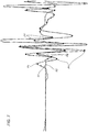
- the figure shows a monitoring system 100 for an environment having a more complex shape than those shown in Figures 1 and 2 .
- FIG. 3 shows three monitoring devices (1c, 1d, 1e), interconnected with each other.
- the devices 1c, 1d are fixed to vertical walls and the device 1e is fixed to an upper horizontal wall.
- the first device 1c detects the movement in a first authorised space 10A (edges 51) and in a second unauthorised space 9NA (edges 50).
- the second device 1d detects the movement in the spaces having as edges 52 and 53: the space with edges 52 is an unauthorised space 11NA, whilst the space with edges 53 is the authorised space 12A.
- a third device 1e detects the movement in the space having as edges 54 (circular area).
- the space having as edges 54 is an authorised space 13A and its purpose is such that the monitoring system considers certain spaces located inside unauthorised spaces (in the specific example, the space 13A is fully contained in the space 9NA and a portion of the same volume 13A is contained in the space 11NA) as authorised spaces.
- the situation described above is the one relative to a person who stops (that is, stops moving) in an unauthorised space and starts the movement again after a time greater than the duration of the time-out (after which, the algorithm has set the status variable as "unoccupied").
- the configuration described above, in which authorised spaces 13A are created inside unauthorised spaces 11A, allows the above-mentioned problem to be resolved.
- the control unit of the monitoring system 100 uses the signals of the various devices and keeps synchronised the detection devices so as to provide the correct time sequence of the events transmitted by the devices, to activate or not the alarm.
- the device 1 in the case of buildings but more in general for any type of zone monitored, can be kept active also in the presence of persons in the zone subject to monitoring: the operational logic of the device 1 allows authorised persons in the area to be distinguished from unauthorised persons, for which the alarm should be activated.
- the device 1, the system 100 and the monitoring method allow the problems highlighted with regard to prior art volumetric safety systems, which could have been kept active only if there were no persons present in the zone subject to monitoring, to be resolved.
- the invention described above is susceptible of industrial application and may be modified and adapted in several ways without thereby departing from the scope of the inventive concept. Moreover, all the details of the invention may be substituted for technically equivalent elements.
Landscapes
- Physics & Mathematics (AREA)
- General Physics & Mathematics (AREA)
- Alarm Systems (AREA)
- Burglar Alarm Systems (AREA)
Claims (11)
- Verfahren zum Überwachen eines vorgegebenen Raums (V), wobei der vorgegebene Raum (V) eine autorisierte Zone (3A) und eine nicht autorisierte Zone (2NA) umfasst, dadurch gekennzeichnet, dass es die folgenden Schritte umfasst:- a) Vorbereiten mindestens eines ersten volumetrischen Sensors (SV1) zum Detektieren eines ersten Bewegungssignals (S1), das für die Bewegung in der autorisierten Zone (3A) des Raums (V) repräsentativ ist;- b) Vorbereiten mindestens eines zweiten volumetrischen Sensors (SV2) zum Detektieren eines zweiten Bewegungssignals (S2), das für eine Bewegung in der nicht autorisierten Zone (2NA) des Raums (V) repräsentativ ist;- c) Verarbeiten des ersten Signals (S1) und des zweiten Signals (S2) zum Identifizieren einer Bewegung in dem Raum (V);- d1) Vorbereiten einer Statusvariablen, die einen ersten Wert einnehmen kann, der für die Anwesenheit von mindestens einer Person in dem Raum (V) indikativ ist, und einen zweiten Wert, der für die Abwesenheit von Personen in dem Raum (V) indikativ ist;- d2) Analysieren des ersten und zweiten Signals zum Detektieren einer Bewegung innerhalb der autorisierten Zone (3A) und der nicht autorisierten Zone (2NA) und Bewerten, ob die detektierte Bewegung in der autorisierten Zone (3A) oder in der nicht autorisierten Zone (2NA) detektiert wurde;d3) Befolgen der Identifizierung einer Bewegung:- e) Bereitstellen einer Alarmanzeige, wenn die Statusvariable den zweiten Wert aufweist und die Bewegung anfänglich in der nicht autorisierten Zone detektiert wurde; oder- f) wenn die Statusvariable den zweiten Wert aufweist und die Bewegung anfänglich in der autorisierten Zone detektiert wurde, Setzen der Statusvariablen auf den ersten Wert und Zurücksetzen und Aktivieren eines Countdowns der Zeit; oder- g) wenn die Statusvariable den ersten Wert aufweist, Zurücksetzen und Aktivieren des Countdowns der Zeit;- h) Setzen der Statusvariable auf den zweiten Wert, wenn der Countdown der Zeit abgelaufen ist, ohne dass eine weitere Bewegung detektiert wurde.
- Verfahren nach dem vorhergehenden Anspruch, wobei sich die autorisierte Zone zumindest teilweise mit der nicht autorisierten Zone überlappt und in dem Schritt e) eine Alarmanzeige verfügbar gemacht wird, wenn die Statusvariable den zweiten Wert aufweist und die Bewegung anfänglich nur in der nicht autorisierten Zone detektiert wurde.
- Verfahren nach einem der vorhergehenden Ansprüche, wobei es einen Initialisierungsschritt vor den Schritten von c) bis h) umfasst, in dem die Statusvariable gesetzt ist:- auf den ersten Wert, wenn eine Bewegung innerhalb des Raums (V) für eine vorgegebene Zeit detektiert wird;- auf den zweiten Wert, wenn innerhalb des vorgegebenen Raums (V) für eine vorbestimmte Zeit keine Bewegung detektiert wird.
- Verfahren nach einem der vorhergehenden Ansprüche, wobei die autorisierte Zone mindestens einen Abschnitt umfasst, der sich vollständig innerhalb der nicht autorisierten Zone befindet.
- Verfahren nach einem der vorhergehenden Ansprüche, wobei der Verarbeitungsschritt c) einen Schritt zum Analysieren der Spitzen der Signale (S1, S2) der Sensoren (SV1, SV2) zum Identifizieren einer Bewegung in dem Raum (V) umfasst.
- Verfahren nach einem der vorhergehenden Ansprüche, wobei der Verarbeitungsschritt einen Schritt zum Analysieren der Spitzen der Signale (S1, S2) der Sensoren (SV1, SV2) zum Identifizieren einer Bewegung in dem Raum (V) umfasst.
- Verfahren nach einem der vorhergehenden Ansprüche, wobei der Raum (V) eine Umgebung innerhalb eines Gebäudes liegt und die nicht autorisierte Zone (2NA) so positioniert ist, dass sie Öffnungen in Kommunikation mit der Außenseite der Umgebung umfasst.
- Vorrichtung (1) zum Überwachen eines vorgegebenen Raums (V) nach einem Verfahren nach einem der vorhergehenden Ansprüche,
dadurch gekennzeichnet, dass sie umfasst:- mindestens einen ersten volumetrischen Sensor (SV1) zum Detektieren eines ersten Bewegungssignals (S1), das für die Bewegung in einer autorisierten Zone (3A) des Raums (V) repräsentativ ist;- mindestens einen zweiten volumetrischen Sensor (SV2) zum Detektieren eines zweiten Bewegungssignals (S2), das für die Bewegung in einer nicht autorisierten Zone (2NA) des Raums (V) repräsentativ ist;- Verarbeitungsmittel, die zur Implementierung der Schritte c), d1), d2), d3), h) des Überwachungsverfahrens nach den vorhergehenden Ansprüchen ausgelegt sind. - Vorrichtung nach dem vorhergehenden Anspruch, wobei ein jeder der Sensoren (SV1, SV2) eine Spiegeloptik (01, 02) umfasst.
- Vorrichtung nach Anspruch 8 oder 9, wobei die Sensoren (SV1, SV2) und die Verarbeitungsmittel in den gleichen kastenförmigen Behälter (SC) integriert sind.
- System (100) zum Überwachen eines vorgegebenen Bereichs, dadurch gekennzeichnet, dass es umfasst:- eine Vielzahl an Vorrichtungen (1) nach einem der Ansprüche von 8 bis 10;- und eine Steuereinheit, die an eines jeden Gerät (1) angeschlossen ist, um die Alarmanzeige zu empfangen, und ausgelegt ist, um einen Alarm in Abhängigkeit von den Werten der Alarmanzeigen zu aktivieren;- Alarmmittel, die von der Steuereinheit aktiviert werden können.
Applications Claiming Priority (2)
| Application Number | Priority Date | Filing Date | Title |
|---|---|---|---|
| IT000299A ITBO20120299A1 (it) | 2012-05-31 | 2012-05-31 | Dispositivo, sistema e metodo di sorveglianza di un prestabilito volume. |
| PCT/IB2013/054360 WO2013179201A1 (en) | 2012-05-31 | 2013-05-27 | Device, system and method for monitoring a predetermined space |
Publications (2)
| Publication Number | Publication Date |
|---|---|
| EP2856446A1 EP2856446A1 (de) | 2015-04-08 |
| EP2856446B1 true EP2856446B1 (de) | 2020-11-11 |
Family
ID=46582776
Family Applications (1)
| Application Number | Title | Priority Date | Filing Date |
|---|---|---|---|
| EP13737394.0A Not-in-force EP2856446B1 (de) | 2012-05-31 | 2013-05-27 | Vorrichtung, system und verfahren zum überwachen eines vorgegebenen raums |
Country Status (4)
| Country | Link |
|---|---|
| US (1) | US9881469B2 (de) |
| EP (1) | EP2856446B1 (de) |
| IT (1) | ITBO20120299A1 (de) |
| WO (1) | WO2013179201A1 (de) |
Families Citing this family (4)
| Publication number | Priority date | Publication date | Assignee | Title |
|---|---|---|---|---|
| WO2016046780A1 (en) * | 2014-09-25 | 2016-03-31 | Micheli, Cesare | Surveillance method, device and system |
| EP3065113B1 (de) * | 2015-03-05 | 2020-06-10 | Gigaset Communications GmbH | Überwachungssystem |
| FR3055455B1 (fr) * | 2016-09-01 | 2019-01-25 | Freebox | Equipement autonome de surveillance de zone par capteur infrarouge passif multizone |
| DE102020210572A1 (de) * | 2020-08-20 | 2022-02-24 | Diehl Aerospace Gmbh | Kabine für ein Flugzeug mit einer Überwachungsanordnung, Flugzeug mit der Kabine, Überwachungsanordnung und Verfahren zur Überwachung einer Kabine eines Flugzeugs |
Family Cites Families (12)
| Publication number | Priority date | Publication date | Assignee | Title |
|---|---|---|---|---|
| WO2006093527A2 (en) * | 2004-07-30 | 2006-09-08 | U.S. Global Nanospace, Inc. | Modular autonomous perimeter security and non-lethal defense system |
| US7327253B2 (en) * | 2005-05-04 | 2008-02-05 | Squire Communications Inc. | Intruder detection and warning system |
| US7868812B2 (en) * | 2005-08-12 | 2011-01-11 | Patriot Technologies, Llp | Surveillance and warning system |
| US9036902B2 (en) * | 2007-01-29 | 2015-05-19 | Intellivision Technologies Corporation | Detector for chemical, biological and/or radiological attacks |
| FR2911987B1 (fr) * | 2007-01-29 | 2010-08-13 | Airbus France | Procede de surveillance de personnes autorisees et non autorisees dans un perimetre de securite autour d'un appareil |
| CA2634261A1 (en) * | 2007-06-08 | 2008-12-08 | International Ram Associates | Remote area monitoring system |
| US9215781B2 (en) * | 2008-04-16 | 2015-12-15 | Avo Usa Holding 2 Corporation | Energy savings and improved security through intelligent lighting systems |
| WO2011005074A1 (en) * | 2009-07-07 | 2011-01-13 | Mimos Berhad | Surveillance system and method |
| GB2489218A (en) * | 2011-03-17 | 2012-09-26 | Univ Strathclyde | Occupancy detection system |
| EP2729915B1 (de) * | 2011-07-05 | 2017-12-27 | Omron Corporation | Verfahren und vorrichtung zur projektiven volumenüberwachung |
| US9183686B2 (en) * | 2011-07-12 | 2015-11-10 | Tyco Fire & Security Gmbh | Method and system for people counting using passive infrared detectors |
| US8909382B1 (en) * | 2011-11-10 | 2014-12-09 | Universal Lighting Technologies, Inc. | Occupancy detection system and method having automatic adaptation capabilities |
-
2012
- 2012-05-31 IT IT000299A patent/ITBO20120299A1/it unknown
-
2013
- 2013-05-27 EP EP13737394.0A patent/EP2856446B1/de not_active Not-in-force
- 2013-05-27 US US14/404,305 patent/US9881469B2/en not_active Expired - Fee Related
- 2013-05-27 WO PCT/IB2013/054360 patent/WO2013179201A1/en not_active Ceased
Non-Patent Citations (1)
| Title |
|---|
| None * |
Also Published As
| Publication number | Publication date |
|---|---|
| US20150187191A1 (en) | 2015-07-02 |
| US9881469B2 (en) | 2018-01-30 |
| WO2013179201A1 (en) | 2013-12-05 |
| ITBO20120299A1 (it) | 2013-12-01 |
| EP2856446A1 (de) | 2015-04-08 |
Similar Documents
| Publication | Publication Date | Title |
|---|---|---|
| EP3118826B1 (de) | Heim-, bürosicherheitsüberwachungssystem unter verwendung von mobilen mikrodrohnen und ip-kameras | |
| JP7052583B2 (ja) | 監視システム | |
| US9251692B2 (en) | GPS directed intrusion system with data acquisition | |
| US9582975B2 (en) | Alarm routing in integrated security system based on security guards real-time location information in the premises for faster alarm response | |
| KR101381924B1 (ko) | 카메라 감시 장치를 이용한 보안 감시 시스템 및 방법 | |
| EP3418990A1 (de) | System und verfahren zur verbesserung der privatsphäre von häusern und anderen gebäuden mit einem angeschlossenen haussicherheits-/kontrollsystem, die unbemannten luftfahrzeugen ausgesetzt sind | |
| EP2856446B1 (de) | Vorrichtung, system und verfahren zum überwachen eines vorgegebenen raums | |
| JP4866801B2 (ja) | 集合住宅インターホンシステム | |
| KR20160006426A (ko) | 군사용 경계초소의 주둔지 방호 시스템 | |
| US9847016B2 (en) | System and method of communicating data from an alarm system to emergency services personnel | |
| KR200188880Y1 (ko) | 영상 전송용 보안 시스템 | |
| KR101042368B1 (ko) | 경비 시스템 및 그 제어 방법 | |
| KR101729485B1 (ko) | 레이더 센서를 이용한 창문 감시장치 | |
| KR101594053B1 (ko) | 융복합 솔루션을 통한 보안 시스템 | |
| EP2698773A1 (de) | Einbruchmeldeanlage und Verfahren zur Scharfschaltung einer Einbruchmeldeanlage | |
| JP6141058B2 (ja) | 警備システム | |
| RU186842U1 (ru) | Охранный робот | |
| KR101741312B1 (ko) | 가정용 실시간 감시시스템 | |
| JP2005216095A (ja) | 監視装置 | |
| KR102221825B1 (ko) | 출입 공간 모니터링 시스템 | |
| CN107123231A (zh) | 一种基于物联网的住宅区安防系统 | |
| KR20230129636A (ko) | 군사용 경계초소의 주둔지 방호 방법 | |
| JP2012036710A (ja) | 自動ドアの防犯装置 | |
| KR20130003918U (ko) | 의사 경보장치 | |
| KR20100087919A (ko) | 감시 시스템 및 그 제어 방법 |
Legal Events
| Date | Code | Title | Description |
|---|---|---|---|
| PUAI | Public reference made under article 153(3) epc to a published international application that has entered the european phase |
Free format text: ORIGINAL CODE: 0009012 |
|
| 17P | Request for examination filed |
Effective date: 20141223 |
|
| AK | Designated contracting states |
Kind code of ref document: A1 Designated state(s): AL AT BE BG CH CY CZ DE DK EE ES FI FR GB GR HR HU IE IS IT LI LT LU LV MC MK MT NL NO PL PT RO RS SE SI SK SM TR |
|
| AX | Request for extension of the european patent |
Extension state: BA ME |
|
| DAX | Request for extension of the european patent (deleted) | ||
| STAA | Information on the status of an ep patent application or granted ep patent |
Free format text: STATUS: EXAMINATION IS IN PROGRESS |
|
| 17Q | First examination report despatched |
Effective date: 20180927 |
|
| GRAP | Despatch of communication of intention to grant a patent |
Free format text: ORIGINAL CODE: EPIDOSNIGR1 |
|
| STAA | Information on the status of an ep patent application or granted ep patent |
Free format text: STATUS: GRANT OF PATENT IS INTENDED |
|
| INTG | Intention to grant announced |
Effective date: 20200707 |
|
| GRAS | Grant fee paid |
Free format text: ORIGINAL CODE: EPIDOSNIGR3 |
|
| GRAA | (expected) grant |
Free format text: ORIGINAL CODE: 0009210 |
|
| STAA | Information on the status of an ep patent application or granted ep patent |
Free format text: STATUS: THE PATENT HAS BEEN GRANTED |
|
| AK | Designated contracting states |
Kind code of ref document: B1 Designated state(s): AL AT BE BG CH CY CZ DE DK EE ES FI FR GB GR HR HU IE IS IT LI LT LU LV MC MK MT NL NO PL PT RO RS SE SI SK SM TR |
|
| REG | Reference to a national code |
Ref country code: GB Ref legal event code: FG4D |
|
| REG | Reference to a national code |
Ref country code: CH Ref legal event code: EP |
|
| REG | Reference to a national code |
Ref country code: AT Ref legal event code: REF Ref document number: 1334217 Country of ref document: AT Kind code of ref document: T Effective date: 20201115 |
|
| REG | Reference to a national code |
Ref country code: DE Ref legal event code: R096 Ref document number: 602013073972 Country of ref document: DE |
|
| REG | Reference to a national code |
Ref country code: IE Ref legal event code: FG4D |
|
| REG | Reference to a national code |
Ref country code: NL Ref legal event code: MP Effective date: 20201111 |
|
| REG | Reference to a national code |
Ref country code: AT Ref legal event code: MK05 Ref document number: 1334217 Country of ref document: AT Kind code of ref document: T Effective date: 20201111 |
|
| PG25 | Lapsed in a contracting state [announced via postgrant information from national office to epo] |
Ref country code: PT Free format text: LAPSE BECAUSE OF FAILURE TO SUBMIT A TRANSLATION OF THE DESCRIPTION OR TO PAY THE FEE WITHIN THE PRESCRIBED TIME-LIMIT Effective date: 20210311 Ref country code: NO Free format text: LAPSE BECAUSE OF FAILURE TO SUBMIT A TRANSLATION OF THE DESCRIPTION OR TO PAY THE FEE WITHIN THE PRESCRIBED TIME-LIMIT Effective date: 20210211 Ref country code: RS Free format text: LAPSE BECAUSE OF FAILURE TO SUBMIT A TRANSLATION OF THE DESCRIPTION OR TO PAY THE FEE WITHIN THE PRESCRIBED TIME-LIMIT Effective date: 20201111 Ref country code: FI Free format text: LAPSE BECAUSE OF FAILURE TO SUBMIT A TRANSLATION OF THE DESCRIPTION OR TO PAY THE FEE WITHIN THE PRESCRIBED TIME-LIMIT Effective date: 20201111 Ref country code: GR Free format text: LAPSE BECAUSE OF FAILURE TO SUBMIT A TRANSLATION OF THE DESCRIPTION OR TO PAY THE FEE WITHIN THE PRESCRIBED TIME-LIMIT Effective date: 20210212 |
|
| PG25 | Lapsed in a contracting state [announced via postgrant information from national office to epo] |
Ref country code: SE Free format text: LAPSE BECAUSE OF FAILURE TO SUBMIT A TRANSLATION OF THE DESCRIPTION OR TO PAY THE FEE WITHIN THE PRESCRIBED TIME-LIMIT Effective date: 20201111 Ref country code: PL Free format text: LAPSE BECAUSE OF FAILURE TO SUBMIT A TRANSLATION OF THE DESCRIPTION OR TO PAY THE FEE WITHIN THE PRESCRIBED TIME-LIMIT Effective date: 20201111 Ref country code: LV Free format text: LAPSE BECAUSE OF FAILURE TO SUBMIT A TRANSLATION OF THE DESCRIPTION OR TO PAY THE FEE WITHIN THE PRESCRIBED TIME-LIMIT Effective date: 20201111 Ref country code: IS Free format text: LAPSE BECAUSE OF FAILURE TO SUBMIT A TRANSLATION OF THE DESCRIPTION OR TO PAY THE FEE WITHIN THE PRESCRIBED TIME-LIMIT Effective date: 20210311 Ref country code: BG Free format text: LAPSE BECAUSE OF FAILURE TO SUBMIT A TRANSLATION OF THE DESCRIPTION OR TO PAY THE FEE WITHIN THE PRESCRIBED TIME-LIMIT Effective date: 20210211 Ref country code: AT Free format text: LAPSE BECAUSE OF FAILURE TO SUBMIT A TRANSLATION OF THE DESCRIPTION OR TO PAY THE FEE WITHIN THE PRESCRIBED TIME-LIMIT Effective date: 20201111 |
|
| REG | Reference to a national code |
Ref country code: LT Ref legal event code: MG9D |
|
| PG25 | Lapsed in a contracting state [announced via postgrant information from national office to epo] |
Ref country code: HR Free format text: LAPSE BECAUSE OF FAILURE TO SUBMIT A TRANSLATION OF THE DESCRIPTION OR TO PAY THE FEE WITHIN THE PRESCRIBED TIME-LIMIT Effective date: 20201111 |
|
| PG25 | Lapsed in a contracting state [announced via postgrant information from national office to epo] |
Ref country code: LT Free format text: LAPSE BECAUSE OF FAILURE TO SUBMIT A TRANSLATION OF THE DESCRIPTION OR TO PAY THE FEE WITHIN THE PRESCRIBED TIME-LIMIT Effective date: 20201111 Ref country code: SK Free format text: LAPSE BECAUSE OF FAILURE TO SUBMIT A TRANSLATION OF THE DESCRIPTION OR TO PAY THE FEE WITHIN THE PRESCRIBED TIME-LIMIT Effective date: 20201111 Ref country code: RO Free format text: LAPSE BECAUSE OF FAILURE TO SUBMIT A TRANSLATION OF THE DESCRIPTION OR TO PAY THE FEE WITHIN THE PRESCRIBED TIME-LIMIT Effective date: 20201111 Ref country code: EE Free format text: LAPSE BECAUSE OF FAILURE TO SUBMIT A TRANSLATION OF THE DESCRIPTION OR TO PAY THE FEE WITHIN THE PRESCRIBED TIME-LIMIT Effective date: 20201111 Ref country code: CZ Free format text: LAPSE BECAUSE OF FAILURE TO SUBMIT A TRANSLATION OF THE DESCRIPTION OR TO PAY THE FEE WITHIN THE PRESCRIBED TIME-LIMIT Effective date: 20201111 Ref country code: SM Free format text: LAPSE BECAUSE OF FAILURE TO SUBMIT A TRANSLATION OF THE DESCRIPTION OR TO PAY THE FEE WITHIN THE PRESCRIBED TIME-LIMIT Effective date: 20201111 |
|
| REG | Reference to a national code |
Ref country code: DE Ref legal event code: R097 Ref document number: 602013073972 Country of ref document: DE |
|
| PG25 | Lapsed in a contracting state [announced via postgrant information from national office to epo] |
Ref country code: DK Free format text: LAPSE BECAUSE OF FAILURE TO SUBMIT A TRANSLATION OF THE DESCRIPTION OR TO PAY THE FEE WITHIN THE PRESCRIBED TIME-LIMIT Effective date: 20201111 |
|
| PLBE | No opposition filed within time limit |
Free format text: ORIGINAL CODE: 0009261 |
|
| STAA | Information on the status of an ep patent application or granted ep patent |
Free format text: STATUS: NO OPPOSITION FILED WITHIN TIME LIMIT |
|
| 26N | No opposition filed |
Effective date: 20210812 |
|
| PG25 | Lapsed in a contracting state [announced via postgrant information from national office to epo] |
Ref country code: NL Free format text: LAPSE BECAUSE OF FAILURE TO SUBMIT A TRANSLATION OF THE DESCRIPTION OR TO PAY THE FEE WITHIN THE PRESCRIBED TIME-LIMIT Effective date: 20201111 Ref country code: AL Free format text: LAPSE BECAUSE OF FAILURE TO SUBMIT A TRANSLATION OF THE DESCRIPTION OR TO PAY THE FEE WITHIN THE PRESCRIBED TIME-LIMIT Effective date: 20201111 |
|
| PG25 | Lapsed in a contracting state [announced via postgrant information from national office to epo] |
Ref country code: ES Free format text: LAPSE BECAUSE OF FAILURE TO SUBMIT A TRANSLATION OF THE DESCRIPTION OR TO PAY THE FEE WITHIN THE PRESCRIBED TIME-LIMIT Effective date: 20201111 Ref country code: SI Free format text: LAPSE BECAUSE OF FAILURE TO SUBMIT A TRANSLATION OF THE DESCRIPTION OR TO PAY THE FEE WITHIN THE PRESCRIBED TIME-LIMIT Effective date: 20201111 |
|
| REG | Reference to a national code |
Ref country code: CH Ref legal event code: PL |
|
| PG25 | Lapsed in a contracting state [announced via postgrant information from national office to epo] |
Ref country code: CH Free format text: LAPSE BECAUSE OF NON-PAYMENT OF DUE FEES Effective date: 20210531 Ref country code: MC Free format text: LAPSE BECAUSE OF FAILURE TO SUBMIT A TRANSLATION OF THE DESCRIPTION OR TO PAY THE FEE WITHIN THE PRESCRIBED TIME-LIMIT Effective date: 20201111 Ref country code: LI Free format text: LAPSE BECAUSE OF NON-PAYMENT OF DUE FEES Effective date: 20210531 Ref country code: LU Free format text: LAPSE BECAUSE OF NON-PAYMENT OF DUE FEES Effective date: 20210527 |
|
| REG | Reference to a national code |
Ref country code: BE Ref legal event code: MM Effective date: 20210531 |
|
| PG25 | Lapsed in a contracting state [announced via postgrant information from national office to epo] |
Ref country code: IE Free format text: LAPSE BECAUSE OF NON-PAYMENT OF DUE FEES Effective date: 20210527 |
|
| PG25 | Lapsed in a contracting state [announced via postgrant information from national office to epo] |
Ref country code: IS Free format text: LAPSE BECAUSE OF FAILURE TO SUBMIT A TRANSLATION OF THE DESCRIPTION OR TO PAY THE FEE WITHIN THE PRESCRIBED TIME-LIMIT Effective date: 20210311 |
|
| PG25 | Lapsed in a contracting state [announced via postgrant information from national office to epo] |
Ref country code: BE Free format text: LAPSE BECAUSE OF NON-PAYMENT OF DUE FEES Effective date: 20210531 |
|
| PG25 | Lapsed in a contracting state [announced via postgrant information from national office to epo] |
Ref country code: HU Free format text: LAPSE BECAUSE OF FAILURE TO SUBMIT A TRANSLATION OF THE DESCRIPTION OR TO PAY THE FEE WITHIN THE PRESCRIBED TIME-LIMIT; INVALID AB INITIO Effective date: 20130527 |
|
| PG25 | Lapsed in a contracting state [announced via postgrant information from national office to epo] |
Ref country code: CY Free format text: LAPSE BECAUSE OF FAILURE TO SUBMIT A TRANSLATION OF THE DESCRIPTION OR TO PAY THE FEE WITHIN THE PRESCRIBED TIME-LIMIT Effective date: 20201111 |
|
| PG25 | Lapsed in a contracting state [announced via postgrant information from national office to epo] |
Ref country code: MK Free format text: LAPSE BECAUSE OF FAILURE TO SUBMIT A TRANSLATION OF THE DESCRIPTION OR TO PAY THE FEE WITHIN THE PRESCRIBED TIME-LIMIT Effective date: 20201111 |
|
| PGFP | Annual fee paid to national office [announced via postgrant information from national office to epo] |
Ref country code: GB Payment date: 20240529 Year of fee payment: 12 |
|
| PGFP | Annual fee paid to national office [announced via postgrant information from national office to epo] |
Ref country code: DE Payment date: 20240529 Year of fee payment: 12 |
|
| PGFP | Annual fee paid to national office [announced via postgrant information from national office to epo] |
Ref country code: FR Payment date: 20240529 Year of fee payment: 12 |
|
| PG25 | Lapsed in a contracting state [announced via postgrant information from national office to epo] |
Ref country code: MT Free format text: LAPSE BECAUSE OF FAILURE TO SUBMIT A TRANSLATION OF THE DESCRIPTION OR TO PAY THE FEE WITHIN THE PRESCRIBED TIME-LIMIT Effective date: 20201111 |
|
| PGFP | Annual fee paid to national office [announced via postgrant information from national office to epo] |
Ref country code: IT Payment date: 20240530 Year of fee payment: 12 |
|
| REG | Reference to a national code |
Ref country code: DE Ref legal event code: R119 Ref document number: 602013073972 Country of ref document: DE |
|
| PG25 | Lapsed in a contracting state [announced via postgrant information from national office to epo] |
Ref country code: TR Free format text: LAPSE BECAUSE OF FAILURE TO SUBMIT A TRANSLATION OF THE DESCRIPTION OR TO PAY THE FEE WITHIN THE PRESCRIBED TIME-LIMIT Effective date: 20201111 |
|
| GBPC | Gb: european patent ceased through non-payment of renewal fee |
Effective date: 20250527 |
|
| PG25 | Lapsed in a contracting state [announced via postgrant information from national office to epo] |
Ref country code: GB Free format text: LAPSE BECAUSE OF NON-PAYMENT OF DUE FEES Effective date: 20250527 |
|
| PG25 | Lapsed in a contracting state [announced via postgrant information from national office to epo] |
Ref country code: DE Free format text: LAPSE BECAUSE OF NON-PAYMENT OF DUE FEES Effective date: 20251202 |
|
| PG25 | Lapsed in a contracting state [announced via postgrant information from national office to epo] |
Ref country code: IT Free format text: LAPSE BECAUSE OF NON-PAYMENT OF DUE FEES Effective date: 20250527 |
|
| PG25 | Lapsed in a contracting state [announced via postgrant information from national office to epo] |
Ref country code: FR Free format text: LAPSE BECAUSE OF NON-PAYMENT OF DUE FEES Effective date: 20250531 |