EP2856485B1 - Dispositif de commande, en particulier sous forme de commutateur électrique - Google Patents
Dispositif de commande, en particulier sous forme de commutateur électrique Download PDFInfo
- Publication number
- EP2856485B1 EP2856485B1 EP13728111.9A EP13728111A EP2856485B1 EP 2856485 B1 EP2856485 B1 EP 2856485B1 EP 13728111 A EP13728111 A EP 13728111A EP 2856485 B1 EP2856485 B1 EP 2856485B1
- Authority
- EP
- European Patent Office
- Prior art keywords
- operating device
- guide
- switching
- carrier
- shifting component
- Prior art date
- Legal status (The legal status is an assumption and is not a legal conclusion. Google has not performed a legal analysis and makes no representation as to the accuracy of the status listed.)
- Not-in-force
Links
- 238000006073 displacement reaction Methods 0.000 claims description 26
- 230000004888 barrier function Effects 0.000 claims description 7
- 230000007935 neutral effect Effects 0.000 claims description 6
- 230000007246 mechanism Effects 0.000 description 7
- 239000000969 carrier Substances 0.000 description 4
- 238000011161 development Methods 0.000 description 3
- 230000018109 developmental process Effects 0.000 description 3
- 239000000243 solution Substances 0.000 description 3
- 208000012886 Vertigo Diseases 0.000 description 1
- 230000001419 dependent effect Effects 0.000 description 1
- 239000000284 extract Substances 0.000 description 1
- 238000000034 method Methods 0.000 description 1
- 230000008569 process Effects 0.000 description 1
Images


Classifications
-
- H—ELECTRICITY
- H01—ELECTRIC ELEMENTS
- H01H—ELECTRIC SWITCHES; RELAYS; SELECTORS; EMERGENCY PROTECTIVE DEVICES
- H01H25/00—Switches with compound movement of handle or other operating part
- H01H25/002—Switches with compound movement of handle or other operating part having an operating member rectilinearly slidable in different directions
-
- H—ELECTRICITY
- H01—ELECTRIC ELEMENTS
- H01H—ELECTRIC SWITCHES; RELAYS; SELECTORS; EMERGENCY PROTECTIVE DEVICES
- H01H25/00—Switches with compound movement of handle or other operating part
- H01H25/008—Operating part movable both angularly and rectilinearly, the rectilinear movement being perpendicular to the axis of angular movement
-
- H—ELECTRICITY
- H01—ELECTRIC ELEMENTS
- H01H—ELECTRIC SWITCHES; RELAYS; SELECTORS; EMERGENCY PROTECTIVE DEVICES
- H01H25/00—Switches with compound movement of handle or other operating part
- H01H25/002—Switches with compound movement of handle or other operating part having an operating member rectilinearly slidable in different directions
- H01H2025/004—Switches with compound movement of handle or other operating part having an operating member rectilinearly slidable in different directions the operating member being depressable perpendicular to the other directions
Definitions
- the invention relates to an operating device according to the preamble of patent claim 1.
- Electric switches formed in the manner of a joystick and / or cursor switch serve as operating devices for inputting data for an electrical appliance by a user.
- switches are used for car radios, navigation devices, on-board computers or for controlling other functions in motor vehicles.
- an electrical switch can also be used as a multi-function switch for menu control of functions via a display in the motor vehicle.
- Such, from the EP 1 970 929 A1 known operating device has a movably mounted actuator.
- the actuating member cooperates with a displacement means in such a way that the actuating member is displaceable by the user in a displacement plane in at least one direction from a neutral position into a sliding position assigned to this direction.
- the sliding position is formed as a switching position, such that the actuating member in the switching position acts on a switching element for generating a switching signal switching.
- the displacement means comprises a sliding member, on which the actuating member is arranged and / or with which the actuating member is in operative connection, and a guide support.
- the sliding member is displaceably mounted on the guide carrier by means of a ball bearing. It has been found in such an operating device that the displacement means has a certain amount of play, so that it lacks precision in the sliding movement for the user.
- the guide carrier is arranged on an inner support. It is advisable for the sake of stability to arrange the guide carrier mounted on two opposite bearing points in the inner support.
- the guide carrier may be configured in the manner of a guide pin, a guide rod, a guide pin or the like.
- the sliding member is thus arranged in a compact manner on the inner support and displaceable in a first direction relative to the inner support.
- a ball bearing a linear ball guide is provided.
- the user is thus offered a precise and / or play-free operation of the operating device and it is also a reliable operation of the switch guaranteed. Further embodiments of the invention are the subject of the dependent claims.
- the actuating member may additionally be displaceable in a further displacement plane from the neutral position into a further sliding position.
- the displacement means comprise a further guide carrier.
- the inner support can in turn be mounted displaceably by means of a ball bearing on the other guide support, so that a precise and play-free adjustment is achieved in the further sliding position.
- the further guide carrier can be arranged on an outer support.
- the further guide carrier may be mounted on two opposite bearing points in the outer carrier.
- the arrangement of the guide carrier is such that the first and the second direction are substantially perpendicular to each other.
- the actuator in the manner of a wind rose can be moved by the user.
- the ball guide may comprise balls located in a ball cage, whereby a simple assembly of the ball bearing is given.
- the ball cage for the guide carrier can be arranged in a compact manner on the sliding member and / or the ball cage for the further guide carrier on the inner support.
- two guide carriers and two further guide carriers are each arranged parallel to one another.
- the invention provides a rotary and / or push and / or sliding plate with ball cages for storage and / or guidance in the horizontal direction.
- a rotating means may be provided for the actuator, so that the actuator is rotatable with respect to the sliding member.
- the actuator can rotate through the Users interact with a switching element to generate a switching signal.
- the rotating means comprises a ball bearing for rotatable mounting on the sliding member.
- a further displacement means for the actuator may be provided for a further extended functionality, such that the actuator is linearly movable by at least a distance from a zero position to an actuating position approximately perpendicular to the displacement plane with respect to the sliding member.
- the actuating position can in turn be designed as a switching element having a switching position for generating a switching signal, so that the actuator further allows a kind of "Enter" operation for the user.
- the further displacement means may comprise a guide member arranged displaceably on the sliding component.
- the ball bearing can be arranged for the rotating means on the guide part.
- the increased ergonomics for the user can be a leaf spring with the actuator and a gate on the guide part to produce a feel for the rotational movement in operative connection.
- the switching element for the generation of a switching signal wherein the switching signal is generated in particular in the respective switching position of the actuator from a light barrier, an electrical contact element in the manner of a Kurzhubtaste or a Wegmattendoms from a sensor o.
- the haptic for the sliding movement can be generated in a simple manner by means of a switching element in the manner of a short-stroke key or a switching mat dome.
- the haptic for the displacement movement can also be generated by means of a magnet system.
- a controllable feel by means of an electric motor, an electromagnet o. The like. Be provided.
- Fig. 1 is an operating device 1, which is designed as an electrical switch in the manner of a joystick and / or cursor switch to see.
- the switch 1 has a housing 2 from which an actuator 3 for operation by the user protrudes.
- the Actuator 3 is movably mounted in the housing 2. Namely, the actuator 3 by moving in accordance with the arrows 4 in south-north direction and the arrows 5 in the east-west direction in the manner of a wind rose actuated, as well as on the basis of Fig. 2 can be seen. Further, the actuator 3 can be operated by rotating according to the double arrow 6. Finally, the actuator 3 is still movable by pressing the arrow 7, as in Fig. 3 is shown.
- the switch 1 is used for example in the motor vehicle for operating a navigation system.
- the respective inputs for the navigation system can be made by the user by appropriate movement or actuation of the actuator 3.
- the control device 1 may have further located in the housing 2 actuators 21 for electrical switches for direct selection of various other functions.
- the representation of a specific menu for the navigation system can be selected on a screen in the motor vehicle.
- the actuator 3 cooperates with a displacement means 8 such that the actuating member 3 is displaceable in a displacement plane in at least one direction 4 from a neutral position into a sliding position.
- the sliding position is formed as a switching position, such that the actuating member 3 in the switching position on a switching element not further shown switching acting, so as to generate a corresponding switching signal for the shift position.
- the displacement means 8 comprises a sliding member 19 and a guide bracket 10.
- the sliding member 19, the actuator 3 is arranged.
- the actuating member 3 is in operative connection with the sliding component 19 via further components, in order to allow further functionalities in addition to the sliding movement.
- a further functionality may be the turning of the actuating member 3, as will be explained in more detail below.
- the sliding member 19 is displaceably mounted on the guide bracket 10 by means of a ball bearing 9.
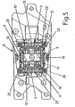
- the guide carrier 10 is arranged on an inner support 11, as shown in FIG Fig. 5 can be seen.
- the guide carrier 10 is mounted on two opposite bearing points 22 in the inner support 11.
- two guide carriers 10 are arranged parallel to one another on the inner support 11.
- the sliding member 19 is thus on the ball bearing 9 on the guide bracket 10 in a first direction 4, in the direction north-south, relative to the inner support 11 slidably.
- the displacement means 8 comprises a further guide support 10 ', as in FIG Fig. 4 you can see.
- the inner support 11 is slidably mounted by means of a ball bearing 9 on the other guide support 10 '.
- the further guide carrier 10 ' is in turn arranged on an outer carrier 12, the further guide carrier 10' is in turn mounted on two opposite bearing points 22 'in the outer carrier 12.
- the precise guide half are also two guide support 10 'arranged parallel to each other on the outer support 12.
- the inner support 11 is displaceable together with the sliding member 19 in a second direction 5, in the direction east-west, relative to the outer support 12, so that consequently the actuating member 3 is displaceable in a further displacement plane from the neutral position to a further sliding position ,
- the first direction 4 corresponding north-south and the second direction 5 corresponding east-west are substantially perpendicular to each other in the manner of a wind rose.
- the ball guide comprises according to Fig. 3 or Fig. 4
- the ball cage 23 for the guide carrier 10 is arranged on the sliding member 19 and the ball cage 23 for the further guide bracket 10 'on the inner support 11.
- a rotating means 13 is provided for the actuating member 3, such that the actuating member 3 with respect to the sliding member 19 is rotatable.
- the actuator 3 can be rotated by at least one angle from an initial position in at least one rotational position, wherein the rotational position is in turn formed as a switch element having a switching position.
- the actuator 3 is infinitely rotatable, wherein when turning the actuator 3 in Direction 6 corresponding signals are generated in the manner of switching signals of a rotary encoder.
- a photocell 24 is located, as in Fig. 3 can be seen, with the photocell 24 a rotatable means 13 located on the sprocket 26 cooperates.
- the rotating means 13 further comprises a ball bearing 14 for rotatable mounting on the sliding member 19th
- the actuator 3 is linearly movable by at least a distance from a zero position to an actuating position approximately perpendicular to the displacement plane with respect to the sliding member 19 by pressing in the direction 7.
- the actuating position is also formed as a switching element 27 having a switching position for generating a switching signal. This switching signal can be used, for example, as an enter signal.
- the further displacement means 15 comprises the guide member 18 which is displaceably arranged on the sliding component 19.
- the ball bearing 14 for the rotation means 13 is in turn arranged on the guide member 18.
- switching element 27 is actuated by cooperation with the sliding member 19.
- the switching element 27 is designed as a Kurzhubtaste and thus simultaneously causes the feel for the user.
- the switching element for the rotational movement consists, as already mentioned, of a light barrier 24.
- the switching elements for the sliding movement in east-west and south-north direction also consist of light barriers not shown.
- the switching elements for the generation of the switching signal in the switching position in any way from a photocell, an electrical contact element in the manner of a Kurzhubtaste or a Wegtendom, from a sensor o. The like. consist.
- the haptic for the sliding movement is generated by means of a switching element 16 in the manner of a Kurzhubtaste or a Heidelbergmattendoms, as in Fig. 6 you can see. If desired, however, the switching elements 16 can also be used for generating the switching signal for the displacement movement, so that it is possible to dispense with other switching elements.
- the feel for the sliding movement can also be generated by means of a magnet system 17, as in Fig. 7 can be seen closer.
- the Enter wave 19 is mounted on two parallel guide pins 10, 10 and two ball cages 23 in the inner support 11, as the Fig. 5 can be seen.
- This storage system results in a play-free but also very low-friction storage of the sliding mechanism.
- the escape shaft 19 shifts over the guide pins 10, 10, in this case for the north or south direction, and triggers the switching signal via a light barrier system. So that a collision-free movement is given, the take-off shaft 19 has Fig. 6 sufficient clearance 30 through corresponding recesses on the inner support 11 and rests exclusively on the switching elements 16.
- the haptic is generated via a switching element 16, in this case via a switching mat dome or a short-stroke key, as in FIG Fig. 6 you can see.
- the switching element 16 is pressed and forms the feel for the sliding movement.
- a magnet system 17 can be used for Haptikerzeugung, which in Fig. 7 is shown.
- the switching element 16 for this sliding direction is according to Fig. 4 and 6 stored in the inner support 11 and is actuated via the discharge shaft 19.
- the guide pins 10 in the inner support 11, on which the shooter shaft 19 is mounted via the ball cages 23, are used (for this direction, the guide pins 10 are fixedly mounted in the discharge shaft 19). that transmit force to the inner support 11, as you can see from Fig. 3 .
- Fig. 4 and Fig. 5 sees.
- the entire push-turn-slide unit shifts in the east or west direction (see also Fig. 6 ).
- the inner support 11 is also mounted on two parallel guide pins 10 'and ball cages 23 in the outer support 12 and this in turn in the base 20.
- the inner support 11 shifts due to the fixed in east-west direction storage of the guide pins 10 in the return shaft 19 on the guide pins 10 ', so that the entire push-turn sliding Unit is moved in east or west direction (see also Fig. 6 ).
- the signal is also detected by a light barrier system.
- the haptic is also generated here by means of a switching element 16, in this case a switching mat or a Kurzhubtaster stored in the base 20, as based on Fig. 3 or Fig. 6 can be seen.
- a switching element 16 in this case a switching mat or a Kurzhubtaster stored in the base 20, as based on Fig. 3 or Fig. 6 can be seen.
- To ensure a collision-free function is according to Fig. 6 for the movable push-turn-slide unit including inner support 11 in the base 20 sufficient clearance 30 'is provided.
- the inner support 11 rests exclusively on the switching elements 16, as based on the Fig. 6 can be seen.
- the rotatable unit and the unit that fulfills the push function are seated accordingly Fig. 3 and Fig. 4 on the take-off shaft 19, whereby they are decoupled from the sliding mechanism.
- the rotary and the push mechanism make the sliding movement with.
- the switching and the haptic generation of the push mechanism are realized via a Kurzhubtaster 27 connected to a circuit board 25 in the knob 3, as the Fig. 3 and the Fig. 4 can be removed.
- the switching signal for the rotating unit is according to Fig. 3 generated by means of a light barrier 24 on the circuit board 25 in the knob 3.
- the haptic generation of the rotating unit is according to Fig. 3 and Fig. 4 via a leaf spring 28, connected to the pivot bearing 13, and a trained on the guide member 18 link 29 generated.
- Such a multi-function switch can be used for car radios, for navigation systems and / or for control devices, displays o. The like. In motor vehicles.
- the invention is not limited to the described and illustrated embodiment. Rather, it also encompasses all expert developments within the scope of the invention defined by the claims.
- such a multi-function switch can also be advantageously used as input means for computers, machine tools, household appliances or the like.
- the invention can be used not only in the multi-function switches described but also in such switches, in which the actuating member is configured only displaceable.
Landscapes
- Switches With Compound Operations (AREA)
Claims (13)
- Dispositif de commande, en particulier commutateur électrique sous la forme d'un interrupteur à levier manche à balai et/ou un commutateur curseur, comprenant un organe d'actionnement mobile (3), l'organe d'actionnement (3) coopérant avec un moyen de coulissement (8) de telle sorte que l'organe d'actionnement (3) puisse se coulisser dans un plan de coulissement dans au moins une direction (4, 5) à partir d'une position neutre dans une position de coulissement, la position de coulissement étant conçue sous la forme d'une position de commutation de telle sorte que l'organe d'actionnement (3) dans la position de commutation agisse par commutation sur un élément de commutation pour produire un signal de commutation, le moyen de coulissement (8) comprend un élément coulissant (19) sur lequel l'organe d'actionnement (3) est disposé et/ou avec lequel l'organe d'actionnement (3) est en liaison active, et un support de guidage (10) et l'élément coulissant (19) est monté coulissant au moyen d'un roulement à billes (9) sur le support de guidage (10), caractérisé en ce que le support de guidage (10) est monté sur deux points d'appui (22) se faisant face l'un l'autre sur un support intérieur (11) de telle sorte que l'élément coulissant (19) puisse être coulissé dans une première direction (4) par rapport au support intérieur (11) et en ce que le roulement à billes (9) est un guidage à billes linéaire.
- Dispositif de commande selon la revendication 1, caractérisé en ce que l'organe d'actionnement (3) peut être coulissé dans un autre plan de coulissement à partir de la position neutre dans une autre position de coulissement, et en ce que le moyen de coulissement (8) comprend un autre support de guidage (10'), le support intérieur (11) étant monté coulissant au moyen d'un roulement à billes (9) sur l'autre support de guidage (10').
- Dispositif de commande selon la revendication 1 ou 2, caractérisé en ce que l'autre support de guidage (10') est monté sur deux points d'appui (22') se faisant face l'un l'autre sur un support extérieur (12) de telle sorte que le support interne (11) puisse être coulissé conjointement avec l'élément coulissant (19) dans une seconde direction (5) par rapport au support extérieur (12).
- Dispositif de commande selon la revendication 3, caractérisé en ce que la première ainsi que la seconde direction (4, 5) sont sensiblement perpendiculaires l'une par rapport à l'autre.
- Dispositif de commande selon l'une des revendications 1 à 4, caractérisé en ce que le roulement à billes comprend des billes (9) se trouvant dans une cage à billes (23), en ce que la cage à billes (23) pour le support de guidage (10) est disposée sur l'élément coulissant (19), et en ce que la cage à billes (23) pour l'autre support de guidage (10') est disposée sur le support intérieur (11).
- Dispositif de commande selon l'une des revendications 1 à 5, caractérisé en ce qu'il est prévu un moyen rotatif (13) pour l'organe d'actionnement (3) de telle sorte que l'organe d'actionnement (3) soit rotatif par rapport à l'élément coulissant (19) et en ce que l'organe d'actionnement (3) coopère lors de la rotation avec un élément de commutation (24) pour produire un signal de commutation.
- Dispositif de commande selon la revendication 6, caractérisé en ce que le moyen de rotation (13) comprend un roulement à billes (14) pour être monté en rotation sur l'élément coulissant (19).
- Dispositif de commande selon l'une des revendications 1 à 7, caractérisé en ce qu'il est prévu un autre moyen de coulissement (15) pour l'organe d'actionnement (3) de telle sorte que l'organe d'actionnement (3) puisse se déplacer linéairement par rapport à l'élément coulissant (19) sensiblement perpendiculairement par rapport au niveau de coulissement d'au moins un trajet à partir d'une position nulle dans une position d'actionnement et en ce que la position d'actionnement est conçue sous la forme d'une position de commutation présentant un élément de commutation (27) pour produire un signal de commutation.
- Dispositif de commande selon l'une des revendications 1 à 8, caractérisé en ce que l'autre moyen de coulissement (15) comprend une partie de guidage (18) disposée coulissant sur l'élément coulissant (19).
- Dispositif de commande selon la revendication 9, caractérisé en ce que le roulement à billes (14) pour le moyen rotatif (13) est disposé sur la partie de guidage (18).
- Dispositif de commande selon la revendication 9 ou 10, caractérisé en ce qu'un ressort à lames (28) est en liaison active avec l'organe d'actionnement (3) ainsi qu'avec une coulisse (29) sur une partie de guidage (18) pour produire une haptique pour le mouvement de rotation.
- Dispositif de commande selon l'une des revendications 1 à 11, caractérisé en ce que l'élément de commutation pour la production d'un signal de commutation est constitué d'une barrière lumineuse (24), d'un élément de contact électrique, d'une touche à faible course (27), d'un dôme de tapis sensible ou d'un capteur.
- Dispositif de commande selon l'une des revendications 1 à 12, caractérisé en ce que l'haptique pour le mouvement de coulissement est produit au moyen d'un élément de commutation (16), d'une touche à faible course, d'un dôme de tapis sensible ou d'un système d'aimant (17).
Applications Claiming Priority (2)
| Application Number | Priority Date | Filing Date | Title |
|---|---|---|---|
| DE102012010591 | 2012-05-30 | ||
| PCT/EP2013/001583 WO2013178357A1 (fr) | 2012-05-30 | 2013-05-29 | Dispositif de commande, en particulier sous forme de commutateur électrique |
Publications (2)
| Publication Number | Publication Date |
|---|---|
| EP2856485A1 EP2856485A1 (fr) | 2015-04-08 |
| EP2856485B1 true EP2856485B1 (fr) | 2018-04-11 |
Family
ID=48607200
Family Applications (1)
| Application Number | Title | Priority Date | Filing Date |
|---|---|---|---|
| EP13728111.9A Not-in-force EP2856485B1 (fr) | 2012-05-30 | 2013-05-29 | Dispositif de commande, en particulier sous forme de commutateur électrique |
Country Status (4)
| Country | Link |
|---|---|
| EP (1) | EP2856485B1 (fr) |
| DE (1) | DE102013008972A1 (fr) |
| ES (1) | ES2675276T3 (fr) |
| WO (1) | WO2013178357A1 (fr) |
Families Citing this family (6)
| Publication number | Priority date | Publication date | Assignee | Title |
|---|---|---|---|---|
| DE102015107992B4 (de) * | 2015-05-20 | 2017-11-02 | Preh Gmbh | Bedienelement mit Drehsteller- und Verschiebefunktionalität |
| US11397108B2 (en) | 2015-06-16 | 2022-07-26 | Marquardt Gmbh | Multi-function controller and method of using same |
| DE102015015511B4 (de) | 2015-11-30 | 2022-03-24 | Audi Ag | Bedienvorrichtung für ein Kraftfahrzeug und Verfahren zum Betreiben einer Bedienvorrichtung |
| US10527462B2 (en) | 2016-07-08 | 2020-01-07 | Marquardt Gmbh | Encoder and method of using the same |
| DE102019214109A1 (de) * | 2019-09-17 | 2021-03-18 | Zf Friedrichshafen Ag | Bedienvorrichtung, insbesondere für eine Vorrichtung eines Kraftfahrzeugs |
| CN110828221B (zh) * | 2019-12-12 | 2025-06-24 | 东莞市林积为科技股份有限公司 | 一种旋转换挡的旋钮开关 |
Family Cites Families (3)
| Publication number | Priority date | Publication date | Assignee | Title |
|---|---|---|---|---|
| BE1015905A6 (fr) * | 2004-02-13 | 2005-11-08 | Prud Homme Francois | Touche multi-directions munie d'une queue mobile s'engrenant tour a tour dans quatre ouvertures pour decrire de memoire vingt-huit trajets sensitifs detectes. |
| EP1750195B1 (fr) * | 2005-08-05 | 2011-01-19 | Niles Co., Ltd. | Dispositif d'entrée de manette de commande |
| FR2913811B1 (fr) * | 2007-03-12 | 2009-05-08 | Itt Mfg Enterprises Inc | Organe de commande multidirectionnel ergonomique |
-
2013
- 2013-05-28 DE DE102013008972A patent/DE102013008972A1/de not_active Withdrawn
- 2013-05-29 EP EP13728111.9A patent/EP2856485B1/fr not_active Not-in-force
- 2013-05-29 WO PCT/EP2013/001583 patent/WO2013178357A1/fr not_active Ceased
- 2013-05-29 ES ES13728111.9T patent/ES2675276T3/es active Active
Also Published As
| Publication number | Publication date |
|---|---|
| EP2856485A1 (fr) | 2015-04-08 |
| ES2675276T3 (es) | 2018-07-10 |
| DE102013008972A1 (de) | 2013-12-05 |
| WO2013178357A1 (fr) | 2013-12-05 |
Similar Documents
| Publication | Publication Date | Title |
|---|---|---|
| DE102011083524B4 (de) | Dreh-/Drück-Bedienvorrichtung für ein Mensch-Maschine-Interface | |
| EP2856485B1 (fr) | Dispositif de commande, en particulier sous forme de commutateur électrique | |
| DE102009013441A1 (de) | Elektrischer Schalter | |
| EP2984667B1 (fr) | Dispositif permettant de commander plusieurs fonctions dans un véhicule à moteur | |
| DE10241869B4 (de) | Elektrischer Schalter | |
| EP3167209B1 (fr) | Élément de commande, destiné en particulier à un véhicule automobile | |
| EP1652201A2 (fr) | Commutateur electrique | |
| WO2014198418A1 (fr) | Ensemble de commande par commutation | |
| DE102006028228B4 (de) | Stellglied zur manuellen Ansteuerung von Funktionen in einem Kraftfahrzeug und elektronischer Gangwahlschalter damit | |
| EP1215556B1 (fr) | Interrupteur électrique | |
| EP1621954B1 (fr) | Manette de commande électrique | |
| DE102012017122B4 (de) | Elektrischer Schalter | |
| DE102005001560A1 (de) | Drehsteller für elektrische oder elektronische Geräte in einem Kraftfahrzeug | |
| EP1907916A1 (fr) | Element de commande a bouton-poussoir central | |
| DE60302859T2 (de) | Betätigungseinrichtung mit einem Schaltknopf, der um mehrere Achsen drehbar ist | |
| EP1736846A1 (fr) | Actionneur, en particulier de type commutateur électrique | |
| DE102012018910B4 (de) | Schaltvorrichtung zum Schalten eines elektronischen Geräts eines Kraftwagens | |
| EP1705553A2 (fr) | Dispositif de commande | |
| WO2008012063A1 (fr) | Unité de commande multifonctionnelle pour un véhicule automobile | |
| DE102004032335B4 (de) | Elektrischer Schalter und Schalteranordnung | |
| DE102006028227A1 (de) | Stellglied, insbesondere in der Art eines elektrischen Schalters | |
| DE102012014019A1 (de) | Elektrischer Schalter | |
| DE202019006225U1 (de) | Elektrisches Schaltelement | |
| EP1321954A1 (fr) | Dispositif interrupteur électrique et levier de commande avec dispositif interrupteur électrique integré | |
| WO2025051463A1 (fr) | Dispositif de commande opérateur doté d'un élément d'actionnement rotatif en forme de came, volant et véhicule automobile |
Legal Events
| Date | Code | Title | Description |
|---|---|---|---|
| PUAI | Public reference made under article 153(3) epc to a published international application that has entered the european phase |
Free format text: ORIGINAL CODE: 0009012 |
|
| 17P | Request for examination filed |
Effective date: 20141006 |
|
| AK | Designated contracting states |
Kind code of ref document: A1 Designated state(s): AL AT BE BG CH CY CZ DE DK EE ES FI FR GB GR HR HU IE IS IT LI LT LU LV MC MK MT NL NO PL PT RO RS SE SI SK SM TR |
|
| AX | Request for extension of the european patent |
Extension state: BA ME |
|
| DAX | Request for extension of the european patent (deleted) | ||
| GRAP | Despatch of communication of intention to grant a patent |
Free format text: ORIGINAL CODE: EPIDOSNIGR1 |
|
| STAA | Information on the status of an ep patent application or granted ep patent |
Free format text: STATUS: GRANT OF PATENT IS INTENDED |
|
| INTG | Intention to grant announced |
Effective date: 20171122 |
|
| GRAS | Grant fee paid |
Free format text: ORIGINAL CODE: EPIDOSNIGR3 |
|
| GRAA | (expected) grant |
Free format text: ORIGINAL CODE: 0009210 |
|
| STAA | Information on the status of an ep patent application or granted ep patent |
Free format text: STATUS: THE PATENT HAS BEEN GRANTED |
|
| AK | Designated contracting states |
Kind code of ref document: B1 Designated state(s): AL AT BE BG CH CY CZ DE DK EE ES FI FR GB GR HR HU IE IS IT LI LT LU LV MC MK MT NL NO PL PT RO RS SE SI SK SM TR |
|
| REG | Reference to a national code |
Ref country code: GB Ref legal event code: FG4D Free format text: NOT ENGLISH |
|
| REG | Reference to a national code |
Ref country code: CH Ref legal event code: EP |
|
| REG | Reference to a national code |
Ref country code: AT Ref legal event code: REF Ref document number: 988855 Country of ref document: AT Kind code of ref document: T Effective date: 20180415 |
|
| REG | Reference to a national code |
Ref country code: IE Ref legal event code: FG4D Free format text: LANGUAGE OF EP DOCUMENT: GERMAN |
|
| REG | Reference to a national code |
Ref country code: DE Ref legal event code: R096 Ref document number: 502013009900 Country of ref document: DE |
|
| REG | Reference to a national code |
Ref country code: FR Ref legal event code: PLFP Year of fee payment: 6 |
|
| REG | Reference to a national code |
Ref country code: ES Ref legal event code: FG2A Ref document number: 2675276 Country of ref document: ES Kind code of ref document: T3 Effective date: 20180710 |
|
| REG | Reference to a national code |
Ref country code: NL Ref legal event code: MP Effective date: 20180411 |
|
| REG | Reference to a national code |
Ref country code: LT Ref legal event code: MG4D |
|
| PG25 | Lapsed in a contracting state [announced via postgrant information from national office to epo] |
Ref country code: NL Free format text: LAPSE BECAUSE OF FAILURE TO SUBMIT A TRANSLATION OF THE DESCRIPTION OR TO PAY THE FEE WITHIN THE PRESCRIBED TIME-LIMIT Effective date: 20180411 |
|
| PG25 | Lapsed in a contracting state [announced via postgrant information from national office to epo] |
Ref country code: FI Free format text: LAPSE BECAUSE OF FAILURE TO SUBMIT A TRANSLATION OF THE DESCRIPTION OR TO PAY THE FEE WITHIN THE PRESCRIBED TIME-LIMIT Effective date: 20180411 Ref country code: BG Free format text: LAPSE BECAUSE OF FAILURE TO SUBMIT A TRANSLATION OF THE DESCRIPTION OR TO PAY THE FEE WITHIN THE PRESCRIBED TIME-LIMIT Effective date: 20180711 Ref country code: SE Free format text: LAPSE BECAUSE OF FAILURE TO SUBMIT A TRANSLATION OF THE DESCRIPTION OR TO PAY THE FEE WITHIN THE PRESCRIBED TIME-LIMIT Effective date: 20180411 Ref country code: LT Free format text: LAPSE BECAUSE OF FAILURE TO SUBMIT A TRANSLATION OF THE DESCRIPTION OR TO PAY THE FEE WITHIN THE PRESCRIBED TIME-LIMIT Effective date: 20180411 Ref country code: NO Free format text: LAPSE BECAUSE OF FAILURE TO SUBMIT A TRANSLATION OF THE DESCRIPTION OR TO PAY THE FEE WITHIN THE PRESCRIBED TIME-LIMIT Effective date: 20180711 Ref country code: AL Free format text: LAPSE BECAUSE OF FAILURE TO SUBMIT A TRANSLATION OF THE DESCRIPTION OR TO PAY THE FEE WITHIN THE PRESCRIBED TIME-LIMIT Effective date: 20180411 Ref country code: PL Free format text: LAPSE BECAUSE OF FAILURE TO SUBMIT A TRANSLATION OF THE DESCRIPTION OR TO PAY THE FEE WITHIN THE PRESCRIBED TIME-LIMIT Effective date: 20180411 |
|
| PG25 | Lapsed in a contracting state [announced via postgrant information from national office to epo] |
Ref country code: HR Free format text: LAPSE BECAUSE OF FAILURE TO SUBMIT A TRANSLATION OF THE DESCRIPTION OR TO PAY THE FEE WITHIN THE PRESCRIBED TIME-LIMIT Effective date: 20180411 Ref country code: RS Free format text: LAPSE BECAUSE OF FAILURE TO SUBMIT A TRANSLATION OF THE DESCRIPTION OR TO PAY THE FEE WITHIN THE PRESCRIBED TIME-LIMIT Effective date: 20180411 Ref country code: LV Free format text: LAPSE BECAUSE OF FAILURE TO SUBMIT A TRANSLATION OF THE DESCRIPTION OR TO PAY THE FEE WITHIN THE PRESCRIBED TIME-LIMIT Effective date: 20180411 Ref country code: GR Free format text: LAPSE BECAUSE OF FAILURE TO SUBMIT A TRANSLATION OF THE DESCRIPTION OR TO PAY THE FEE WITHIN THE PRESCRIBED TIME-LIMIT Effective date: 20180712 |
|
| REG | Reference to a national code |
Ref country code: CH Ref legal event code: PL |
|
| PG25 | Lapsed in a contracting state [announced via postgrant information from national office to epo] |
Ref country code: PT Free format text: LAPSE BECAUSE OF FAILURE TO SUBMIT A TRANSLATION OF THE DESCRIPTION OR TO PAY THE FEE WITHIN THE PRESCRIBED TIME-LIMIT Effective date: 20180813 |
|
| REG | Reference to a national code |
Ref country code: DE Ref legal event code: R097 Ref document number: 502013009900 Country of ref document: DE |
|
| REG | Reference to a national code |
Ref country code: BE Ref legal event code: MM Effective date: 20180531 |
|
| PG25 | Lapsed in a contracting state [announced via postgrant information from national office to epo] |
Ref country code: RO Free format text: LAPSE BECAUSE OF FAILURE TO SUBMIT A TRANSLATION OF THE DESCRIPTION OR TO PAY THE FEE WITHIN THE PRESCRIBED TIME-LIMIT Effective date: 20180411 Ref country code: SK Free format text: LAPSE BECAUSE OF FAILURE TO SUBMIT A TRANSLATION OF THE DESCRIPTION OR TO PAY THE FEE WITHIN THE PRESCRIBED TIME-LIMIT Effective date: 20180411 Ref country code: CZ Free format text: LAPSE BECAUSE OF FAILURE TO SUBMIT A TRANSLATION OF THE DESCRIPTION OR TO PAY THE FEE WITHIN THE PRESCRIBED TIME-LIMIT Effective date: 20180411 Ref country code: MC Free format text: LAPSE BECAUSE OF FAILURE TO SUBMIT A TRANSLATION OF THE DESCRIPTION OR TO PAY THE FEE WITHIN THE PRESCRIBED TIME-LIMIT Effective date: 20180411 Ref country code: EE Free format text: LAPSE BECAUSE OF FAILURE TO SUBMIT A TRANSLATION OF THE DESCRIPTION OR TO PAY THE FEE WITHIN THE PRESCRIBED TIME-LIMIT Effective date: 20180411 Ref country code: DK Free format text: LAPSE BECAUSE OF FAILURE TO SUBMIT A TRANSLATION OF THE DESCRIPTION OR TO PAY THE FEE WITHIN THE PRESCRIBED TIME-LIMIT Effective date: 20180411 |
|
| PLBE | No opposition filed within time limit |
Free format text: ORIGINAL CODE: 0009261 |
|
| STAA | Information on the status of an ep patent application or granted ep patent |
Free format text: STATUS: NO OPPOSITION FILED WITHIN TIME LIMIT |
|
| REG | Reference to a national code |
Ref country code: IE Ref legal event code: MM4A |
|
| PG25 | Lapsed in a contracting state [announced via postgrant information from national office to epo] |
Ref country code: SM Free format text: LAPSE BECAUSE OF FAILURE TO SUBMIT A TRANSLATION OF THE DESCRIPTION OR TO PAY THE FEE WITHIN THE PRESCRIBED TIME-LIMIT Effective date: 20180411 Ref country code: CH Free format text: LAPSE BECAUSE OF NON-PAYMENT OF DUE FEES Effective date: 20180531 Ref country code: LI Free format text: LAPSE BECAUSE OF NON-PAYMENT OF DUE FEES Effective date: 20180531 |
|
| 26N | No opposition filed |
Effective date: 20190114 |
|
| PG25 | Lapsed in a contracting state [announced via postgrant information from national office to epo] |
Ref country code: LU Free format text: LAPSE BECAUSE OF NON-PAYMENT OF DUE FEES Effective date: 20180529 |
|
| PG25 | Lapsed in a contracting state [announced via postgrant information from national office to epo] |
Ref country code: IE Free format text: LAPSE BECAUSE OF NON-PAYMENT OF DUE FEES Effective date: 20180529 |
|
| PG25 | Lapsed in a contracting state [announced via postgrant information from national office to epo] |
Ref country code: SI Free format text: LAPSE BECAUSE OF FAILURE TO SUBMIT A TRANSLATION OF THE DESCRIPTION OR TO PAY THE FEE WITHIN THE PRESCRIBED TIME-LIMIT Effective date: 20180411 Ref country code: BE Free format text: LAPSE BECAUSE OF NON-PAYMENT OF DUE FEES Effective date: 20180531 |
|
| REG | Reference to a national code |
Ref country code: AT Ref legal event code: MM01 Ref document number: 988855 Country of ref document: AT Kind code of ref document: T Effective date: 20180529 |
|
| PG25 | Lapsed in a contracting state [announced via postgrant information from national office to epo] |
Ref country code: AT Free format text: LAPSE BECAUSE OF NON-PAYMENT OF DUE FEES Effective date: 20180529 |
|
| PG25 | Lapsed in a contracting state [announced via postgrant information from national office to epo] |
Ref country code: MT Free format text: LAPSE BECAUSE OF FAILURE TO SUBMIT A TRANSLATION OF THE DESCRIPTION OR TO PAY THE FEE WITHIN THE PRESCRIBED TIME-LIMIT Effective date: 20180411 |
|
| PG25 | Lapsed in a contracting state [announced via postgrant information from national office to epo] |
Ref country code: TR Free format text: LAPSE BECAUSE OF FAILURE TO SUBMIT A TRANSLATION OF THE DESCRIPTION OR TO PAY THE FEE WITHIN THE PRESCRIBED TIME-LIMIT Effective date: 20180411 |
|
| PG25 | Lapsed in a contracting state [announced via postgrant information from national office to epo] |
Ref country code: HU Free format text: LAPSE BECAUSE OF FAILURE TO SUBMIT A TRANSLATION OF THE DESCRIPTION OR TO PAY THE FEE WITHIN THE PRESCRIBED TIME-LIMIT; INVALID AB INITIO Effective date: 20130529 Ref country code: MK Free format text: LAPSE BECAUSE OF NON-PAYMENT OF DUE FEES Effective date: 20180411 Ref country code: CY Free format text: LAPSE BECAUSE OF FAILURE TO SUBMIT A TRANSLATION OF THE DESCRIPTION OR TO PAY THE FEE WITHIN THE PRESCRIBED TIME-LIMIT Effective date: 20180411 |
|
| PG25 | Lapsed in a contracting state [announced via postgrant information from national office to epo] |
Ref country code: IS Free format text: LAPSE BECAUSE OF FAILURE TO SUBMIT A TRANSLATION OF THE DESCRIPTION OR TO PAY THE FEE WITHIN THE PRESCRIBED TIME-LIMIT Effective date: 20180811 |
|
| REG | Reference to a national code |
Ref country code: DE Ref legal event code: R082 Ref document number: 502013009900 Country of ref document: DE Representative=s name: JOSTARNDT PATENTANWALTS-AG, DE |
|
| PGFP | Annual fee paid to national office [announced via postgrant information from national office to epo] |
Ref country code: FR Payment date: 20210525 Year of fee payment: 9 Ref country code: IT Payment date: 20210527 Year of fee payment: 9 Ref country code: DE Payment date: 20210531 Year of fee payment: 9 |
|
| PGFP | Annual fee paid to national office [announced via postgrant information from national office to epo] |
Ref country code: GB Payment date: 20210525 Year of fee payment: 9 |
|
| PGFP | Annual fee paid to national office [announced via postgrant information from national office to epo] |
Ref country code: ES Payment date: 20210721 Year of fee payment: 9 |
|
| REG | Reference to a national code |
Ref country code: DE Ref legal event code: R119 Ref document number: 502013009900 Country of ref document: DE |
|
| GBPC | Gb: european patent ceased through non-payment of renewal fee |
Effective date: 20220529 |
|
| PG25 | Lapsed in a contracting state [announced via postgrant information from national office to epo] |
Ref country code: FR Free format text: LAPSE BECAUSE OF NON-PAYMENT OF DUE FEES Effective date: 20220531 |
|
| PG25 | Lapsed in a contracting state [announced via postgrant information from national office to epo] |
Ref country code: GB Free format text: LAPSE BECAUSE OF NON-PAYMENT OF DUE FEES Effective date: 20220529 Ref country code: DE Free format text: LAPSE BECAUSE OF NON-PAYMENT OF DUE FEES Effective date: 20221201 |
|
| REG | Reference to a national code |
Ref country code: ES Ref legal event code: FD2A Effective date: 20230728 |
|
| PG25 | Lapsed in a contracting state [announced via postgrant information from national office to epo] |
Ref country code: IT Free format text: LAPSE BECAUSE OF NON-PAYMENT OF DUE FEES Effective date: 20220529 |
|
| PG25 | Lapsed in a contracting state [announced via postgrant information from national office to epo] |
Ref country code: ES Free format text: LAPSE BECAUSE OF NON-PAYMENT OF DUE FEES Effective date: 20220530 |