EP2856902A1 - Slide fastener manufacturing method and slide fastener - Google Patents
Slide fastener manufacturing method and slide fastener Download PDFInfo
- Publication number
- EP2856902A1 EP2856902A1 EP12877680.4A EP12877680A EP2856902A1 EP 2856902 A1 EP2856902 A1 EP 2856902A1 EP 12877680 A EP12877680 A EP 12877680A EP 2856902 A1 EP2856902 A1 EP 2856902A1
- Authority
- EP
- European Patent Office
- Prior art keywords
- fastener
- pair
- element rows
- fastener element
- left fastener
- Prior art date
- Legal status (The legal status is an assumption and is not a legal conclusion. Google has not performed a legal analysis and makes no representation as to the accuracy of the status listed.)
- Granted
Links
Images


Classifications
-
- B—PERFORMING OPERATIONS; TRANSPORTING
- B29—WORKING OF PLASTICS; WORKING OF SUBSTANCES IN A PLASTIC STATE IN GENERAL
- B29D—PRODUCING PARTICULAR ARTICLES FROM PLASTICS OR FROM SUBSTANCES IN A PLASTIC STATE
- B29D5/00—Producing elements of slide fasteners; Combined making and attaching of elements of slide fasteners
-
- A—HUMAN NECESSITIES
- A44—HABERDASHERY; JEWELLERY
- A44B—BUTTONS, PINS, BUCKLES, SLIDE FASTENERS, OR THE LIKE
- A44B19/00—Slide fasteners
- A44B19/42—Making by processes not fully provided for in one other class, e.g. B21D53/50, B21F45/18, B22D17/16, B29D5/00
- A44B19/52—Securing the interlocking members to stringer tapes while making the latter
-
- A—HUMAN NECESSITIES
- A44—HABERDASHERY; JEWELLERY
- A44B—BUTTONS, PINS, BUCKLES, SLIDE FASTENERS, OR THE LIKE
- A44B19/00—Slide fasteners
- A44B19/02—Slide fasteners with a series of separate interlocking members secured to each stringer tape
-
- A—HUMAN NECESSITIES
- A44—HABERDASHERY; JEWELLERY
- A44B—BUTTONS, PINS, BUCKLES, SLIDE FASTENERS, OR THE LIKE
- A44B19/00—Slide fasteners
- A44B19/42—Making by processes not fully provided for in one other class, e.g. B21D53/50, B21F45/18, B22D17/16, B29D5/00
-
- B—PERFORMING OPERATIONS; TRANSPORTING
- B21—MECHANICAL METAL-WORKING WITHOUT ESSENTIALLY REMOVING MATERIAL; PUNCHING METAL
- B21D—WORKING OR PROCESSING OF SHEET METAL OR METAL TUBES, RODS OR PROFILES WITHOUT ESSENTIALLY REMOVING MATERIAL; PUNCHING METAL
- B21D53/00—Making other particular articles
- B21D53/46—Making other particular articles haberdashery, e.g. buckles, combs; pronged fasteners, e.g. staples
- B21D53/50—Making other particular articles haberdashery, e.g. buckles, combs; pronged fasteners, e.g. staples metal slide-fastener parts
- B21D53/52—Making other particular articles haberdashery, e.g. buckles, combs; pronged fasteners, e.g. staples metal slide-fastener parts fastener elements; Attaching such elements so far as this procedure is combined with the process for making the elements
-
- B—PERFORMING OPERATIONS; TRANSPORTING
- B29—WORKING OF PLASTICS; WORKING OF SUBSTANCES IN A PLASTIC STATE IN GENERAL
- B29D—PRODUCING PARTICULAR ARTICLES FROM PLASTICS OR FROM SUBSTANCES IN A PLASTIC STATE
- B29D5/00—Producing elements of slide fasteners; Combined making and attaching of elements of slide fasteners
- B29D5/02—Producing elements of slide fasteners; Combined making and attaching of elements of slide fasteners the fasteners having separate interlocking members
-
- Y—GENERAL TAGGING OF NEW TECHNOLOGICAL DEVELOPMENTS; GENERAL TAGGING OF CROSS-SECTIONAL TECHNOLOGIES SPANNING OVER SEVERAL SECTIONS OF THE IPC; TECHNICAL SUBJECTS COVERED BY FORMER USPC CROSS-REFERENCE ART COLLECTIONS [XRACs] AND DIGESTS
- Y10—TECHNICAL SUBJECTS COVERED BY FORMER USPC
- Y10T—TECHNICAL SUBJECTS COVERED BY FORMER US CLASSIFICATION
- Y10T24/00—Buckles, buttons, clasps, etc.
- Y10T24/25—Zipper or required component thereof
- Y10T24/2539—Interlocking surface constructed from plural elements in series
-
- Y—GENERAL TAGGING OF NEW TECHNOLOGICAL DEVELOPMENTS; GENERAL TAGGING OF CROSS-SECTIONAL TECHNOLOGIES SPANNING OVER SEVERAL SECTIONS OF THE IPC; TECHNICAL SUBJECTS COVERED BY FORMER USPC CROSS-REFERENCE ART COLLECTIONS [XRACs] AND DIGESTS
- Y10—TECHNICAL SUBJECTS COVERED BY FORMER USPC
- Y10T—TECHNICAL SUBJECTS COVERED BY FORMER US CLASSIFICATION
- Y10T29/00—Metal working
- Y10T29/49—Method of mechanical manufacture
- Y10T29/49782—Method of mechanical manufacture of a slide fastener
- Y10T29/49783—Method of mechanical manufacture of a slide fastener of slider
-
- Y—GENERAL TAGGING OF NEW TECHNOLOGICAL DEVELOPMENTS; GENERAL TAGGING OF CROSS-SECTIONAL TECHNOLOGIES SPANNING OVER SEVERAL SECTIONS OF THE IPC; TECHNICAL SUBJECTS COVERED BY FORMER USPC CROSS-REFERENCE ART COLLECTIONS [XRACs] AND DIGESTS
- Y10—TECHNICAL SUBJECTS COVERED BY FORMER USPC
- Y10T—TECHNICAL SUBJECTS COVERED BY FORMER US CLASSIFICATION
- Y10T29/00—Metal working
- Y10T29/49—Method of mechanical manufacture
- Y10T29/49782—Method of mechanical manufacture of a slide fastener
- Y10T29/49785—Method of mechanical manufacture of a slide fastener of interlocking element
Definitions
- the present invention relates to a method for manufacturing a slide fastener and a slide fastener.
- the present invention has been made keeping in mind the above described problems, and an object thereof is to provide a method for manufacturing a slide fastener, in which even if at least one of right and left fastener tapes and right and left fastener element rows is colored in a plurality of colors at a predetermined interval in the longitudinal direction in such a manner that a color is different in the right and left sides, an increase in manufacturing cost of the slide fastener can be inhibited and production efficiency thereof can be enhanced, and such a slide fastener.
- the object of the present invention is achieved by the following configurations.
- the method for manufacturing the slide fastener according to the present invention includes the steps of: coloring at least one of the pair of right and left fastener tapes and the pair of right and left fastener element rows in a plurality of colors at the predetermined interval in the longitudinal direction by inkjet while the pair of right and left fastener element rows are engaged with each other to provide a fastener chain, disengaging the pair of right and left fastener element rows, moving one of the pair of right and left fastener tapes in the longitudinal direction, and reengaging the right and left fastener element rows.
- the method for manufacturing the slide fastener according to the present invention includes the steps of: coloring at least one of the pair of right and left fastener tapes and the pair of right and left fastener element rows in a plurality of colors at the predetermined interval in the longitudinal direction by transferring while the pair of right and left fastener element rows are engaged with each other to provide a fastener chain, disengaging the pair of right and left fastener element rows, moving one of the pair of right and left fastener tapes in the longitudinal direction, and reengaging the right and left fastener element rows.
- a front side refers to a near side with respect to the paper surface of Fig. 1
- a back side refers to a far side with respect to the paper surface of Fig. 1
- an upper side refers to an upper side with respect to the paper surface of Fig. 1
- a lower side refers to a lower side with respect to the paper surface of Fig. 1
- a left side refers to a left side with respect to the paper surface of Fig.
- a right side refers to a right side with respect to the paper surface of Fig. 1 .
- the right and left direction of the slide fastener is also referred to as a width direction.
- the upward-downward direction of the slide fastener is also referred to as a longitudinal direction.
- the slide fastener 10 includes a pair of right and left woven or knitted fastener tapes 20, each of opposing tape side edge portions 20a of the pair of right and left fastener tapes 20 have an enlarged core portion, a pair of right and left fastener element rows 30 respectively provided on the tape side edge portions 20a, and each having a plurality of fastener elements 31, a slider 40 configured to engage and disengage the pair of right and left fastener element rows 30, top end stops 11 respectively provided on upper end portions of the pair of right and left fastener element rows 30, and openers 12 respectively provided on lower end portions of the pair of right and left fastener element rows 30.
- the term enlarged means that the core portion is raised in a front-back direction of the fastener tapes 20.
- Each opener12 includes a box pin 13 and a box body 14, which are formed on a lower end portion of the tape side edge portion 20a of the right fastener tape 20, and an insert pin 15 formed on a lower end portion of the tape side edge portion 20a of the left fastener tape 20 and adapted to be inserted into the box body 14.
- the opener12 may be substituted with bottom end stops.
- Each fastener element row 30 is constituted of the plurality of fastener elements 31 and the fastener elements 31 are injection-molded on the enlarged-shaped tape side edge portion 21a of the fastener tape 20, for example using polybutylene terephthalate or polyacetal. Also, polyester is used as a material for the fastener tape 20.
- the slider 40 includes a body 41, a pull tab attachment section 42 provided on a surface of the body 41, and a pull tab 43 attached to the pull tab attachment section 42.
- the right and left fastener tapes 20 and the right and left fastener element rows 30 are colored in a plurality of colors (tints) C1 to C6 at a predetermined interval in the longitudinal direction by inkjet, in such a manner that a color (tint) is different in the right and left sides. More specifically, right and left colors C1 to C6 are arranged such that the same color is not overlapped in the width direction. Alternatively, the right and left colors C1 to C6 may be arranged such that the same color is partially overlapped in the width direction.
- a location of each boundary between colors C1 to C6 substantially coincides in the right and lefts, but is not limited thereto, and thus may not coincide in the left land light sides (see Fig. 7 ).
- the color (tint) is not limited to a single color, but may be a pattern which is represented by a plurality of colors. Further, in the present embodiment, the number of colors is six, but is not limited thereto, and thus the number of colors is optional.
- symbols '/', 'V', ' ⁇ ', '+', '-', '•' are not patterns, but represent respectively regions of colors C1 to C6, in which a region represented by the symbol '/' is a region colored in a first color C1, a region represented by the symbol 'V' is a region colored in a second color C2, a region represented by the symbol ' ⁇ ' is a region colored in a third color C3, a region represented by the symbol '+' is a region colored in a fourth color C4, a region represented by the symbol '-' is a region colored in a fifth color C5, and a region represented by the symbol '•' is a region colored in a sixth color C6.
- the colors C1 to C6 may include, for example, red, blue, green, yellow, purple, brown, pink, orange, black colors and the like. Meanwhile, the colors C1 to C6 are not limited to such colors. Each boundary between the colors C1 to C6 may be configured so that the colors are gradually changed from one another.
- the method for manufacturing the slide fastener 10 incudes the steps of: preparing a fastener chain 50 by engaging a pair of right and left fastener element rows 30 with each other (see Fig. 2 ), coloring a pair of right and left fastener tapes 20 and the pair of right and left fastener element rows 30 of the fastener chain 50 in a plurality of colors C1 to C6 at a predetermined interval in the longitudinal direction by inkjet (see Fig. 3 ), disengaging the pair of right and left fastener element rows 30 (see Fig. 4 ), moving the left fastener tape 20 in the longitudinal direction (downward direction in Fig. 5 ) (see Fig.
- the fastener tapes 20 and the fastener element rows 30 of the fastener chain 50 are initially colored in a single color, for example, white color.
- the right fastener tape 20 may be moved, instead of the left fastener tape 20.
- the fastener tape 20 may be moved in an upward direction in Fig. 5 , instead of the downward direction in Fig. 5 .
- the fastener tape 20 is moved by an amount corresponding to three colors, but the movement amount is optional.
- the fastener chain coloring apparatus 60 includes a conveying unit 61 having a driving roller 61a and a driven roller 61b for conveying the fastener chain 50, two guide rollers 62 and 63 for guiding the conveyed fastener chain 50, a coloring unit 64 arranged between the guide roller 62 and the conveying unit 61 for coloring a surface of the conveyed fastener chain 50 in a predetermined color (tint) by inkjet, and a collection roller 65 for winding the colored fastener chain 50 in a drum shape.
- a conveying unit 61 having a driving roller 61a and a driven roller 61b for conveying the fastener chain 50
- two guide rollers 62 and 63 for guiding the conveyed fastener chain 50
- a coloring unit 64 arranged between the guide roller 62 and the conveying unit 61 for coloring a surface of the conveyed fastener chain 50 in a predetermined color (tint) by inkjet
- a collection roller 65 for
- the method for manufacturing the slide fastener 10 includes the steps of: coloring the pair of right and left fastener tapes 20 and the pair of right and left fastener element rows 30 in a plurality of colors C1 to C6 at a predetermined interval in the longitudinal direction by inkjet while the pair of right and left fastener element rows 30 are engaged with each other to provide the fastener chain 50, disengaging the pair of right and left fastener element rows 30, moving one of the pair of right and left fastener tapes 20 in the longitudinal direction, and reengaging the right and left fastener element rows 30.
- the coloring step of the method for manufacturing the slide fastener may be carried out by transferring, instead of inkjet. Also, in such transferring, a transfer film type fastener chain coloring apparatus 70 shown in Fig. 9 is employed.
- the fastener chain coloring apparatus 70 includes a chain supplying roll 71 for supplying a fastener chain 50, a chain winding roll 72 for collecting the colored fastener chain 50, a film supplying roll 73 for supplying a transfer film 51 onto the fastener chain 50, a film winding roll 74 for collecting the transfer film 51 after transferring, and a conveying unit 75 having a driving roller 75a and a pressing roller 75b for conveying the fastener chain 50 and the transfer film 51.
- the pressing roller 75b of the conveying unit 75 has a heater equipped therein, and a color (tint) of the transfer film 51 is transferred to the fastener chain 50 by heat from the heater.
- the transfer film 51 has different colors (tints) printed thereon at the predetermined interval in a longitudinal direction thereof.
- the pair of right and left fastener element rows 30 only may be colored in a plurality of colors C1 to C6 at the predetermined interval in the longitudinal direction by inkjet or transferring.
- the pair of right and left fastener element rows 30 is colored in a plurality of colors (tints) C1 to C6 at the predetermined interval in the longitudinal direction by inkjet in such a manner that a color is different in the right and left sides.
- the pair of right and left fastener tapes 20 only may be colored in a plurality of colors C1 to C6 at the predetermined interval in the longitudinal direction by inkjet or transferring.
- the pair of right and left fastener tapes 20 is colored in a plurality of colors (tints) C1 to C6 at the predetermined interval in the longitudinal direction by inkjet in such a manner that a color is different in the right and left sides.
- portions (portions corresponding to the color C6) of the pair of right and left fastener tapes 20 and the pair of right and left fastener element rows 30 may not be colored by inkjet or transferring.
- an original color of the fastener tapes 20 and the fastener element rows 30 appears intact on the uncolored portions.
- the present invention is not limited thereto, and thus the top end stops, the bottom end stops and the opener may be also colored.
Landscapes
- Engineering & Computer Science (AREA)
- Mechanical Engineering (AREA)
- Slide Fasteners (AREA)
Abstract
Description
- The present invention relates to a method for manufacturing a slide fastener and a slide fastener.
- As a conventional slide fastener, there is known a slide fastener in which fastener element rows of a coil shape or a zigzag shape colored in various tints are sewn on tape side edge portions of fastener tapes so that colorful decorative portions are exhibited on a fastener surface by the fastener element rows (e.g., Patent Document 1).
- Also, as another conventional slide fastener, there is known a slide fastener in which fastener element rows having one color are injection-molded at a predetermined interval over the entire length of a fastener tape and then fastener element rows having another color are injection-molded over the entire length of the fastener tape to be continued to each fastener element row previously injection-molded and thus to fill up the predetermined interval, so that continuous fastener element rows having different colors are arranged on a tape side edge portion of the fastener tape (e.g., Patent Document 2).
- In addition, as further another conventional slide fastener, there is known a slide fastener in which at least one of a warp and a core string of fastener tapes is colored in a plurality of colors at a predetermined interval in a longitudinal direction thereof and also colors of right and left fastener tapes are different from each other (e.g., Patent Document 3).
-
- Patent Document 1: Japanese Patent Application Publication No.
H11-070005 A - Patent Document 2: Japanese Patent Publication No.
H02-036376 B - Patent Document 3: United States Patent No.
5,983,465 - However, in the slide fastener described in Patent Document 1, a plurality of resins have to be continuously supplied upon extrusion of the fastener element rows, and therefore there is a possibility of increasing manufacturing costs thereof. Also, in the slide fastener described in
Patent Document 2, fastener element rows of each color are extruded at a plurality of times, and therefore there is a possibility of increasing manufacturing costs thereof. In addition, in the slide fastener described in Patent Document 3, the warp and the core string colored in a plurality of colors need to be prepared in advance, and therefore there is a possibility of increasing manufacturing costs thereof. Further, when colors of right and left fastener tapes are different from each other, color matching between right and left sides is difficult, and therefore there is a possibility that the manufacturing cost has to be further increased to obtain a desired design. - Also, in the slide fastener described in Patent Documents 1 to 3, manufacturing thereof has to begin from coloring of the fastener element rows, the warp and the core string, and therefore, a long time is taken until completion thereof and thus production efficiency is not good.
- Accordingly, the present invention has been made keeping in mind the above described problems, and an object thereof is to provide a method for manufacturing a slide fastener, in which even if at least one of right and left fastener tapes and right and left fastener element rows is colored in a plurality of colors at a predetermined interval in the longitudinal direction in such a manner that a color is different in the right and left sides, an increase in manufacturing cost of the slide fastener can be inhibited and production efficiency thereof can be enhanced, and such a slide fastener.
- The object of the present invention is achieved by the following configurations.
- (1) A method for manufacturing a slide fastener, the slide fastener including: a pair of right and left fastener tapes; a pair of right and left fastener element rows respectively provided on opposing tape side edge portions of the pair of right and left fastener tapes, each of the fastener element rows having a plurality of fastener elements; and a slider configured to engage and disengage the pair of right and left fastener element rows; the method including: coloring at least one of the pair of right and left fastener tapes and the pair of right and left fastener element rows in a plurality of colors at a predetermined interval in a longitudinal direction by inkjet while the pair of right and left fastener element rows are engaged with each other to provide a fastener chain; disengaging the pair of right and left fastener element rows; moving one of the pair of right and left fastener tapes in the longitudinal direction; and reengaging the right and left fastener element rows.
- (2) A method for manufacturing a slide fastener, the slide fastener including: a pair of right and left fastener tapes; a pair of right and left fastener element rows respectively provided on opposing tape side edge portions of the pair of right and left fastener tapes, each of the fastener element rows having a plurality of fastener elements; and a slider configured to engage and disengage the pair of right and left fastener element rows; the method including: coloring at least one of the pair of right and left fastener tapes and the pair of right and left fastener element rows in a plurality of colors at a predetermined interval in a longitudinal direction by transferring while the pair of right and left fastener element rows are engaged with each other to provide a fastener chain; disengaging the pair of right and left fastener element rows; moving one of the pair of right and left fastener tapes in the longitudinal direction; and reengaging the right and left fastener element rows.
- (3) A slide fastener manufactured by the method of manufacturing the slide fastener according to (1) or (2).
- The method for manufacturing the slide fastener according to the present invention includes the steps of: coloring at least one of the pair of right and left fastener tapes and the pair of right and left fastener element rows in a plurality of colors at the predetermined interval in the longitudinal direction by inkjet while the pair of right and left fastener element rows are engaged with each other to provide a fastener chain, disengaging the pair of right and left fastener element rows, moving one of the pair of right and left fastener tapes in the longitudinal direction, and reengaging the right and left fastener element rows. Accordingly, even if at least one of the right and left fastener tapes and the right and left fastener element rows is colored in a plurality of colors at the predetermined interval in the longitudinal direction in such a manner that a color is different in the right and left sides, an increase in manufacturing cost of the slide fastener can be inhibited and production efficiency thereof can be enhanced.
- The method for manufacturing the slide fastener according to the present invention includes the steps of: coloring at least one of the pair of right and left fastener tapes and the pair of right and left fastener element rows in a plurality of colors at the predetermined interval in the longitudinal direction by transferring while the pair of right and left fastener element rows are engaged with each other to provide a fastener chain, disengaging the pair of right and left fastener element rows, moving one of the pair of right and left fastener tapes in the longitudinal direction, and reengaging the right and left fastener element rows. Accordingly, even if at least one of the right and left fastener tapes and the right and left fastener element rows is colored in a plurality of colors at the predetermined interval in the longitudinal direction in such a manner that a color is different in the right and left sides, an increase in manufacturing cost of the slide fastener can be inhibited and production efficiency thereof can be enhanced.
-
-
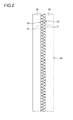
Fig. 1 is a front view illustrating an embodiment of a slide fastener according to the present invention, -
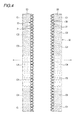
Fig. 2 is a front view illustrating a fastener chain before coloring, -
Fig. 3 is a front view illustrating the fastener chain after being colored by inkjet, -
Fig. 4 is a front view illustrating the fastener chain in a state where a pair of right and left fastener element rows are disengaged from each other, -
Fig. 5 is a front view illustrating the fastener chain in a state where one side of the pair of right and left fastener element rows is moved in a longitudinal direction thereof, -
Fig. 6 is a front view illustrating the fastener chain in a state where the pair of right and left fastener element rows are reengaged with each other, -
Fig. 7 is an enlarged front view illustrating a case where a location of each boundary between colors does not coincide in the right and left sides, -
Fig. 8 is a schematic view illustrating an inkjet type fastener chain coloring apparatus, -
Fig. 9 is a schematic view illustrating a transfer film type fastener chain coloring apparatus, -
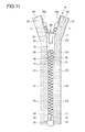
Fig. 10 is a front view illustrating a first variant of the embodiment of the slide fastener according to the invention, -
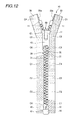
Fig. 11 is a front view illustrating a second variant of the embodiment of the slide fastener according to the invention, and -
Fig. 12 is a front view illustrating a third variant of the embodiment of the slide fastener according to the invention. - Hereinafter, embodiments of a method for manufacturing a slide fastener and a slide fastener according to the present invention will be described in detail with reference to the accompanying drawings. In the following description, as for slide fastener, a front side refers to a near side with respect to the paper surface of
Fig. 1 , a back side refers to a far side with respect to the paper surface ofFig. 1 , an upper side refers to an upper side with respect to the paper surface ofFig. 1 , a lower side refers to a lower side with respect to the paper surface ofFig. 1 , a left side refers to a left side with respect to the paper surface ofFig. 1 , and a right side refers to a right side with respect to the paper surface ofFig. 1 . In addition, the right and left direction of the slide fastener is also referred to as a width direction. The upward-downward direction of the slide fastener is also referred to as a longitudinal direction. - As shown in
Fig. 1 , theslide fastener 10 according to the present embodiment includes a pair of right and left woven or knittedfastener tapes 20, each of opposing tapeside edge portions 20a of the pair of right andleft fastener tapes 20 have an enlarged core portion, a pair of right and leftfastener element rows 30 respectively provided on the tapeside edge portions 20a, and each having a plurality offastener elements 31, aslider 40 configured to engage and disengage the pair of right and leftfastener element rows 30,top end stops 11 respectively provided on upper end portions of the pair of right and leftfastener element rows 30, andopeners 12 respectively provided on lower end portions of the pair of right and leftfastener element rows 30. As used herein, the term enlarged means that the core portion is raised in a front-back direction of thefastener tapes 20. - Each opener12 includes a
box pin 13 and abox body 14, which are formed on a lower end portion of the tapeside edge portion 20a of theright fastener tape 20, and aninsert pin 15 formed on a lower end portion of the tapeside edge portion 20a of theleft fastener tape 20 and adapted to be inserted into thebox body 14. Alternatively, the opener12 may be substituted with bottom end stops. - Each
fastener element row 30 is constituted of the plurality offastener elements 31 and thefastener elements 31 are injection-molded on the enlarged-shaped tape side edge portion 21a of thefastener tape 20, for example using polybutylene terephthalate or polyacetal. Also, polyester is used as a material for thefastener tape 20. - As shown in
Fig. 1 , theslider 40 includes abody 41, a pulltab attachment section 42 provided on a surface of thebody 41, and apull tab 43 attached to the pulltab attachment section 42. By moving theslider 40 toward the top end stops 11, the pair of right and leftfastener element rows 30 are engaged with each other, and by moving theslider 40 toward theopener 12, the pair of right and leftfastener element rows 30 are disengaged from each other. - According to the present embodiment, as shown in
Fig. 1 , the right andleft fastener tapes 20 and the right and leftfastener element rows 30 are colored in a plurality of colors (tints) C1 to C6 at a predetermined interval in the longitudinal direction by inkjet, in such a manner that a color (tint) is different in the right and left sides. More specifically, right and left colors C1 to C6 are arranged such that the same color is not overlapped in the width direction. Alternatively, the right and left colors C1 to C6 may be arranged such that the same color is partially overlapped in the width direction. In addition, a location of each boundary between colors C1 to C6 substantially coincides in the right and lefts, but is not limited thereto, and thus may not coincide in the left land light sides (seeFig. 7 ). Also, the color (tint) is not limited to a single color, but may be a pattern which is represented by a plurality of colors. Further, in the present embodiment, the number of colors is six, but is not limited thereto, and thus the number of colors is optional. - Meanwhile, symbols '/', 'V', '\', '+', '-', '•', shown in the drawings, are not patterns, but represent respectively regions of colors C1 to C6, in which a region represented by the symbol '/' is a region colored in a first color C1, a region represented by the symbol 'V' is a region colored in a second color C2, a region represented by the symbol '\' is a region colored in a third color C3, a region represented by the symbol '+' is a region colored in a fourth color C4, a region represented by the symbol '-' is a region colored in a fifth color C5, and a region represented by the symbol '•' is a region colored in a sixth color C6.
- Also, the colors C1 to C6 may include, for example, red, blue, green, yellow, purple, brown, pink, orange, black colors and the like. Meanwhile, the colors C1 to C6 are not limited to such colors. Each boundary between the colors C1 to C6 may be configured so that the colors are gradually changed from one another.
- Next, an embodiment of a method for manufacturing a slide fastener according to the present invention will be described with reference to
Figs. 2 to 6 . - The method for manufacturing the
slide fastener 10 according to the present embodiment incudes the steps of: preparing afastener chain 50 by engaging a pair of right and leftfastener element rows 30 with each other (seeFig. 2 ), coloring a pair of right and leftfastener tapes 20 and the pair of right and leftfastener element rows 30 of thefastener chain 50 in a plurality of colors C1 to C6 at a predetermined interval in the longitudinal direction by inkjet (seeFig. 3 ), disengaging the pair of right and left fastener element rows 30 (seeFig. 4 ), moving theleft fastener tape 20 in the longitudinal direction (downward direction inFig. 5 ) (seeFig. 5 ), and reengaging the right and left fastener element rows 30 (seeFig. 6 ). Meanwhile, thefastener tapes 20 and thefastener element rows 30 of thefastener chain 50 are initially colored in a single color, for example, white color. - Alternatively, in the step of moving the
fastener tape 20 in the longitudinal direction, theright fastener tape 20 may be moved, instead of theleft fastener tape 20. In addition, in the step of moving thefastener tape 20 in the longitudinal direction, thefastener tape 20 may be moved in an upward direction inFig. 5 , instead of the downward direction inFig. 5 . Further, in the embodiment, thefastener tape 20 is moved by an amount corresponding to three colors, but the movement amount is optional. - Now, a fastener
chain coloring apparatus 60 employed in the manufacturing method as described above will be described with reference toFig. 8 . - As shown in
Fig. 8 , the fastenerchain coloring apparatus 60 includes a conveyingunit 61 having a drivingroller 61a and a drivenroller 61b for conveying thefastener chain 50, twoguide rollers fastener chain 50, acoloring unit 64 arranged between theguide roller 62 and the conveyingunit 61 for coloring a surface of the conveyedfastener chain 50 in a predetermined color (tint) by inkjet, and acollection roller 65 for winding thecolored fastener chain 50 in a drum shape. - As described above, the method for manufacturing the
slide fastener 10 according to the present invention includes the steps of: coloring the pair of right and leftfastener tapes 20 and the pair of right and leftfastener element rows 30 in a plurality of colors C1 to C6 at a predetermined interval in the longitudinal direction by inkjet while the pair of right and leftfastener element rows 30 are engaged with each other to provide thefastener chain 50, disengaging the pair of right and leftfastener element rows 30, moving one of the pair of right and leftfastener tapes 20 in the longitudinal direction, and reengaging the right and leftfastener element rows 30. Accordingly, even if the right and leftfastener tapes 20 and the right and leftfastener element rows 30 are colored in a plurality of colors C1 to C6 at the predetermined interval in the longitudinal direction in such a manner that a color is different in the right and left sides, an increase in manufacturing cost of theslide fastener 10 can be inhibited and production efficiency thereof can be enhanced. - Alternatively, the coloring step of the method for manufacturing the slide fastener may be carried out by transferring, instead of inkjet. Also, in such transferring, a transfer film type fastener
chain coloring apparatus 70 shown inFig. 9 is employed. - As shown in
Fig. 9 , the fastenerchain coloring apparatus 70 includes achain supplying roll 71 for supplying afastener chain 50, achain winding roll 72 for collecting thecolored fastener chain 50, afilm supplying roll 73 for supplying atransfer film 51 onto thefastener chain 50, afilm winding roll 74 for collecting thetransfer film 51 after transferring, and a conveyingunit 75 having a drivingroller 75a and apressing roller 75b for conveying thefastener chain 50 and thetransfer film 51. Also, thepressing roller 75b of the conveyingunit 75 has a heater equipped therein, and a color (tint) of thetransfer film 51 is transferred to thefastener chain 50 by heat from the heater. In addition, thetransfer film 51 has different colors (tints) printed thereon at the predetermined interval in a longitudinal direction thereof. - Alternatively, as a first variant of the method for manufacturing the slide fastener according to the present embodiment, during the coloring step, the pair of right and left
fastener element rows 30 only may be colored in a plurality of colors C1 to C6 at the predetermined interval in the longitudinal direction by inkjet or transferring. As a result, as shown inFig. 10 , the pair of right and leftfastener element rows 30 is colored in a plurality of colors (tints) C1 to C6 at the predetermined interval in the longitudinal direction by inkjet in such a manner that a color is different in the right and left sides. - Also, as a second variant of the method for manufacturing the slide fastener according to the present embodiment, during the coloring step, the pair of right and left
fastener tapes 20 only may be colored in a plurality of colors C1 to C6 at the predetermined interval in the longitudinal direction by inkjet or transferring. As a result, as shown inFig. 11 , the pair of right and leftfastener tapes 20 is colored in a plurality of colors (tints) C1 to C6 at the predetermined interval in the longitudinal direction by inkjet in such a manner that a color is different in the right and left sides. - Further, as a third variant of the method for manufacturing the slide fastener according to the present embodiment, during the coloring step, portions (portions corresponding to the color C6) of the pair of right and left
fastener tapes 20 and the pair of right and leftfastener element rows 30 may not be colored by inkjet or transferring. As a result, as shown inFig. 12 , an original color of thefastener tapes 20 and thefastener element rows 30 appears intact on the uncolored portions. - The present invention is not limited to those that were illustrated in the foregoing embodiments but can be suitably changed without departing from the concept of the present invention.
- For example, although in the present embodiment at least one of the fastener tapes and the fastener element rows is colored, the present invention is not limited thereto, and thus the top end stops, the bottom end stops and the opener may be also colored.
-
- 10
- Slide Fastener
- 20
- Fastener Tape
- 20a
- Tape Side Edge Portion
- 30
- Fastener Element Row
- 31
- Fastener Element
- 50
- Fastener Chain
- C1 to C6
- Colors (Tints)
Claims (3)
- A method for manufacturing a slide fastener, the slide fastener comprising:a pair of right and left fastener tapes (20);a pair of right and left fastener element rows (30) respectively provided on opposing tape side edge portions (20a) of the pair of right and left fastener tapes, each of the fastener element rows having a plurality of fastener elements (31); anda slider (40) configured to engage and disengage the pair of right and left fastener element rows;the method comprising:coloring at least one of the pair of right and left fastener tapes and the pair of right and left fastener element rows in a plurality of colors (C1 to C6) at a predetermined interval in a longitudinal direction by inkjet while the pair of right and left fastener element rows are engaged with each other to provide a fastener chain (50);disengaging the pair of right and left fastener element rows;moving one of the pair of right and left fastener tapes in the longitudinal direction; andreengaging the right and left fastener element rows.
- A method for manufacturing a slide fastener, the slide fastener comprising:a pair of right and left fastener tapes (20);a pair of right and left fastener element rows (30) respectively provided on opposing tape side edge portions (20a) of the pair of right and left fastener tapes, each of the fastener element rows having a plurality of fastener elements (31); anda slider (40) configured to engage and disengage the pair of right and left fastener element rows;the method comprising:coloring at least one of the pair of right and left fastener tapes and the pair of right and left fastener element rows in a plurality of colors (C1 to C6) at a predetermined interval in a longitudinal direction by transferring while the pair of right and left fastener element rows are engaged with each other to provide a fastener chain (50);disengaging the pair of right and left fastener element rows;moving one of the pair of right and left fastener tapes in the longitudinal direction; andreengaging the right and left fastener element rows.
- A slide fastener manufactured by the method for manufacturing the slide fastener, according to claim 1 or 2.
Applications Claiming Priority (1)
| Application Number | Priority Date | Filing Date | Title |
|---|---|---|---|
| PCT/JP2012/063808 WO2013179398A1 (en) | 2012-05-29 | 2012-05-29 | Slide fastener manufacturing method and slide fastener |
Publications (3)
| Publication Number | Publication Date |
|---|---|
| EP2856902A1 true EP2856902A1 (en) | 2015-04-08 |
| EP2856902A4 EP2856902A4 (en) | 2015-12-30 |
| EP2856902B1 EP2856902B1 (en) | 2017-08-23 |
Family
ID=49672652
Family Applications (1)
| Application Number | Title | Priority Date | Filing Date |
|---|---|---|---|
| EP12877680.4A Active EP2856902B1 (en) | 2012-05-29 | 2012-05-29 | Slide fastener manufacturing method and slide fastener |
Country Status (5)
| Country | Link |
|---|---|
| US (1) | US9434113B2 (en) |
| EP (1) | EP2856902B1 (en) |
| CN (1) | CN104470399B (en) |
| TW (1) | TWI477242B (en) |
| WO (1) | WO2013179398A1 (en) |
Families Citing this family (8)
| Publication number | Priority date | Publication date | Assignee | Title |
|---|---|---|---|---|
| CN106061312B (en) * | 2014-05-15 | 2019-04-26 | Ykk株式会社 | Zipper stringer and manufacturing method of zipper stringer |
| DE112014007104B4 (en) * | 2014-10-27 | 2023-05-17 | Ykk Corporation | Zipper and method of manufacturing a zipper |
| CN106476460A (en) * | 2015-09-02 | 2017-03-08 | 吉田拉链(深圳)有限公司 | Zipper tooth surface treatment method and the zipper tooth using the method coloring, slide fastener and clothes |
| USD818394S1 (en) * | 2016-06-30 | 2018-05-22 | Ideal Fastener (Guangdong) Industries Ltd. | Zipper tooth |
| CN108748861B (en) * | 2018-08-02 | 2024-12-13 | 广州金吉拉链制造有限公司 | Zipper making equipment |
| KR102129972B1 (en) * | 2019-03-26 | 2020-07-03 | 주식회사 디엔지솔루션 | Printable and waterproofable zipper and the manufacturing method of the same |
| US12042026B2 (en) * | 2020-02-27 | 2024-07-23 | Ykk Corporation | Slide fastener |
| WO2023102394A2 (en) | 2021-11-30 | 2023-06-08 | Sierracrete Llc | Composite cellulosic products and processes for making and using same |
Family Cites Families (22)
| Publication number | Priority date | Publication date | Assignee | Title |
|---|---|---|---|---|
| US2911346A (en) * | 1952-07-29 | 1959-11-03 | Samuel L Cohn | Apparatus for electrolytic treatment of slide fasteners |
| US2991528A (en) * | 1959-03-03 | 1961-07-11 | Irving Constant | Metal slide fasteners and method of making same |
| US3939547A (en) * | 1974-08-28 | 1976-02-24 | Textron, Inc. | Method of producing a dyeable coating on metal article |
| JPS61293822A (en) | 1985-06-22 | 1986-12-24 | Yoshida Kogyo Kk <Ykk> | Manufacture of multi-color zip fastener |
| JPH0659247B2 (en) * | 1989-08-23 | 1994-08-10 | 吉田工業株式会社 | Slide fastener manufacturing method |
| AU620732B2 (en) * | 1989-09-12 | 1992-02-20 | Ykk Corporation | Method of and apparatus for manufacturing slide fasteners |
| JPH0424004A (en) * | 1990-05-21 | 1992-01-28 | Daiichi Seni Kako Kk | Slide fastener with pattern, and process and apparatus for dyeing its pattern |
| JPH0796750B2 (en) * | 1990-10-13 | 1995-10-18 | ワイケイケイ株式会社 | Color changer for continuous spray dyeing |
| JPH04367603A (en) * | 1991-06-15 | 1992-12-18 | Yoshida Kogyo Kk <Ykk> | Fastener element for slider fastener |
| JPH08126503A (en) * | 1994-10-31 | 1996-05-21 | Ykk Kk | Fastener chain continuous patterning device |
| JPH1170007A (en) | 1997-08-29 | 1999-03-16 | Ykk Corp | Tape for slide fastener and stringer for slide fastener |
| JPH1170005A (en) | 1997-08-29 | 1999-03-16 | Ykk Corp | Chain for slide fastener |
| TW379170B (en) * | 1998-05-07 | 2000-01-11 | Kang Young Chul | Color slide fastener and method and apparatus producing color slide fastener |
| TW413621B (en) * | 1998-09-25 | 2000-12-01 | Dar Shyan Ind Co Ltd | Method of producing zipper having chain teeth with metallic multi-color on its surface |
| KR100428608B1 (en) * | 2001-04-20 | 2004-04-29 | 영 철 강 | Apparatus manufacturing multi color slide fastener |
| JP2003180410A (en) * | 2001-12-14 | 2003-07-02 | Ykk Corp | Method for manufacturing slide fastener and adherend with constituent member |
| JP4071095B2 (en) * | 2002-12-04 | 2008-04-02 | Ykk株式会社 | Reflective slide fastener |
| US20050217085A1 (en) * | 2004-04-05 | 2005-10-06 | Lu Chi C | Structure of a patterned zipper |
| TWM263798U (en) * | 2004-09-10 | 2005-05-11 | Keen Ching Ind Co Ltd | Slide fastener with sectional multicolor metal sprockets |
| JP2007307245A (en) * | 2006-05-19 | 2007-11-29 | Ykk Corp | Temperature-sensitive discolored tape |
| US20080000064A1 (en) * | 2006-06-28 | 2008-01-03 | Ching Song Chou | Method of Manufacturing Color Metal Zipper and Apparatus Therefor |
| WO2011125176A1 (en) * | 2010-04-06 | 2011-10-13 | Ykk株式会社 | Fastener stringer and slide fastener |
-
2012
- 2012-05-29 WO PCT/JP2012/063808 patent/WO2013179398A1/en not_active Ceased
- 2012-05-29 EP EP12877680.4A patent/EP2856902B1/en active Active
- 2012-05-29 US US14/404,295 patent/US9434113B2/en active Active
- 2012-05-29 CN CN201280074819.1A patent/CN104470399B/en active Active
-
2013
- 2013-05-21 TW TW102117938A patent/TWI477242B/en active
Also Published As
| Publication number | Publication date |
|---|---|
| CN104470399A (en) | 2015-03-25 |
| US20150151499A1 (en) | 2015-06-04 |
| TWI477242B (en) | 2015-03-21 |
| EP2856902A4 (en) | 2015-12-30 |
| WO2013179398A1 (en) | 2013-12-05 |
| EP2856902B1 (en) | 2017-08-23 |
| CN104470399B (en) | 2018-01-02 |
| TW201350043A (en) | 2013-12-16 |
| US9434113B2 (en) | 2016-09-06 |
Similar Documents
| Publication | Publication Date | Title |
|---|---|---|
| US9434113B2 (en) | Slide fastener manufacturing method | |
| EP2856901B1 (en) | Slide fastener | |
| EP2638820B1 (en) | Sliding fastener | |
| CN103826493B (en) | The manufacture method of slide fastener and slide fastener | |
| DE112011105638T5 (en) | Zipper and method of making a zipper | |
| US2287263A (en) | Apparatus for assembling slide fastener stringers | |
| EP2705770B1 (en) | Decorated slide fastener tapes | |
| DE112012005338T5 (en) | Closing carrier, zipper for luggage bag and luggage bag | |
| CN107224041B (en) | Back zipper with secondary colors | |
| EP0111233B1 (en) | Curved slide fastener chain and method for producing curved slide fastener | |
| CN203378643U (en) | Zipper | |
| TWI624231B (en) | Zipper chain belt manufacturing method and zipper chain belt | |
| KR860002987A (en) | Manufacturing method of detachable slide fastener | |
| JP3525089B2 (en) | String film | |
| CN206933546U (en) | A kind of back of the body of secondary color zips | |
| CN103473988A (en) | Color card device for colored spinning and method for arranging cards of color card device | |
| JP2001145506A (en) | Slide fastener with pattern and method for fabricating the same | |
| CN220442070U (en) | Zipper with multicolor visual effect | |
| CN106714610B (en) | Slide fastener and method for manufacturing slide fastener | |
| DE102023117403A1 (en) | ZIPPER AND METHOD FOR PRODUCING A WATERPROOF ZIPPER CHAIN | |
| KR101826422B1 (en) | Label connector and manufacturing apparatus and manufacturing method thereof | |
| CN118660653A (en) | zipper | |
| KR20190012916A (en) | Plastic zipper | |
| ITTO970234A1 (en) | DEVICE FOR THE SUPPORT AND CONTROL OF A PACKAGE COLLECTABLE Awning. | |
| HK1154763A (en) | Slide fastener with decorative members and method for manufacturing thereof |
Legal Events
| Date | Code | Title | Description |
|---|---|---|---|
| PUAI | Public reference made under article 153(3) epc to a published international application that has entered the european phase |
Free format text: ORIGINAL CODE: 0009012 |
|
| 17P | Request for examination filed |
Effective date: 20141229 |
|
| AK | Designated contracting states |
Kind code of ref document: A1 Designated state(s): AL AT BE BG CH CY CZ DE DK EE ES FI FR GB GR HR HU IE IS IT LI LT LU LV MC MK MT NL NO PL PT RO RS SE SI SK SM TR |
|
| AX | Request for extension of the european patent |
Extension state: BA ME |
|
| DAX | Request for extension of the european patent (deleted) | ||
| RA4 | Supplementary search report drawn up and despatched (corrected) |
Effective date: 20151202 |
|
| RIC1 | Information provided on ipc code assigned before grant |
Ipc: A44B 19/42 20060101AFI20151126BHEP |
|
| 17Q | First examination report despatched |
Effective date: 20160803 |
|
| RIC1 | Information provided on ipc code assigned before grant |
Ipc: A44B 19/52 20060101AFI20170106BHEP Ipc: B21D 53/52 20060101ALI20170106BHEP Ipc: B29D 5/02 20060101ALN20170106BHEP Ipc: B29D 5/00 20060101ALI20170106BHEP |
|
| REG | Reference to a national code |
Ref country code: DE Ref legal event code: R079 Ref document number: 602012036475 Country of ref document: DE Free format text: PREVIOUS MAIN CLASS: A44B0019420000 Ipc: A44B0019520000 |
|
| GRAP | Despatch of communication of intention to grant a patent |
Free format text: ORIGINAL CODE: EPIDOSNIGR1 |
|
| RIC1 | Information provided on ipc code assigned before grant |
Ipc: B21D 53/52 20060101ALI20170224BHEP Ipc: B29D 5/02 20060101ALN20170224BHEP Ipc: B29D 5/00 20060101ALI20170224BHEP Ipc: A44B 19/52 20060101AFI20170224BHEP |
|
| INTG | Intention to grant announced |
Effective date: 20170314 |
|
| RIN1 | Information on inventor provided before grant (corrected) |
Inventor name: YAMAKITA, YOSHIMICHI |
|
| GRAS | Grant fee paid |
Free format text: ORIGINAL CODE: EPIDOSNIGR3 |
|
| GRAA | (expected) grant |
Free format text: ORIGINAL CODE: 0009210 |
|
| AK | Designated contracting states |
Kind code of ref document: B1 Designated state(s): AL AT BE BG CH CY CZ DE DK EE ES FI FR GB GR HR HU IE IS IT LI LT LU LV MC MK MT NL NO PL PT RO RS SE SI SK SM TR |
|
| REG | Reference to a national code |
Ref country code: GB Ref legal event code: FG4D |
|
| REG | Reference to a national code |
Ref country code: CH Ref legal event code: EP |
|
| REG | Reference to a national code |
Ref country code: AT Ref legal event code: REF Ref document number: 920335 Country of ref document: AT Kind code of ref document: T Effective date: 20170915 |
|
| REG | Reference to a national code |
Ref country code: IE Ref legal event code: FG4D |
|
| REG | Reference to a national code |
Ref country code: DE Ref legal event code: R096 Ref document number: 602012036475 Country of ref document: DE |
|
| REG | Reference to a national code |
Ref country code: NL Ref legal event code: MP Effective date: 20170823 |
|
| REG | Reference to a national code |
Ref country code: LT Ref legal event code: MG4D |
|
| REG | Reference to a national code |
Ref country code: AT Ref legal event code: MK05 Ref document number: 920335 Country of ref document: AT Kind code of ref document: T Effective date: 20170823 |
|
| PG25 | Lapsed in a contracting state [announced via postgrant information from national office to epo] |
Ref country code: NO Free format text: LAPSE BECAUSE OF FAILURE TO SUBMIT A TRANSLATION OF THE DESCRIPTION OR TO PAY THE FEE WITHIN THE PRESCRIBED TIME-LIMIT Effective date: 20171123 Ref country code: AT Free format text: LAPSE BECAUSE OF FAILURE TO SUBMIT A TRANSLATION OF THE DESCRIPTION OR TO PAY THE FEE WITHIN THE PRESCRIBED TIME-LIMIT Effective date: 20170823 Ref country code: LT Free format text: LAPSE BECAUSE OF FAILURE TO SUBMIT A TRANSLATION OF THE DESCRIPTION OR TO PAY THE FEE WITHIN THE PRESCRIBED TIME-LIMIT Effective date: 20170823 Ref country code: FI Free format text: LAPSE BECAUSE OF FAILURE TO SUBMIT A TRANSLATION OF THE DESCRIPTION OR TO PAY THE FEE WITHIN THE PRESCRIBED TIME-LIMIT Effective date: 20170823 Ref country code: SE Free format text: LAPSE BECAUSE OF FAILURE TO SUBMIT A TRANSLATION OF THE DESCRIPTION OR TO PAY THE FEE WITHIN THE PRESCRIBED TIME-LIMIT Effective date: 20170823 Ref country code: HR Free format text: LAPSE BECAUSE OF FAILURE TO SUBMIT A TRANSLATION OF THE DESCRIPTION OR TO PAY THE FEE WITHIN THE PRESCRIBED TIME-LIMIT Effective date: 20170823 Ref country code: NL Free format text: LAPSE BECAUSE OF FAILURE TO SUBMIT A TRANSLATION OF THE DESCRIPTION OR TO PAY THE FEE WITHIN THE PRESCRIBED TIME-LIMIT Effective date: 20170823 |
|
| PG25 | Lapsed in a contracting state [announced via postgrant information from national office to epo] |
Ref country code: GR Free format text: LAPSE BECAUSE OF FAILURE TO SUBMIT A TRANSLATION OF THE DESCRIPTION OR TO PAY THE FEE WITHIN THE PRESCRIBED TIME-LIMIT Effective date: 20171124 Ref country code: LV Free format text: LAPSE BECAUSE OF FAILURE TO SUBMIT A TRANSLATION OF THE DESCRIPTION OR TO PAY THE FEE WITHIN THE PRESCRIBED TIME-LIMIT Effective date: 20170823 Ref country code: ES Free format text: LAPSE BECAUSE OF FAILURE TO SUBMIT A TRANSLATION OF THE DESCRIPTION OR TO PAY THE FEE WITHIN THE PRESCRIBED TIME-LIMIT Effective date: 20170823 Ref country code: BG Free format text: LAPSE BECAUSE OF FAILURE TO SUBMIT A TRANSLATION OF THE DESCRIPTION OR TO PAY THE FEE WITHIN THE PRESCRIBED TIME-LIMIT Effective date: 20171123 Ref country code: RS Free format text: LAPSE BECAUSE OF FAILURE TO SUBMIT A TRANSLATION OF THE DESCRIPTION OR TO PAY THE FEE WITHIN THE PRESCRIBED TIME-LIMIT Effective date: 20170823 Ref country code: PL Free format text: LAPSE BECAUSE OF FAILURE TO SUBMIT A TRANSLATION OF THE DESCRIPTION OR TO PAY THE FEE WITHIN THE PRESCRIBED TIME-LIMIT Effective date: 20170823 Ref country code: IS Free format text: LAPSE BECAUSE OF FAILURE TO SUBMIT A TRANSLATION OF THE DESCRIPTION OR TO PAY THE FEE WITHIN THE PRESCRIBED TIME-LIMIT Effective date: 20171223 |
|
| PG25 | Lapsed in a contracting state [announced via postgrant information from national office to epo] |
Ref country code: RO Free format text: LAPSE BECAUSE OF FAILURE TO SUBMIT A TRANSLATION OF THE DESCRIPTION OR TO PAY THE FEE WITHIN THE PRESCRIBED TIME-LIMIT Effective date: 20170823 Ref country code: DK Free format text: LAPSE BECAUSE OF FAILURE TO SUBMIT A TRANSLATION OF THE DESCRIPTION OR TO PAY THE FEE WITHIN THE PRESCRIBED TIME-LIMIT Effective date: 20170823 Ref country code: CZ Free format text: LAPSE BECAUSE OF FAILURE TO SUBMIT A TRANSLATION OF THE DESCRIPTION OR TO PAY THE FEE WITHIN THE PRESCRIBED TIME-LIMIT Effective date: 20170823 |
|
| REG | Reference to a national code |
Ref country code: DE Ref legal event code: R097 Ref document number: 602012036475 Country of ref document: DE |
|
| PG25 | Lapsed in a contracting state [announced via postgrant information from national office to epo] |
Ref country code: EE Free format text: LAPSE BECAUSE OF FAILURE TO SUBMIT A TRANSLATION OF THE DESCRIPTION OR TO PAY THE FEE WITHIN THE PRESCRIBED TIME-LIMIT Effective date: 20170823 Ref country code: SK Free format text: LAPSE BECAUSE OF FAILURE TO SUBMIT A TRANSLATION OF THE DESCRIPTION OR TO PAY THE FEE WITHIN THE PRESCRIBED TIME-LIMIT Effective date: 20170823 Ref country code: SM Free format text: LAPSE BECAUSE OF FAILURE TO SUBMIT A TRANSLATION OF THE DESCRIPTION OR TO PAY THE FEE WITHIN THE PRESCRIBED TIME-LIMIT Effective date: 20170823 |
|
| PLBE | No opposition filed within time limit |
Free format text: ORIGINAL CODE: 0009261 |
|
| STAA | Information on the status of an ep patent application or granted ep patent |
Free format text: STATUS: NO OPPOSITION FILED WITHIN TIME LIMIT |
|
| 26N | No opposition filed |
Effective date: 20180524 |
|
| PG25 | Lapsed in a contracting state [announced via postgrant information from national office to epo] |
Ref country code: SI Free format text: LAPSE BECAUSE OF FAILURE TO SUBMIT A TRANSLATION OF THE DESCRIPTION OR TO PAY THE FEE WITHIN THE PRESCRIBED TIME-LIMIT Effective date: 20170823 |
|
| REG | Reference to a national code |
Ref country code: DE Ref legal event code: R119 Ref document number: 602012036475 Country of ref document: DE |
|
| REG | Reference to a national code |
Ref country code: CH Ref legal event code: PL |
|
| GBPC | Gb: european patent ceased through non-payment of renewal fee |
Effective date: 20180529 |
|
| REG | Reference to a national code |
Ref country code: BE Ref legal event code: MM Effective date: 20180531 |
|
| PG25 | Lapsed in a contracting state [announced via postgrant information from national office to epo] |
Ref country code: MC Free format text: LAPSE BECAUSE OF FAILURE TO SUBMIT A TRANSLATION OF THE DESCRIPTION OR TO PAY THE FEE WITHIN THE PRESCRIBED TIME-LIMIT Effective date: 20170823 |
|
| REG | Reference to a national code |
Ref country code: IE Ref legal event code: MM4A |
|
| PG25 | Lapsed in a contracting state [announced via postgrant information from national office to epo] |
Ref country code: LI Free format text: LAPSE BECAUSE OF NON-PAYMENT OF DUE FEES Effective date: 20180531 Ref country code: CH Free format text: LAPSE BECAUSE OF NON-PAYMENT OF DUE FEES Effective date: 20180531 |
|
| PG25 | Lapsed in a contracting state [announced via postgrant information from national office to epo] |
Ref country code: LU Free format text: LAPSE BECAUSE OF NON-PAYMENT OF DUE FEES Effective date: 20180529 |
|
| PG25 | Lapsed in a contracting state [announced via postgrant information from national office to epo] |
Ref country code: GB Free format text: LAPSE BECAUSE OF NON-PAYMENT OF DUE FEES Effective date: 20180529 Ref country code: IE Free format text: LAPSE BECAUSE OF NON-PAYMENT OF DUE FEES Effective date: 20180529 Ref country code: DE Free format text: LAPSE BECAUSE OF NON-PAYMENT OF DUE FEES Effective date: 20181201 Ref country code: FR Free format text: LAPSE BECAUSE OF NON-PAYMENT OF DUE FEES Effective date: 20180531 |
|
| PG25 | Lapsed in a contracting state [announced via postgrant information from national office to epo] |
Ref country code: BE Free format text: LAPSE BECAUSE OF NON-PAYMENT OF DUE FEES Effective date: 20180531 |
|
| PG25 | Lapsed in a contracting state [announced via postgrant information from national office to epo] |
Ref country code: MT Free format text: LAPSE BECAUSE OF NON-PAYMENT OF DUE FEES Effective date: 20180529 |
|
| PG25 | Lapsed in a contracting state [announced via postgrant information from national office to epo] |
Ref country code: TR Free format text: LAPSE BECAUSE OF FAILURE TO SUBMIT A TRANSLATION OF THE DESCRIPTION OR TO PAY THE FEE WITHIN THE PRESCRIBED TIME-LIMIT Effective date: 20170823 |
|
| PG25 | Lapsed in a contracting state [announced via postgrant information from national office to epo] |
Ref country code: PT Free format text: LAPSE BECAUSE OF FAILURE TO SUBMIT A TRANSLATION OF THE DESCRIPTION OR TO PAY THE FEE WITHIN THE PRESCRIBED TIME-LIMIT Effective date: 20170823 |
|
| PG25 | Lapsed in a contracting state [announced via postgrant information from national office to epo] |
Ref country code: HU Free format text: LAPSE BECAUSE OF FAILURE TO SUBMIT A TRANSLATION OF THE DESCRIPTION OR TO PAY THE FEE WITHIN THE PRESCRIBED TIME-LIMIT; INVALID AB INITIO Effective date: 20120529 Ref country code: CY Free format text: LAPSE BECAUSE OF FAILURE TO SUBMIT A TRANSLATION OF THE DESCRIPTION OR TO PAY THE FEE WITHIN THE PRESCRIBED TIME-LIMIT Effective date: 20170823 Ref country code: MK Free format text: LAPSE BECAUSE OF NON-PAYMENT OF DUE FEES Effective date: 20170823 |
|
| PG25 | Lapsed in a contracting state [announced via postgrant information from national office to epo] |
Ref country code: AL Free format text: LAPSE BECAUSE OF FAILURE TO SUBMIT A TRANSLATION OF THE DESCRIPTION OR TO PAY THE FEE WITHIN THE PRESCRIBED TIME-LIMIT Effective date: 20170823 |
|
| P01 | Opt-out of the competence of the unified patent court (upc) registered |
Effective date: 20230428 |
|
| PGFP | Annual fee paid to national office [announced via postgrant information from national office to epo] |
Ref country code: IT Payment date: 20250422 Year of fee payment: 14 |