EP2856925B1 - Appareil de source lumineuse et appareil d'endoscope - Google Patents
Appareil de source lumineuse et appareil d'endoscope Download PDFInfo
- Publication number
- EP2856925B1 EP2856925B1 EP14186397.7A EP14186397A EP2856925B1 EP 2856925 B1 EP2856925 B1 EP 2856925B1 EP 14186397 A EP14186397 A EP 14186397A EP 2856925 B1 EP2856925 B1 EP 2856925B1
- Authority
- EP
- European Patent Office
- Prior art keywords
- light
- blue
- light source
- green
- source apparatus
- Prior art date
- Legal status (The legal status is an assumption and is not a legal conclusion. Google has not performed a legal analysis and makes no representation as to the accuracy of the status listed.)
- Active
Links
Images











Classifications
-
- H—ELECTRICITY
- H05—ELECTRIC TECHNIQUES NOT OTHERWISE PROVIDED FOR
- H05B—ELECTRIC HEATING; ELECTRIC LIGHT SOURCES NOT OTHERWISE PROVIDED FOR; CIRCUIT ARRANGEMENTS FOR ELECTRIC LIGHT SOURCES, IN GENERAL
- H05B45/00—Circuit arrangements for operating light-emitting diodes [LED]
- H05B45/10—Controlling the intensity of the light
- H05B45/12—Controlling the intensity of the light using optical feedback
-
- A—HUMAN NECESSITIES
- A61—MEDICAL OR VETERINARY SCIENCE; HYGIENE
- A61B—DIAGNOSIS; SURGERY; IDENTIFICATION
- A61B1/00—Instruments for performing medical examinations of the interior of cavities or tubes of the body by visual or photographical inspection, e.g. endoscopes; Illuminating arrangements therefor
- A61B1/00002—Operational features of endoscopes
- A61B1/00057—Operational features of endoscopes provided with means for testing or calibration
-
- A—HUMAN NECESSITIES
- A61—MEDICAL OR VETERINARY SCIENCE; HYGIENE
- A61B—DIAGNOSIS; SURGERY; IDENTIFICATION
- A61B1/00—Instruments for performing medical examinations of the interior of cavities or tubes of the body by visual or photographical inspection, e.g. endoscopes; Illuminating arrangements therefor
- A61B1/06—Instruments for performing medical examinations of the interior of cavities or tubes of the body by visual or photographical inspection, e.g. endoscopes; Illuminating arrangements therefor with illuminating arrangements
- A61B1/0638—Instruments for performing medical examinations of the interior of cavities or tubes of the body by visual or photographical inspection, e.g. endoscopes; Illuminating arrangements therefor with illuminating arrangements providing two or more wavelengths
-
- A—HUMAN NECESSITIES
- A61—MEDICAL OR VETERINARY SCIENCE; HYGIENE
- A61B—DIAGNOSIS; SURGERY; IDENTIFICATION
- A61B1/00—Instruments for performing medical examinations of the interior of cavities or tubes of the body by visual or photographical inspection, e.g. endoscopes; Illuminating arrangements therefor
- A61B1/06—Instruments for performing medical examinations of the interior of cavities or tubes of the body by visual or photographical inspection, e.g. endoscopes; Illuminating arrangements therefor with illuminating arrangements
- A61B1/0646—Instruments for performing medical examinations of the interior of cavities or tubes of the body by visual or photographical inspection, e.g. endoscopes; Illuminating arrangements therefor with illuminating arrangements with illumination filters
-
- A—HUMAN NECESSITIES
- A61—MEDICAL OR VETERINARY SCIENCE; HYGIENE
- A61B—DIAGNOSIS; SURGERY; IDENTIFICATION
- A61B1/00—Instruments for performing medical examinations of the interior of cavities or tubes of the body by visual or photographical inspection, e.g. endoscopes; Illuminating arrangements therefor
- A61B1/06—Instruments for performing medical examinations of the interior of cavities or tubes of the body by visual or photographical inspection, e.g. endoscopes; Illuminating arrangements therefor with illuminating arrangements
- A61B1/0653—Instruments for performing medical examinations of the interior of cavities or tubes of the body by visual or photographical inspection, e.g. endoscopes; Illuminating arrangements therefor with illuminating arrangements with wavelength conversion
-
- A—HUMAN NECESSITIES
- A61—MEDICAL OR VETERINARY SCIENCE; HYGIENE
- A61B—DIAGNOSIS; SURGERY; IDENTIFICATION
- A61B1/00—Instruments for performing medical examinations of the interior of cavities or tubes of the body by visual or photographical inspection, e.g. endoscopes; Illuminating arrangements therefor
- A61B1/06—Instruments for performing medical examinations of the interior of cavities or tubes of the body by visual or photographical inspection, e.g. endoscopes; Illuminating arrangements therefor with illuminating arrangements
- A61B1/0655—Control therefor
-
- A—HUMAN NECESSITIES
- A61—MEDICAL OR VETERINARY SCIENCE; HYGIENE
- A61B—DIAGNOSIS; SURGERY; IDENTIFICATION
- A61B1/00—Instruments for performing medical examinations of the interior of cavities or tubes of the body by visual or photographical inspection, e.g. endoscopes; Illuminating arrangements therefor
- A61B1/06—Instruments for performing medical examinations of the interior of cavities or tubes of the body by visual or photographical inspection, e.g. endoscopes; Illuminating arrangements therefor with illuminating arrangements
- A61B1/0661—Endoscope light sources
-
- A—HUMAN NECESSITIES
- A61—MEDICAL OR VETERINARY SCIENCE; HYGIENE
- A61B—DIAGNOSIS; SURGERY; IDENTIFICATION
- A61B1/00—Instruments for performing medical examinations of the interior of cavities or tubes of the body by visual or photographical inspection, e.g. endoscopes; Illuminating arrangements therefor
- A61B1/06—Instruments for performing medical examinations of the interior of cavities or tubes of the body by visual or photographical inspection, e.g. endoscopes; Illuminating arrangements therefor with illuminating arrangements
- A61B1/0661—Endoscope light sources
- A61B1/0684—Endoscope light sources using light emitting diodes [LED]
-
- A—HUMAN NECESSITIES
- A61—MEDICAL OR VETERINARY SCIENCE; HYGIENE
- A61B—DIAGNOSIS; SURGERY; IDENTIFICATION
- A61B1/00—Instruments for performing medical examinations of the interior of cavities or tubes of the body by visual or photographical inspection, e.g. endoscopes; Illuminating arrangements therefor
- A61B1/06—Instruments for performing medical examinations of the interior of cavities or tubes of the body by visual or photographical inspection, e.g. endoscopes; Illuminating arrangements therefor with illuminating arrangements
- A61B1/07—Instruments for performing medical examinations of the interior of cavities or tubes of the body by visual or photographical inspection, e.g. endoscopes; Illuminating arrangements therefor with illuminating arrangements using light-conductive means, e.g. optical fibres
-
- G—PHYSICS
- G02—OPTICS
- G02B—OPTICAL ELEMENTS, SYSTEMS OR APPARATUS
- G02B23/00—Telescopes, e.g. binoculars; Periscopes; Instruments for viewing the inside of hollow bodies; Viewfinders; Optical aiming or sighting devices
- G02B23/24—Instruments or systems for viewing the inside of hollow bodies, e.g. fibrescopes
- G02B23/2407—Optical details
- G02B23/2461—Illumination
- G02B23/2469—Illumination using optical fibres
-
- G—PHYSICS
- G02—OPTICS
- G02B—OPTICAL ELEMENTS, SYSTEMS OR APPARATUS
- G02B6/00—Light guides; Structural details of arrangements comprising light guides and other optical elements, e.g. couplings
- G02B6/0001—Light guides; Structural details of arrangements comprising light guides and other optical elements, e.g. couplings specially adapted for lighting devices or systems
- G02B6/0005—Light guides; Structural details of arrangements comprising light guides and other optical elements, e.g. couplings specially adapted for lighting devices or systems the light guides being of the fibre type
-
- H—ELECTRICITY
- H10—SEMICONDUCTOR DEVICES; ELECTRIC SOLID-STATE DEVICES NOT OTHERWISE PROVIDED FOR
- H10H—INORGANIC LIGHT-EMITTING SEMICONDUCTOR DEVICES HAVING POTENTIAL BARRIERS
- H10H20/00—Individual inorganic light-emitting semiconductor devices having potential barriers, e.g. light-emitting diodes [LED]
- H10H20/80—Constructional details
- H10H20/85—Packages
- H10H20/851—Wavelength conversion means
-
- H—ELECTRICITY
- H10—SEMICONDUCTOR DEVICES; ELECTRIC SOLID-STATE DEVICES NOT OTHERWISE PROVIDED FOR
- H10H—INORGANIC LIGHT-EMITTING SEMICONDUCTOR DEVICES HAVING POTENTIAL BARRIERS
- H10H20/00—Individual inorganic light-emitting semiconductor devices having potential barriers, e.g. light-emitting diodes [LED]
- H10H20/80—Constructional details
- H10H20/85—Packages
- H10H20/855—Optical field-shaping means, e.g. lenses
-
- H—ELECTRICITY
- H10—SEMICONDUCTOR DEVICES; ELECTRIC SOLID-STATE DEVICES NOT OTHERWISE PROVIDED FOR
- H10H—INORGANIC LIGHT-EMITTING SEMICONDUCTOR DEVICES HAVING POTENTIAL BARRIERS
- H10H29/00—Integrated devices, or assemblies of multiple devices, comprising at least one light-emitting semiconductor element covered by group H10H20/00
- H10H29/10—Integrated devices comprising at least one light-emitting semiconductor component covered by group H10H20/00
-
- A—HUMAN NECESSITIES
- A61—MEDICAL OR VETERINARY SCIENCE; HYGIENE
- A61B—DIAGNOSIS; SURGERY; IDENTIFICATION
- A61B1/00—Instruments for performing medical examinations of the interior of cavities or tubes of the body by visual or photographical inspection, e.g. endoscopes; Illuminating arrangements therefor
- A61B1/04—Instruments for performing medical examinations of the interior of cavities or tubes of the body by visual or photographical inspection, e.g. endoscopes; Illuminating arrangements therefor combined with photographic or television appliances
- A61B1/043—Instruments for performing medical examinations of the interior of cavities or tubes of the body by visual or photographical inspection, e.g. endoscopes; Illuminating arrangements therefor combined with photographic or television appliances for fluorescence imaging
-
- G—PHYSICS
- G03—PHOTOGRAPHY; CINEMATOGRAPHY; ANALOGOUS TECHNIQUES USING WAVES OTHER THAN OPTICAL WAVES; ELECTROGRAPHY; HOLOGRAPHY
- G03B—APPARATUS OR ARRANGEMENTS FOR TAKING PHOTOGRAPHS OR FOR PROJECTING OR VIEWING THEM; APPARATUS OR ARRANGEMENTS EMPLOYING ANALOGOUS TECHNIQUES USING WAVES OTHER THAN OPTICAL WAVES; ACCESSORIES THEREFOR
- G03B2215/00—Special procedures for taking photographs; Apparatus therefor
- G03B2215/05—Combinations of cameras with electronic flash units
- G03B2215/0564—Combinations of cameras with electronic flash units characterised by the type of light source
- G03B2215/0567—Solid-state light source, e.g. LED, laser
-
- H—ELECTRICITY
- H10—SEMICONDUCTOR DEVICES; ELECTRIC SOLID-STATE DEVICES NOT OTHERWISE PROVIDED FOR
- H10W—GENERIC PACKAGES, INTERCONNECTIONS, CONNECTORS OR OTHER CONSTRUCTIONAL DETAILS OF DEVICES COVERED BY CLASS H10
- H10W72/00—Interconnections or connectors in packages
- H10W72/071—Connecting or disconnecting
- H10W72/075—Connecting or disconnecting of bond wires
- H10W72/07551—Connecting or disconnecting of bond wires characterised by changes in properties of the bond wires during the connecting
- H10W72/07554—Connecting or disconnecting of bond wires characterised by changes in properties of the bond wires during the connecting changes in dispositions
-
- H—ELECTRICITY
- H10—SEMICONDUCTOR DEVICES; ELECTRIC SOLID-STATE DEVICES NOT OTHERWISE PROVIDED FOR
- H10W—GENERIC PACKAGES, INTERCONNECTIONS, CONNECTORS OR OTHER CONSTRUCTIONAL DETAILS OF DEVICES COVERED BY CLASS H10
- H10W72/00—Interconnections or connectors in packages
- H10W72/50—Bond wires
- H10W72/541—Dispositions of bond wires
- H10W72/547—Dispositions of multiple bond wires
-
- H—ELECTRICITY
- H10—SEMICONDUCTOR DEVICES; ELECTRIC SOLID-STATE DEVICES NOT OTHERWISE PROVIDED FOR
- H10W—GENERIC PACKAGES, INTERCONNECTIONS, CONNECTORS OR OTHER CONSTRUCTIONAL DETAILS OF DEVICES COVERED BY CLASS H10
- H10W74/00—Encapsulations, e.g. protective coatings
Definitions
- the present invention relates to a light source apparatus and endoscope system in which a fluorescent type of green semiconductor light source is used, and illumination light of an emission spectrum of a target for use in endoscopic imaging can be stably obtained.
- Endoscopic imaging with an endoscope system is widely known in the field of medical diagnosis.
- the endoscope system includes an endoscope, a light source apparatus and a processing apparatus.
- the light source apparatus supplies light to the endoscope.
- the processing apparatus processes an image signal output by the endoscope.
- the endoscope includes an elongated tube for entry in a body cavity.
- a tip of the elongated tube has lighting windows and a viewing window.
- the lighting windows apply the light to an object of interest in the body cavity.
- the viewing window receives object light from the object of interest for imaging.
- a light guide device is incorporated in the endoscope, and includes a fiber bundle of a plurality of optical fibers. The light guide device guides light from the light source apparatus to the lighting windows.
- An image sensor is disposed behind the viewing window, for example, CCD image sensor.
- the object of interest illuminated with the light is imaged by the image sensor, which outputs an image signal.
- the processing apparatus generates a display image of the image signal.
- a monitor display panel is driven to display the image, to observe the object of interest in the body cavity.
- JP-A 2007-068699 and U.S. Pat. Nos. 8, 337, 400 and 8, 506, 478 disclose use of semiconductor light sources such as laser diodes (LDs), light emitting diodes (LEDs) and the like for the purpose of the endoscopic imaging.
- LDs laser diodes
- LEDs light emitting diodes
- JP-A 2007-068699 discloses the light source apparatus, in which the semiconductor light sources have three LEDs to emit light of blue, green and red. Components of the light of blue, green and red are combined to produce the white light.
- the semiconductor light sources of blue, green and red are controllable for discretely adjusting light amounts of the colors. Illumination light of plural types can be produced easily with various spectra of emission.
- Examples of the semiconductor light sources of green include a green semiconductor light source having an element for emitting green light itself, and a fluorescent type of a semiconductor light source.
- the fluorescent type includes an excitation light source device for emitting excitation light, and green emitting phosphor excited by the excitation light for emitting green fluorescence.
- U.S. Pat. Nos. 8,337,400 and 8, 506, 478 disclose a fluorescent type of green semiconductor light source having a blue excitation light source device (blue LED) and green emitting phosphor.
- the blue excitation light source device emits blue excitation light in a violet to blue wavelength range.
- the green emitting phosphor is excited by the blue excitation light for emitting green fluorescence of a green wavelength range.
- a blue-violet LED for lighting in a violet to blue wavelength range is usable more widely than a green LED for lighting in a green wavelength range, because of such advantage that efficiency in the light emission of the blue-violet LED is higher than the green LED, and that its cost is lower. It is conceivable to use the fluorescent type of green semiconductor light source disclosed in U.S. Pat. Nos. 8,337,400 and 8, 506, 478 with a recently higher concern than the semiconductor light sources or green LED for emitting green light.
- narrow band imaging with narrow band light has been known recently in the field of the endoscopic imaging.
- the narrow band light is light of a limited wavelength range in contrast with the white light for imaging with the entirety of a surface of body tissue or the object of interest.
- depth of penetration of light into the body tissue is characteristically different between plural wavelengths.
- vessel enhancement imaging is performed to enhance part of blood vessels present in mucosa of the body tissue, as described in JP-A 2011-041758 .
- a state of the blood vessels in abnormal tissue such as a cancer is different from the normal tissue, so that the vessel enhancement imaging is useful for discovering an early state of a cancer in the diagnosis of cancer screening.
- Examples of the semiconductor light sources disclosed in JP-A 2011-041758 are a fluorescent type of white semiconductor light source and a green semiconductor light source.
- the fluorescent type of white semiconductor light source (white LED) emits the white light with a continuous spectrum extending fully in a visible light wavelength range.
- the green semiconductor light source (green LED) emits light of a green wavelength range of 530-550 nm.
- a band pass filter is disposed downstream of the fluorescent type of white semiconductor light source, and derives light of a blue wavelength range of 390-445 nm from the white light.
- the semiconductor light sources are turned on, so as to apply mixed light of the green light and blue light, the green light being emitted by the green semiconductor light source in the wavelength range of 530-550 nm, the blue light being passed through the band pass filter in the wavelength range of 390-445 nm upon emission of the white light from the fluorescent type of white semiconductor light source.
- the blue light of this wavelength range is highly absorbed by surface blood vessels present on the epithelium (mucosa surface) .
- the green light of this wavelength range is highly absorbed by subsurface or deep blood vessels disposed deeper than the surface blood vessels. A display image with a high contrast between the blood vessels and other tissue can be obtained.
- JP-A 2007-068699 the semiconductor light sources of blue, green and red are used for performing the vessel enhancement imaging with blue light from the blue semiconductor light source and green light from the green semiconductor light source.
- the fluorescent type of green semiconductor light source is used for the green light source.
- the combined construction of the light source apparatus has a drawback in that illumination light of an emission spectrum cannot be stably obtained as a target of the vessel enhancement imaging.
- the blue excitation light is largely absorbed by the green emitting phosphor.
- part of the blue excitation light is not absorbed by the green emitting phosphor, but passes the green emitting phosphor and becomes emitted to the object of interest together with the green fluorescence.
- Changing the light amount of the green light may change a light amount of the blue excitation light.
- the light amount of the blue light is influenced by the change in the light amount of the green light.
- GB 2 493 994 A discloses a light source apparatus having a blue semiconductor light source, a fluorescence type of a green semiconductor light source having a blue excitation light source device and a phosphor generating radiation comprising a broad band of wavelengths which span from blue to red (460 nm to 700 nm) to generate a bright white light. Further, a wavelength cut-off filter is disposed between the blue excitation light source and a light guide device.
- an object of the present invention is to provide a light source apparatus and endoscope system in which a fluorescent type of green semiconductor light source is used, and illumination light of an emission spectrum of a target for use in endoscopic imaging can be. stably obtained.
- a light source apparatus for supplying a light guide device of an endoscope with light includes the features of claim 1.
- a path coupler couples two light paths from the blue and green semiconductor light sources together.
- the wavelength cut-off filter component is disposed on the path coupler, or disposed between the path coupler and the green semiconductor light source.
- the path coupler includes optics disposed at an intersection point between the two light paths.
- the wavelength cut-off filter component is a dichroic filter formed on the optics.
- a driver simultaneously drives the blue and green semiconductor light sources for vessel enhancement imaging, to output mixed light of the blue light and the green fluorescence.
- a driver alternately drives the blue and green semiconductor light sources for vessel enhancement imaging, sequentially to output the blue light and the green fluorescence.
- a driver is connected to the blue and green semiconductor light sources, and changeable between simultaneous lighting and field sequential lighting.
- the driver simultaneously drives the blue and green semiconductor light sources for vessel enhancement imaging, to output mixed light of the blue light and the green fluorescence.
- the driver alternately drives the blue and green semiconductor light sources for vessel enhancement imaging, sequentially to output the blue light and the green fluorescence.
- the blue semiconductor light source emits the blue light with a peak wavelength of at least one of 405, 415, 430 and 460 nm.
- a measurement sensor measures a light amount of the blue light or the green fluorescence emitted by at least one of the blue and green semiconductor light sources.
- An optical path device guides part of the blue light or the green fluorescence to the measurement sensor.
- a light source controller controls power supplied to the blue or green semiconductor light source according to a measurement result of the measurement sensor.
- the measurement sensor and the optical path device are associated with the green semiconductor light source, and the light source controller adjusts the power supplied to the blue excitation light source device according to the measurement result.
- a band pass filter is disposed upstream of the measurement sensor, for receiving light emitted by the green semiconductor light source and reflected by the optical path device, and cutting off light with a wavelength different from the green wavelength range of the green fluorescence.
- the wavelength cut-off filter component is a wavelength cut-off filter of a plate shape disposed between the green semiconductor light source and the optical path device.
- the optical path device includes a transparent glass plate, disposed downstream of the blue or green semiconductor light source, for reflecting the part of the blue light or the green fluorescence by Fresnel reflection, to guide the part to the sensor.
- a rotatable disk has the green emitting phosphor formed on a surface thereof.
- the blue excitation light source device emits the blue excitation light toward the rotatable disk being rotated at an eccentric point thereof.
- an endoscope system including an endoscope having a light guide device for guiding light, and a light source apparatus for supplying the light guide device with the light.
- the light source apparatus includes the features defined by any of claims 1 to 14.
- illumination light of an emission spectrum of a target for use in endoscopic imaging can be stably obtained, because the wavelength cut-off filter component cuts off a part of the blue excitation light traveling in an unwanted manner.
- an endoscope system 10 includes an endoscope 11, a processing apparatus 12, a light source apparatus 13 and a monitor display panel 14.
- the endoscope 11 images an object of interest or body tissue.
- the processing apparatus 12 receives an image signal from the endoscope 11 and produces an image of the object of interest.
- the light source apparatus 13 supplies light of illumination to the endoscope 11.
- the display panel 14 displays the image from the processing apparatus 12.
- a user input interface 15 is connected to the processing apparatus 12, inclusive of a keyboard, mouse and other input devices.
- the endoscope system 10 is changeable between a normal imaging mode for imaging an object of interest, and a vessel enhancement imaging mode for enhancing and imaging blood vessels present in mucosa as object of interest.
- a pattern of blood vessels is recorded as blood vessel information, for use in diagnosis of a benign or malignant tumor.
- the object of interest is illuminated with light containing components of a particular wavelength range having a high absorption coefficient in relation to hemoglobin in blood.
- a normal multi-color image is produced with suitability for general diagnosis of the object of interest.
- a vessel enhancement image is produced with suitability for diagnosing the pattern of blood vessels.
- the endoscope 11 includes an elongated tube 16, a grip handle 17 and a universal cable 18.
- the elongated tube 16 is entered in a body cavity of a patient, for example, gastrointestinal tract.
- the grip handle 17 is disposed at a proximal end of the elongated tube 16.
- the universal cable 18 connects the endoscope 11 to the processing apparatus 12 and the light source apparatus 13.
- the elongated tube 16 includes a tip device 19, a steering device 20 and a flexible device 21 arranged in a proximal direction.
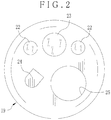
- various elements are disposed on an end surface of the tip device 19, including lighting windows 22, a viewing window 23, a nozzle spout 24 for washing fluid, and a distal instrument opening 25.
- the lighting windows 22 apply illumination light to an object of interest.
- the viewing window 23 receives image light from the object of interest.
- the nozzle spout 24 supplies air or water to clean up the viewing window 23.
- the distal instrument opening 25 is used to protrude a medical instrument such as a forceps, electrocautery device and the like for treatment of various types.
- An image sensor 56 and an objective lens 60 are disposed behind the viewing window 23. See Fig. 3 .
- the steering device 20 is constituted by a plurality of link elements connected serially. Steering wheels 26 are disposed on the grip handle 17, and rotated to bend the steering device 20 up and down and to the right and left.
- the tip device 19 is directed in a desired direction by steering of the steering device 20.
- the flexible device 21 is flexible for entry in a body cavity of a tortuous shape, for example, esophagus or intestines in a gastrointestinal tract.
- a communication cable, a light guide device 55 and the like are extended through the elongated tube 16 as illustrated in Fig. 3 .
- the communication cable transmits a drive signal for driving the image sensor 56, and an image signal output by the image sensor 56.
- the light guide device 55 transmits light from the light source apparatus 13 to the lighting windows 22.
- the grip handle 17 includes a proximal instrument opening 27, fluid supply buttons 28 and a release button (not shown) in addition to the steering wheels 26.
- the proximal instrument opening 27 receives entry of a medical instrument for treatment.
- the fluid supply buttons 28 are depressed for supplying air or water through the nozzle spout 24.
- the release button is depressible for forming a still image.
- a tube for the universal cable 18 contains the communication cable, the light guide device 55 and the like extending from the elongated tube 16.
- a composite connector 29 is disposed at a proximal end of the universal cable 18 on a side of the processing apparatus 12 and the light source apparatus 13.
- the composite connector 29 includes a cable connector plug 29a and a light source connector plug 29b. Those are coupled to respectively the processing apparatus 12 and the light source apparatus 13 in a removable manner.
- a proximal end of the communication cable is contained in the cable connector plug 29a.
- An entrance end 55a of the light guide device 55 of Fig. 3 is contained in the light source connector plug 29b.
- the light source apparatus 13 includes a light source unit 40, a path coupler 41 and a light source controller 42.
- the light source unit 40 includes a blue light source 35, a fluorescent type of green light source 36 and a red light source 37 as semiconductor light sources.
- the path coupler 41 couples light paths of the B, G and R light sources 35-37 together.
- the light source controller 42 controls the B, G and R light sources 35-37.
- the blue light source 35 includes a blue LED 43 (light emitting diode) for emitting light of a blue wavelength range.
- the red light source 37 includes a red LED 45 (light emitting diode) for emitting light of a red wavelength range.
- the green light source 36 includes a blue excitation light source device 44 or light source LED (light emitting diode), and green emitting phosphor 47.
- the blue excitation light source device 44 emits blue excitation light of a violet to blue wavelength range.
- the green emitting phosphor 47 is excited by the blue excitation light, and emits green fluorescence of a green wavelength range.
- Each of the LEDs 43-45 has a p-type semiconductor and an n-type semiconductor attached together as is well-known in the art. Upon application of voltage, recombination of a positive hole and an electron occurs across the band gap at the p-n junction, for a current to flow. Light is emitted by generation of energy according to the band gap. A light amount emitted by the LEDs 43-45 is increased by an increase in supplied power. In the green light source 36 as a combination of the blue excitation light source device 44 and the green emitting phosphor 47, a light amount of the green fluorescence is increased by an increase in a light amount of the blue excitation light from the blue excitation light source device 44.
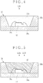
- the blue light source 35 includes a semiconductor substrate 35a or semiconductor die, a cavity mold 35b and resin encapsulant 35c.
- the blue LED 43 is mounted on the semiconductor substrate 35a.
- the cavity mold 35b is formed in the semiconductor substrate 35a, and has a cavity for containing the blue LED 43.
- the resin encapsulant 35c is filled in the cavity for encapsulation.
- An inner surface of the cavity is a reflector for reflecting light.
- Light diffusing material is mixed with and dispersed in the semiconductor substrate 35a for diffusing light.
- An LED wire 35d extends from the blue LED 43 to the semiconductor substrate 35a for connection with conductivity.
- this type of mounting of the blue light source 35 is referred to as a surface mounting type. Note that, in the red light source 37, the structure of the blue light source 35 is repeated. Details of the red light source 37 are not described herein.
- the green light source 36 of the fluorescent type includes a semiconductor substrate 36a or semiconductor die, and a cavity mold 36b, and is packaged with the blue excitation light source device 44 in the surface mounting type, in a manner similar to the blue and red light sources 35 and 37.
- the green light source 36 is different from the blue and red light sources 35 and 37 in that the green emitting phosphor 47 is contained in the cavity of the cavity mold 36b.
- the green emitting phosphor 47 in the blue excitation light source device 44 is dispersed in resin encapsulant, and includes dispersed materials such as phosphor, light diffusing material and the like.
- An LED wire 36d is disposed to connect the semiconductor substrate 36a to the blue excitation light source device 44.
- the blue LED 43 emits blue light LB of which a wavelength range is 390-445 nm of violet to blue colors, and a peak wavelength is 430 plus or minus 10 nm.
- the red LED 45 emits red light LR of which a wavelength range is 615-635 nm of a red color, and a peak wavelength is 620 plus or minus 10 nm.
- the green light source 36 emits mixed light (LBe+LGf) of blue excitation light LBe from the blue excitation light source device 44 and green fluorescence LGf emitted by the green emitting phosphor 47 excited by the blue excitation light LBe.
- the blue excitation light LBe has a violet to blue wavelength range of 420-440 nm and a peak wavelength of 430 plus or minus 10 nm.
- the green fluorescence LGf has a green wavelength range of 500-600 nm and a peak wavelength of 520 plus or minus 10 nm.
- the peak wavelength of the blue excitation light LBe is equal to that of the blue light LB emitted by the blue light source 35.
- the wavelength range of the blue excitation light LBe is overlapped with that of the blue light LB. See Fig. 19 .
- the green emitting phosphor 47 absorbs a large part of the blue excitation light LBe to emit the green fluorescence LGf. A remaining part of the blue excitation light LBe passes the green emitting phosphor 47 without absorption.
- a spectrum of light emitted by the green light source 36, as illustrated in the drawing, contains a component of the passed part of the blue excitation light LBe through the green emitting phosphor 47 and a component of the green fluorescence LGf.
- FIG. 9 an absorption spectrum of hemoglobin in blood is illustrated.
- An absorption coefficient ⁇ a has dependency to the wavelength, namely increases abruptly in a wavelength range equal to or lower than 450 nm, and comes to a peak at approximately 405 nm. Also, the absorption coefficient comes to a smaller peak at a wavelength of 530-560 nm.
- an image with a difference in the contrast between blood vessels and other tissue can be obtained, because the light is largely absorbed by the blood vessels.
- a scattering characteristic of body tissue to light also has dependency to the wavelength.
- a scattering coefficient ⁇ S increases according to smallness of the wavelength.
- the scattering influences a depth of penetration of light into the body tissue.
- An amount of light reflected in the vicinity of the epithelium (mucosa surface) of the body tissue is high according to highness of the scattering, so as to decrease an amount of light reaching a portion of a medium depth or large depth (lamina muscularis mucosae). Accordingly, the depth of penetration decreases according to the smallness of the wavelength, and increases according to greatness of the wavelength.
- a wavelength of light for the vessel enhancement is selected according to the absorption characteristic of hemoglobin and scattering characteristic of body tissue to light.
- the blue light LB with the peak wavelength of 430 plus or minus 10 nm from the blue LED 43 has a relatively small depth of penetration with a relatively short wavelength. Absorption of the blue light LB in surface blood vessels is large. Thus, the blue light LB is used for enhancement of surface blood vessels. It is possible to obtain a vessel enhancement image in which surface blood vessels are expressed with high contrast by use of the blue light LB. Also, green fluorescence LGf with the peak wavelength of 520 plus or minus 10 nm is used for enhancement of subsurface or deep blood vessels. In Fig. 9 for the absorption spectrum, the absorption coefficient changes gradually in a green wavelength range of 530-560 nm in comparison with a blue wavelength range equal to or less than 450 nm.
- a green image signal after color separation with a micro color filter of green in the image sensor 56 is used for enhancement of the subsurface or deep blood vessels, as will be described later.
- drivers 50, 51 and 52 are connected to respectively the LEDs 43-45.
- the light source controller 42 controls the drivers 50-52 to turn on and off the LEDs 43-45 and adjust their light amounts. According to an exposure control signal from the processing apparatus 12, the light source controller 42 adjusts the light amounts by changing power supplied to the LEDs 43-45.
- the drivers 50-52 are controlled by the light source controller 42, and turn on respectively the LEDs 43-45 by application of drive currents. In response to the exposure control signal from the processing apparatus 12, the drivers 50-52 change the current values to adjust power for the LEDs 43-45, so that light amounts of the blue light LB, green fluorescence LGf and red light LR are controlled. Control of the light amount of the green fluorescence LGf is performed by controlling a light amount of the blue excitation light LBe from the blue excitation light source device 44. In case an operator wishes an increase of the light amount of the green fluorescence LGf, the current value from the driver 51 to the blue excitation light source device 44 is increased to increase the light amount of the blue excitation light LBe.
- various methods of supplying a drive current can be used, such as controls of PAM (pulse amplitude modulation) and PWM (pulse width modulation).
- PAM pulse amplitude modulation
- PWM pulse width modulation
- the path coupler 41 couples light paths of light from the B, G and R light sources 35-37 together into one light path.
- a distal end of the path coupler 41 is disposed near to the receptacle connector 54.
- the path coupler 41 receives the light from the B, G and R light sources 35-37 and outputs the light toward the entrance end 55a of the light guide device 55 in the endoscope 11.
- Protectors (not shown) of glass are associated with respectively the light source connector plug 29b and the receptacle connector 54.
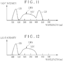
- a spectrum of mixed light of the blue light LB, green fluorescence LGf and red light LR from the B, G and R light sources 35-37 at a point downstream of the path coupler 41 is illustrated.
- the mixed light is white light with the continuous spectrum fully extending in a visible light range, and used as illumination light LW0 in the normal imaging mode.
- illumination light LW1 is applied to an object of interest as mixed light of the blue light LB and green fluorescence LGf. See Fig. 12 .
- a second dichroic mirror 80 of Fig. 18 cuts off the blue excitation light LBe, so that no component of the blue excitation light LBe is contained in a spectrum of the illumination light LW0 and LW1.
- Spectra of the illumination light LW0 and LW1 in Figs. 11 and 12 are only examples .
- Spectra of the illumination light LW0 and LW1 can be changed suitably as target according to color balance of a display image or the like. For example, a ratio between light amounts of the blue light LB, green fluorescence LGf and red light LR (ratio between current values of drive currents for the LEDs 43-45) is adjusted to produce the illumination light LW0 and LW1 with a spectrum of the target.
- the light source controller 42 controls the exposure of the light of illumination by maintaining the spectrum of light emission as a target. Should a ratio of light amounts of the colors be changed within the light of illumination, color balance of a display image may change with a change in the spectrum of the light emission. Thus, the light source controller 42 discretely changes a current value of driving the LEDs 43-45 by controlling the drivers 50-52, to increase or decrease the light amounts of the colors.
- the light source controller 42 changes the spectrum of light between the normal imaging mode and the vessel enhancement imaging mode. For example, the light source controller 42 sets the ratio of the light amount of the blue light LB higher in the vessel enhancement imaging mode than in the normal imaging mode, so as to use the blue light LB with higher importance than the green fluorescence LGf.
- the endoscope 11 includes the light guide device 55, the image sensor 56, an analog processing unit 57 or analog front end (AFE), and an imaging control unit 58.
- the light guide device 55 is a fiber bundle constituted by bundling plural optical fibers.
- the entrance end 55a of the light guide device 55 in the light source connector plug 29b is aligned with an exit end of the path coupler 41.
- a distal exit end of the light guide device 55 inside the tip device 19 has two branches for transmitting light to the lighting windows 22.
- a lighting lens 59 is disposed behind each of the lighting windows 22. Illumination light from the light source apparatus 13 is guided by the light guide device 55 to the lighting lens 59, and applied through the lighting windows 22 to an object of interest.
- the lighting lens 59 is a concave lens and enlarges a divergence angle of light from the light guide device 55. The illumination light can be applied to a wide area in a body cavity with the object of interest.
- the objective lens 60 and the image sensor 56 are disposed behind the viewing window 23. Image light from the object of interest enters the objective lens 60 through the viewing window 23, and is focused on an imaging surface 56a of the image sensor 56 by the objective lens 60.
- Examples of the image sensor 56 are a CCD image sensor and CMOS image sensor.
- a plurality of photoconductive elements or photoconductors are arranged as pixels of arrays on the imaging surface 56a, for example, photo diodes.
- the image sensor 56 photoelectrically converts light received by the imaging surface 56a, and stores signal charge according to light amounts of light received by the pixels. The signal charge is converted by an amplifier into a voltage signal, which is read out. The voltage signal is transmitted by the image sensor 56 to the analog processing unit 57 as an image signal.
- the analog processing unit 57 is constituted by a correlated double sampler (CDS), auto gain controller (AGC) and A/D converter (all not shown).
- CDS correlated double sampler
- AGC auto gain controller
- A/D converter converts the amplified image signal from the auto gain controller into a digital image signal having a gradation value according to a predetermined bit number, and sends the digital image signal to the processing apparatus 12.
- a controller 65 in the processing apparatus 12 is connected with the imaging control unit 58, which supplies the image sensor 56 with a drive signal according to a clock signal from the controller 65 as a reference.
- the image sensor 56 generates an image signal at a predetermined frame rate according to the drive signal from the imaging control unit 58, and sends the image signal to the analog processing unit 57.
- the image sensor 56 is a color image sensor.
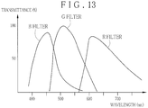
- the imaging surface 56a of the image sensor 56 has a great number of micro color filters of blue, green and red with spectral characteristics in Fig. 13 in correspondence with pixels.
- An example of arrangement of the micro color filters is a Bayer arrangement.
- the B pixels with the B filters are sensitive to light of a wavelength of approximately 380-560 nm.
- the G pixels with the G filters are sensitive to light of a wavelength of approximately 450-630 nm.
- the R pixels with the R filters are sensitive to light of a wavelength of approximately 580-800 nm.
- Reflected light corresponding to the blue light LB is mainly received by the B pixels.
- Reflected light corresponding to the green fluorescence LGf is mainly received by the G pixels.
- Reflected light corresponding to the red light LR is mainly received by the R pixels .
- the blue excitation light LBe does not travel to the object of interest because cut off by the second dichroic mirror 80. Assuming that the blue excitation light LBe illuminates the object, reflected light from the object is sensed by the B pixels.
- the image sensor 56 operates for the storing and readout in a period of acquiring one frame, and in the storing, stores signal charge in pixels, and in the readout, reads out the stored signal charge.
- the B, G and R light sources 35-37 in the normal imaging mode are turned on according to a time point of the storing of the image sensor 56, to apply the illumination light LW0 (LB+LGf+LR) to an object of interest, the illumination light LW0 being mixture of the blue light LB, green fluorescence LGf and red light LR.
- Object light or reflected light becomes incident upon the image sensor 56.
- the image sensor 56 separates the reflected light of the illumination light LW0 with the micro color filter.
- Blue pixels receive reflected light derived from the blue light LB.
- Green pixels receive reflected light derived from the green fluorescence LGf.
- Red pixels receive reflected light derived from the red light LR.
- the image sensor 56 sequentially outputs image signals B, G and R of one frame according to pixel values of the blue, green and red pixels at a time point of the readout and with the frame rate. The imaging sequence is repeated while the normal imaging mode is set.
- the blue and green light sources 35 and 36 in the vessel enhancement imaging mode are turned on according to a time point of the storing of the image sensor 56, to apply illumination light LW1 (LB+LGf) to the object of interest, the illumination light LW1 being mixture of the blue light LB and green fluorescence LGf.
- the illumination light LW1 is separated by the micro color filters in the image sensor 56 in a manner similar to the normal imaging mode.
- the B and G pixels receive reflected light derived from the blue light LB and from the green fluorescence LGf in a manner similar to the normal imaging mode.
- the image sensor 56 outputs image signals B, G and R sequentially in a sequence of readout in the vessel enhancement imaging mode. Those steps of the imaging are repeated while the vessel enhancement imaging mode is set.
- the processing apparatus 12 includes a digital signal processor 66 (DSP), an image processing unit 67, a frame memory 68 and a display control unit 69 together with the controller 65.
- the controller 65 has a CPU with a ROM and a RAM.
- the ROM stores control programs and control data.
- the RAM is a working memory for loading of the control programs.
- the CPU runs the control programs to control various elements in the processing apparatus 12.
- the digital signal processor 66 acquires an image signal output by the image sensor 56.
- the digital signal processor 66 separates the image signal of the mixture for blue, green and red pixels into image signals of blue, green and red.
- the image signals of the colors are interpolated in the operation of pixel interpolation.
- the digital signal processor 66 performs signal processing of various functions, such as gamma correction, white balance correction and the like for the image signals of blue, green and red.
- the digital signal processor 66 determines an exposure amount according to the image signals B, G and R. Should the exposure amount of the entirety of the image be too low (underexposure), the digital signal processor 66 outputs a control signal to the controller 65 to raise the light amount of the illumination light. Should the exposure amount of the entirety of the image be too high (overexposure), the digital signal processor 66 outputs a control signal to the controller 65 to lower the light amount of the illumination light. The controller 65 sends the control signal to the light source controller 42 of the light source apparatus 13.
- the frame memory 68 stores image data output by the digital signal processor 66, processed image data from the image processing unit 67, and the like.
- the display control unit 69 reads out the processed image data from the frame memory 68, converts this into a video signal such as a composite signal, component signal or the like, which is output to the display panel 14.
- the image processing unit 67 in the normal imaging mode generates a normal image according to the image signals B, G and R after color separation by the digital signal processor 66.
- the normal image is output to the display panel 14.
- the image processing unit 67 updates the normal image at each time that the image signals B, G and R in the frame memory 68 are updated.
- the image processing unit 67 generates a vessel enhancement image according to image signals B and G in the vessel enhancement imaging mode.
- the image signal B in the vessel enhancement imaging mode includes a component of reflected light derived from the blue light LB having a wavelength of 390-445 nm and a peak wavelength of 430 plus or minus 10 nm.
- the surface blood vessels can be expressed at a high contrast. It is medically known that there is a characteristic pattern of the particular surface blood vessels in body tissue of a cancer, malignant tumor or other lesions, because higher vessel density of the particular surface blood vessels is found than normal body tissue. It is preferable to express the particular surface blood vessels distinctly with advantages for the diagnosis of a benign or malignant tumor.
- an area of the surface blood vessels within the endoscopic image is combined with the image signal G, to produce a vessel enhancement image.
- an area of subsurface or deep blood vessels can be processed in the edge enhancement in addition to the surface blood vessels.
- an area of the subsurface or deep blood vessels is extracted from the image signal G containing much information of the subsurface or deep blood vessels, and is processed in the edge enhancement.
- a vessel enhancement image is produced according to the image signal G after the edge enhancement and the image signal B.
- the image processing unit 67 generates the vessel enhancement image at each time that the image signals B and G in the frame memory 68 are updated.
- the display control unit 69 allocates the image signal B to the B and G channels of the display panel 14, and the image signal G to the R channel of the display panel 14, and drives the display panel 14 to display the vessel enhancement image in a form of pseudo color.
- the path coupler 41 includes collimator lenses 75, 76 and 77, a first dichroic mirror 79, the second dichroic mirror 80 and a condenser lens 82.
- the collimator lenses 75-77 collimate light of the colors from respectively the B, G and R light sources 35-37.
- the condenser lens 82 condenses light from the path coupler 41 to the entrance end 55a of the light guide device 55.
- Each of the first and second dichroic mirrors 79 and 80 is optics including a transparent glass plate and a layer of a dichroic filter formed on the glass plate with a predetermined transmission characteristic.
- the green light source 36 is so disposed that its light path is aligned with an optical axis of the light guide device 55.
- the light paths of the green and red light sources 36 and 37 are perpendicular with one another.
- the first dichroic mirror 79 is positioned at a point of the intersection between the light paths of the green and red light sources 36 and 37.
- the light paths of the blue and green light sources 35 and 36 are perpendicular with one another.
- the second dichroic mirror 80 is positioned at a point of the intersection between the light paths of the blue and green light sources 35 and 36.
- the first dichroic mirror 79 is oriented with an inclination of 45 degrees with respect to the light paths of the green and red light sources 36 and 37.
- the second dichroic mirror 80 is oriented with an inclination of 45 degrees with respect to the light paths of the blue and green light sources 35 and 36.
- the dichroic filter of the first dichroic mirror 79 has a transmission characteristic of reflecting light of a red wavelength range equal to or more than approximately 600 nm and passing light of a blue to green wavelength range less than the same.
- the first dichroic mirror 79 passes the mixed light of the blue excitation light LBe and green fluorescence LGf from the green light source 36 through the collimator lens 76, and reflects the red light LR from the red light source 37 through the collimator lens 77.
- a light path of the mixed light of the blue excitation light LBe and green fluorescence LGf is combined with that of the red light LR for coupling.
- a dichroic filter in the second dichroic mirror 80 has a transmission characteristic of cutting off at least the blue excitation light LBe from a spectrum of mixed light of the blue excitation light LBe and green fluorescence LGf downstream of the green light source 36 as illustrated in Fig. 8 .
- the dichroic filter in the second dichroic mirror 80 operates as an excitation light cut-off filter (wavelength cut-off filter component) for cutting off the blue excitation light LBe.
- the dichroic filter of the second dichroic mirror 80 has a transmission characteristic of reflecting light of a violet to blue wavelength range less than approximately 460 nm and passing light of a green to red wavelength range more than the same.
- the second dichroic mirror 80 reflects the blue excitation light LBe in the mixed light of the blue excitation light LBe and green fluorescence LGf downstream of the first dichroic mirror 79, and passes the green fluorescence LGf.
- the second dichroic mirror 80 passes the red light LR reflected by the first dichroic mirror 79, and reflects the blue light LB from the blue light source 35 through the collimator lens 75.
- the second dichroic mirror 80 couples light paths of the blue excitation light LBe, green fluorescence LGf and red light LR together. Note that the blue excitation light LBe does not enter the entrance end 55a of the light guide device 55, and is prevented from illuminating an object of interest.
- the endoscope 11 is connected to the processing apparatus 12 and the light source apparatus 13.
- a power source for the processing apparatus 12 and the light source apparatus 13 is turned on to start up the endoscope system 10.
- the elongated tube 16 of the endoscope 11 is entered in the gastrointestinal tract of the patient to start imaging.
- the B, G and R light sources 35-37 are turned on.
- the light source controller 42 sets current values for driving the LEDs 43-45 at a level suitable for the normal imaging mode, and starts driving the B, G and R light sources 35-37.
- the light source controller 42 controls light amounts by maintaining a spectrum of emission for a target.
- the LEDs 43 and 45 emit blue light LB and red light LR.
- the green light source 36 of the fluorescent type emits mixed light of the blue excitation light LBe from the blue excitation light source device 44 and the green fluorescence LGf from the green emitting phosphor 47 upon excitation with the blue excitation light LBe.
- the components of the light enter the collimator lenses 75-77 in the path coupler 41.
- the red light LR is reflected by the first dichroic mirror 79 and passed through the second dichroic mirror 80.
- the mixed light of the blue excitation light LBe and green fluorescence LGf is passed through the first dichroic mirror 79.
- the blue excitation light LBe is reflected by the second dichroic mirror 80.
- the green fluorescence LGf is passed through the second dichroic mirror 80.
- the first dichroic mirror 79 couples light paths of the red light LR, the blue excitation light LBe and the green fluorescence LGf in mixture.
- the second dichroic mirror 80 cuts off the blue excitation light LBe.
- the dichroic filter in the second dichroic mirror 80 operates as an excitation light cut-off filter (wavelength cut-off filter component), so that the optical system of the path coupler 41 can be constructed with simplicity.
- the blue light LB is reflected by the second dichroic mirror 80.
- the second dichroic mirror 80 couples the paths of the blue light LB, green fluorescence LGf and red light LR together.
- the light components of the blue light LB, green fluorescence LGf and red light LR become incident upon the condenser lens 82.
- illumination light LW0 is produced from the combination of the blue light LB, green fluorescence LGf and red light LR.
- the condenser lens 82 condenses the illumination light LW0 at the entrance end 55a of the light guide device 55 of the endoscope 11, and supplies the endoscope 11 with the illumination light LW0.
- the illumination light LW0 is guided through the light guide device 55 to the lighting windows 22, and applied to an object of interest. Reflected light of the illumination light LW0 from the object of interest becomes incident upon the image sensor 56 through the viewing window 23.
- the image sensor 56 outputs image signals B, G and R to the digital signal processor 66 of the processing apparatus 12.
- the digital signal processor 66 separates the image signals B, G and R by color separation, and inputs those to the image processing unit 67. Imaging of the image sensor 56 is repeated at a predetermined frame rate.
- the image processing unit 67 generates a normal image according to the image signals B, G and R.
- the display control unit 69 outputs the normal image to the display panel 14. Also, the normal image is updated according to the frame rate of the image sensor 56.
- the digital signal processor 66 obtains an exposure amount according to the image signals B, G and R, and transmits an exposure control signal to the light source controller 42 of the light source apparatus 13 according to the obtained exposure amount.
- the light source controller 42 acquires current values of driving the B, G and R light sources 35-37 according to the exposure control signal so as to keep a constant ratio between the light amounts of the colors (or not to change the spectrum of the light emission of a target) .
- the B, G and R light sources 35-37 are driven according to the acquired current values. It is therefore possible to keep the light amounts of the blue light LB, green fluorescence LGf and red light LR from the B, G and R light sources 35-37 at the constant ratio suitable for the normal imaging mode.
- the light amount of blue excitation light LBe from the blue excitation light source device 44 is changed.
- a wavelength range of the blue excitation light LBe overlaps on that of the blue light LB.
- a light amount of the blue light LB is also changed by a change in that of the blue excitation light LBe.
- the spectrum of the light is changed.
- the second dichroic mirror 80 cuts off the blue excitation light LBe, so that the light amount of the blue light LB is controlled discretely from the green fluorescence LGf without influence of the blue excitation light LBe to the light amount of the blue light LB. Consequently, the endoscope 11 can be supplied with light of the spectrum appropriate for the normal imaging mode even upon performing the exposure control. No change occurs in the color balance of the normal image.
- the imaging mode is changed over to the vessel enhancement imaging mode.
- the red light source 37 is turned off, and the blue and green light sources 35 and 36 are turned on. Color light from the blue and green light sources 35 and 36 is combined to become the illumination light LW1 by the path coupler 41, and is supplied to the endoscope 11.
- the second dichroic mirror 80 cuts off the blue excitation light LBe.
- the endoscope 11 can be supplied constantly with light of a spectrum suitable for the vessel enhancement imaging mode, without change in the color balance of a vessel enhancement image.
- the image sensor 56 receives reflected light from an object of interest illuminated by the illumination light LW1, and outputs image signals B, G and R to the digital signal processor 66.
- the digital signal processor 66 separates the image signals B, G and R and inputs those to the image processing unit 67, which generates a vessel enhancement image according to the image signals B and G.
- the vessel enhancement image is output to the display panel 14. This image is updated according to the frame rate of the image sensor 56.
- the vessel enhancement image is used for diagnosing a benign or malignant tumor. Reliability in the diagnosis of a tumor can be high according to the highness in the reliability in the vessel enhancement image.
- the blue excitation light LBe with influence to the light amount of the blue light LB is cut off by the second dichroic mirror 80.
- the second dichroic mirror 80 it is possible to supply light of illumination with the spectrum of target without complicated control of adjusting the light amount of the blue light LB and the like in consideration of a change in the blue excitation light LBe with a change in the green fluorescence LGf.
- the second dichroic mirror 80 includes the dichroic filter functioning as an excitation light cut-off filter.
- a dichroic mirror separate from the second dichroic mirror 80 has a dichroic filter functioning as an excitation light cut-off filter (wavelength cut-off filter component).
- a path coupler 90 in a light source apparatus 85 includes a first dichroic mirror 91, which corresponds to the first dichroic mirror 79 of the first embodiment, and couples a light path of mixed light of the blue excitation light LBe and green fluorescence LGf from the green light source 36 with a light path of the red light LR from the red light source 37.
- a dichroic filter in the first dichroic mirror 91 operates also as an excitation light cut-off filter.
- the path coupler 41 is repeated except for having the first dichroic mirror 91 instead of the first dichroic mirror 79.
- the dichroic filter of the first dichroic mirror 91 is caused to have a characteristic of reflecting light of a red wavelength range equal to or more than approximately 600 nm and light of a violet to blue wavelength range less than approximately 460 nm, and passing other light of a green wavelength range.
- the dichroic filter comes to have the band-pass characteristic of combining transmission characteristics of the first and second dichroic mirrors 79 and 80 in the first embodiment.
- the structure of the first embodiment has an advantage in a lower cost, in that the dichroic filter in the second dichroic mirror 80 of a long pass characteristic has a function of the excitation light cut-off filter.
- a path coupler 96 has a dichroic mirror and an excitation light cut-off filter separate from the dichroic mirror.
- a wavelength cut-off filter 97 or excitation light cut-off filter (or reduction filter) is disposed between the green light source 36 and the first dichroic mirror 79.
- the wavelength cut-off filter 97 reflects light of a violet to blue wavelength range less than approximately 460 nm, and passes light of a green to red wavelength range other than the same.
- the wavelength cut-off filter 97 may be disposed between the first and second dichroic mirrors 79 and 80.
- An excitation light cut-off filter can be disposed between the blue excitation light source device 44 and the light guide device 55, and more precisely, a coupling position (intersection point) of coupling a light path of mixed light of the blue excitation light LBe and green fluorescence LGf from the green light source 36 and a light path of the blue light LB from the blue light source 35, or a position upstream from the coupling position in the light path.
- the current values for the LEDs 43-45 are controlled.
- a light amount of a semiconductor light source relative to a current value of driving may be changed by influence of various factors, including heat generated by LEDs or phosphor or degradation with time.
- measurement sensors are used for measuring light amounts of the colors, to monitor a reach of the light amounts of the colors to a target value according to an output signal from the measurement sensors.
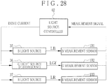
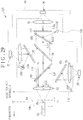
- a path coupler 100 in a light source apparatus 99 has the elements in the path coupler 41 of Fig. 18 , and also includes a blue measurement sensor 101, a green measurement sensor 102 and a red measurement sensor 103 for light amounts, and glass plates 105, 106 and 107.
- the measurement sensors 101-103 measure the light amounts of the light of the colors from the B, G and R light sources 35-37.
- the glass plates 105-107 are disposed directly downstream of respectively the B, G and R light sources 35-37, and partially reflect light from the B, G and R light sources 35-37, to guide the light toward the measurement sensors 101-103.
- the glass plates 105-107 are inclined with an angle of approximately 35 degrees with reference to the optical axes of the B, G and R light sources 35-37.
- the glass plates 105-107 pass light of the colors from the B, G and R light sources 35-37. There occurs Fresnel reflection upon incidence of the light on the glass plates 105-107.
- the glass plates 105-107 (optical path devices) guide partial light (as small as 4-8 %) included in the light from the B, G and R light sources 35-37 toward the measurement sensors 101-103 by utilizing the Fresnel reflection. Also, it is possible to use other optical path devices such as optical fibers or the like, instead of the glass plates.
- a band pass filter 109 and a long pass filter 110 are disposed upstream of respectively the measurement sensors 102 and 103.
- the band pass filter 109 at the green measurement sensor 102 converts light into light of a limited wavelength range of the green fluorescence LGf constituting the illumination light LW0 and LW1 for final supply to the endoscope 11.
- the band pass filter 109 has a transmission characteristic of reflecting light of a red wavelength range equal to or more than approximately 600 nm and light of a violet to blue wavelength range less than approximately 460 nm, and passing light of a green wavelength range other than those wavelength ranges.
- the band pass filter 109 has a band pass characteristic in combination of the transmission characteristics of the first and second dichroic mirrors 79 and 80 of the first embodiment, in a manner similar to the first dichroic mirror 91.
- the band pass filter 109 causes entry of the green fluorescence LGf to the green measurement sensor 102 after cutting off the blue excitation light LBe as a partial component of the illumination light LW0 and LW1. It is possible to measure the light amount of the green fluorescence LGf precisely.
- the long pass filter 110 at the red measurement sensor 103 converts light into light of a limited wavelength range of the red light LR constituting the light LW0 for final supply to the endoscope 11.
- the long pass filter 110 has a transmission characteristic of reflecting light of a green to blue wavelength range less than approximately 600 nm and passing light of a red wavelength range more than 600 nm.
- the transmission characteristic of the long pass filter 110 is opposite to the transmission characteristic of the first dichroic mirror 79 of the first embodiment as illustrated in Fig. 19 .
- the long pass filter 110 only the red light LR output as a part of the illumination light LW0 becomes incident upon the red measurement sensor 103.
- a light amount of the red light LR can be measured with precision.
- the measurement sensors 101-103 receive light of the colors guided by the glass plates 105-107 of the Fresnel reflection, and output measurement signals to the light source controller 42 according to light amounts of the colors .
- the light source controller 42 compares each of the measurement signals to a reference signal of a target light amount, and finely adjusts the current values of the drive currents for the B, G and R light sources 35-37 according to the exposure control to set the light amounts equal to the target light amount according to the comparison. This is effective in constantly controlling the light amounts by monitoring with the measurement sensors 101-103 and the fine adjustment of the current values.
- the light of a spectrum of the target can be obtained with high stability.
- a path coupler 116 has a wavelength cut-off filter 117 or excitation light cut-off filter (or reduction filter) at a plate shape disposed between the green light source 36 and the first dichroic mirror 79 (the position of the wavelength cut-off filter 97 of the third embodiment in Fig. 23 ) with the same transmission characteristic as the band pass filter 109.
- the band pass filter 109 there is a shortcoming in that a size of the wavelength cut-off filter 117 is larger than the band pass filter 109.
- the use of the band pass filter 109 is advantageous in view of reducing a cost and saving a space in comparison with the wavelength cut-off filter 117.
- the measurement sensors are used for all of the semiconductor light sources. However, it is possible only to use the measurement sensor for the green light source 36, but not to use measurement sensors for the remaining semiconductor light sources, as a change in the light amount relative to the current value is remarkably large in the green light source 36.
- the measurement sensors 101-103 measure light amounts downstream of the collimator lenses 75-77.
- the light amounts may be measured between the collimator lenses 75-77 and the B, G and R light sources 35-37 by use of the measurement sensors 101-103.
- Components of the light of the colors are diffused light, so that the measurement sensors 101-103 can directly measure the light amounts from the B, G and R light sources 35-37.
- the blue light source 35 in the above embodiments is a single device with its wavelength range and peak wavelength.
- Another preferred embodiment has a plurality of blue light sources of which the wavelength range and peak wavelength are different from one another. Those light sources are used in a distinct manner from one another by considering a state of surface blood vessels.
- a light source apparatus 120 includes a light source unit 123 and a path coupler 124.
- the light source apparatus 120 has the green and red light sources 36 and 37, and also a first blue light source 121 and a second blue light source 122 of a semiconductor.
- the path coupler 124 couples light paths from the blue and green light sources 35 and 36 and the blue light sources 121 and 122.
- the first blue light source 121 is present in place of the blue light source 35 of the above embodiments. For remaining parts, the first embodiment is repeated. Elements similar to those of the above embodiments are designated with identical reference numerals.
- the first blue light source 121 emits first blue light LB1 having a component of 400-470 nm as a blue wavelength range, and a peak wavelength of 460 plus or minus 10 nm.
- the second blue light source 122 emits second blue light LB2 having a component of 395-415 nm as a violet to blue wavelength range, and a peak wavelength of 405 plus or minus 10 nm.
- the path coupler 124 includes the path coupler 41, a collimator lens 125 and a third dichroic mirror 126.
- the collimator lens 125 collimates the second blue light LB2 from the second blue light source 122.
- the collimator lens 125 couples light paths of the first blue light LB1 from the first blue light source 121 and the second blue light LB2 from the second blue light source 122.
- the path coupler 124 combines the light paths of the first and second blue light LB1 and LB2, green fluorescence LGf and red light LR to form one light path.
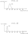
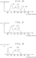
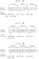
- Fig. 33 a spectrum of the mixed light of the first blue light LB1, green fluorescence LGf and red light LR downstream of the path coupler 124 is illustrated.
- the mixed light is used as the illumination light LW2 in the embodiment for the normal imaging mode.
- a spectrum of mixed light of the first blue light LB1 and green fluorescence LGf is illustrated.
- a spectrum of mixed light of the second blue light LB2 and green fluorescence LGf is illustrated.
- the illumination light LW3 and LW4 is utilized in the present embodiment for the vessel enhancement imaging mode by way of the mixed light in Figs. 34 and 35 .
- the blue light sources 121 and 122 are so disposed that their light paths extend perpendicularly with one another.
- the third dichroic mirror 126 is positioned at a point of the intersection of those light paths.
- the third dichroic mirror 126 is oriented with an inclination of 45 degrees with reference to the blue light sources 121 and 122.
- the dichroic filter of the third dichroic mirror 126 has a transmission characteristic of reflecting light of a violet wavelength range less than approximately 430 nm and passing light of a blue, green and red wavelength range more than the same.
- the third dichroic mirror 126 passes the first blue light LB1 from the first blue light source 121 through the collimator lens 75, and reflects the second blue light LB2 from the second blue light source 122 through the collimator lens 125.
- the second dichroic mirror 80 has a transmission characteristic of reflecting light of a blue wavelength range less than approximately 460 nm.
- the second blue light LB2 reflected by the third dichroic mirror 126 is reflected by the second dichroic mirror 80 and directed to the condenser lens 82. Consequently, all of the light paths of the blue light LB1 and LB2, green fluorescence LGf and red light LR are coupled together.
- the absorption coefficient ⁇ a of hemoglobin in blood comes to the peak at approximately 405 nm, as has been described with Fig. 9 .
- Light applied to an object of interest has a small depth of penetration according to smallness of the wavelength. See Fig. 10 .
- the first blue light LB1 from the first blue light source 121 with the central wavelength of 460 plus or minus 10 nm has a relatively large depth of penetration with a relatively large wavelength, and is absorbed in mucosal blood vessels (medium deep) disposed at a lamina intestinal of the mucosa more than in surface blood vessels as a target of the above embodiment.
- the first blue light LB1 is used as special light for enhancement of the mucosal blood vessels.
- the second blue light LB2 from the second blue light source 122 with the central wavelength of 405 plus or minus 10 nm has a relatively small depth of penetration with a relatively small wavelength, and is absorbed in subsurface blood vessels disposed at an epithelium (mucosa surface) .
- the second blue light LB2 is used as special light for enhancement of the subsurface blood vessels.
- the blue light sources 121 and 122 are switched on and off selectively to use the blue light LB1 and LB2, so that a vessel enhancement image can be obtained with high contrast of the mucosal blood vessels or the subsurface blood vessels.
- the green and red light sources 36 and 37 and the first blue light source 121 in the normal imaging mode are turned on according to a time point of the storing of the image sensor 56, to apply the illumination light LW2 (LB1+LGf+LR) to an object of interest, the illumination light LW2 being mixture of the first blue light LB1, green fluorescence LGf and red light LR.
- the illumination light LW2 being mixture of the first blue light LB1, green fluorescence LGf and red light LR.
- the green light source 36 and the first blue light source 121 in the vessel enhancement imaging of mucosal blood vessels are turned on according to a time point of the storing of the image sensor 56, to apply the illumination light LW3 (LB1+LGf) to an object of interest, the illumination light LW3 being mixture of the first blue light LB1 and green fluorescence LGf.
- the green light source 36 and the second blue light source 122 in the vessel enhancement imaging of subsurface blood vessels are turned on according to a time point of the storing of the image sensor 56, to apply the illumination light LW4 (LB2+LGf) to an object of interest, the illumination light LW4 being mixture of the second blue light LB2 and green fluorescence LGf.
- Each component of the light LW2-LW4 is separated by the micro color filters in the image sensor 56.
- Reflected light corresponding to the blue light LB1 and LB2 is mainly received by the B pixels.
- Reflected light corresponding to the green fluorescence LGf is mainly received by the G pixels.
- Reflected light corresponding to the red light LR is mainly received by the R pixels.
- the image sensor 56 sequentially outputs the image signals B, G and R at the frame rate according to a time point of the readout.
- the image signal B contains a component of reflected light corresponding to the first or second blue light LB1 or LB2, so that mucosal blood vessels (medium deep) or subsurface blood vessels can be expressed with high contrast.
- vessel density between the mucosal blood vessels or subsurface blood vessels is likely to be higher in a lesion of a cancer or the like than that in normal body tissue.
- the feature of the light source apparatus 120 in the embodiment is effective in clearly expressing the mucosal blood vessels or subsurface blood vessels with a specifically patterned form in the mucosal blood vessels or subsurface blood vessels.
- the peak wavelengths of blue light are 430, 405 and 460 nm.
- a peak wavelength of blue light from a blue light source can be 415 nm.
- the wavelengths 405, 415 and 430 nm are characterized in that the absorption coefficient ⁇ a of hemoglobin in blood is high in the absorption spectrum of the hemoglobin in blood in Fig. 9 . Therefore, a vessel enhancement image can be obtained with enhanced contrast between blood vessels and other tissue. Should a balance of the spectrum of light for the vessel enhancement imaging be lost in use of the blue excitation light LBe from the green light source 36, serious influence occurs to the imaging due to changes in color balance of the vessel enhancement image.
- the wavelength cut-off filter 97 of the third embodiment or the wavelength cut-off filter 117 of the fourth embodiment can have the transmission characteristic as depicted.
- This is a narrow band filter of green with a band pass characteristic of reflecting light of a green and red wavelength range equal to or more than approximately 550 nm and light of a green and blue wavelength range less than approximately 530 nm, and passing other light of a green wavelength range.
- the excitation light cut-off filter of this transmission characteristic can cut off the blue excitation light LBe and obtain light of a wavelength range of 530-550 nm included in the green fluorescence LGf, so that contrast of subsurface or deep blood vessels in the display image can be enhanced.
- a filter moving mechanism is disposed for moving the excitation light cut-off filter between an active position in a light path of the green light source 36 and an inactive position set out of the light path of the green light source 36.
- the excitation light cut-off filter In the normal imaging mode, the excitation light cut-off filter is shifted to the inactive position. In the vessel enhancement imaging mode, the excitation light cut-off filter is shifted to the active position.
- the mounting method of the LEDs in the invention is not limited to the first embodiment.
- a micro lens can be disposed on an exit surface of the resin encapsulant 35c or the green emitting phosphor 47 in Figs. 4 and 5 for adjusting an angle of divergence.
- a housing of a bullet shape including a micro lens can be used for containing an LED in place of the surface mounting type.
- the green emitting phosphor 47 and the blue excitation light source device 44 are both mounted on the semiconductor substrate 36a by way of the green light source 36.
- the green emitting phosphor 47 can be separate from the semiconductor substrate 36a.
- guiding optics such as a lens or fiber optics can be added between the blue excitation light source device 44 and the green emitting phosphor 47, to guide excitation light from the blue excitation light source device 44 to the green emitting phosphor 47.
- another preferred light source apparatus includes a blue excitation light source device or light source LD 131 (light source laser diode), in place of the LED.
- a fluorescent type of green light source 130 of a semiconductor includes the light source LD 131 and green emitting phosphor 132 disposed downstream of the light source LD 131. The green light source 130 is used in place of the green light source 36 of the above embodiments.
- a transparent rotatable disk 133 is prepared.
- a coating is applied to a surface of the rotatable disk 133 to form the green emitting phosphor 132.
- a rotating mechanism 134 with a motor and the like rotates the rotatable disk 133.
- Blue excitation light from the light source LD 131 is applied to a point that is disposed eccentrically on the rotatable disk 133.
- Rotation of the rotatable disk 133 can prevent the excitation light from concentrating at one point on the green emitting phosphor 132. Should excitation light concentrate at one point on the green emitting phosphor 132, the point of the green emitting phosphor 132 will be overheated to quicken degradation of the green emitting phosphor 132.
- the feature of the embodiment can prevent such a difficulty.
- a condenser lens 135 condenses the blue excitation light from the light source LD 131 on the rotatable disk 133.
- an excitation light cut-off filter (wavelength cut-off filter component) may be formed on an exit surface of the rotatable disk 133. It is possible to use an organic electro luminescence device (EL device) and the like may be used instead of the LEDs and LDs. Furthermore, the blue and red light sources 35 and 37 and the like other than the light source of a type with green emitting phosphor can be constituted by an LD, organic EL device and the like.
- excitation light cut-off filter for cutting all of the excitation light is used in the above embodiments.
- An excitation light cut-off filter (wavelength cut-off filter component) according to the invention can be an element with a transmission characteristic for reducing a light amount of the excitation light, for example, reducing the light amount by 50 %.
- the path coupler of the invention is not limited to the above embodiments. It is possible to use a dichroic prism including a prism and a dichroic filter formed thereon in place of the dichroic mirror.
- a light guide device of a branch form having plural entrance ends for light sources and one exit end directed to the entrance end of the light guide device of the endoscope, in place of the optics having the dichroic filter.
- the light guide device of the branch form is a fiber bundle of plural optical fibers. Proximal ends of the optical fibers are grouped at a predetermined number of fibers to form the plural entrance ends.
- Light sources of a semiconductor are disposed upstream of respectively the entrance ends.
- An excitation light cut-off filter is disposed between the fluorescent type of green light source and one of the entrance ends.
- the image sensor is the color image sensor.
- an image sensor in an endoscope system of the invention may be a monochromatic image sensor.
- the lighting control is the simultaneous lighting (with normal white light), with which the color image sensor acquires image signals of B, G and R simultaneously.
- a lighting control in a light source apparatus can be field sequential lighting, in which blue, green and red light components are applied to an object of interest one after another, for a monochromatic image sensor to acquire image signals of B, G and R sequentially.
- Fig. 42 the field sequential lighting is illustrated.
- the blue and green light sources 35 and 36 are turned on and off alternately according to time points of the storing of the image sensor.
- the blue light LB and the green fluorescence LGf are applied to an object of interest alternately.
- the image processor produces a vessel enhancement image of one frame according to image signals of two consecutive frames.
- the lighting control in the endoscope system can be changeable between simultaneous lighting and field sequential lighting.
- the simultaneous lighting is set for emitting the mixed illumination light LW1 of the blue light LB and the green fluorescence LGf.
- the field sequential lighting is set for sequentially emitting the blue light LB and the green fluorescence LGf. It is possible to utilize advantages of both the simultaneous lighting and the field sequential lighting.
- a light source apparatus with the feature of the invention can be a light source apparatus including a violet semiconductor light source (violet LED).
- a violet semiconductor light source violet LED
- the wavelength range of the blue light LB from the blue LED 43 overlaps on that of the blue excitation light LBe from the blue excitation light source device 44.
- a wavelength range of violet light from the violet semiconductor light source is likely to overlap partially on that of the blue excitation light LBe from the blue excitation light source device 44.
- the feature of the invention is effective in preventing influence of the blue excitation light LBe to a light amount of the violet light.
- the light source apparatus 13 is separate from the processing apparatus 12.
- a composite apparatus including components of the processing apparatus 12 and the light source apparatus 13 may be used in the invention.
- an endoscope and light source apparatus of the invention can be used with a fiber scope for guiding reflected light from an object of interest by use of an image guide, an ultrasonic endoscope including an image sensor and an ultrasonic transducer incorporated in the tip device.
- a red semiconductor light source emits red light of a red wavelength range.
- the blue semiconductor light source emits the blue light with a peak wavelength of at least one of 405, 415, 430 and 460 nm.
- the blue excitation light source device is a light emitting diode.
Landscapes
- Health & Medical Sciences (AREA)
- Life Sciences & Earth Sciences (AREA)
- Surgery (AREA)
- Physics & Mathematics (AREA)
- Optics & Photonics (AREA)
- Engineering & Computer Science (AREA)
- Biomedical Technology (AREA)
- General Health & Medical Sciences (AREA)
- Pathology (AREA)
- Nuclear Medicine, Radiotherapy & Molecular Imaging (AREA)
- Biophysics (AREA)
- Heart & Thoracic Surgery (AREA)
- Medical Informatics (AREA)
- Molecular Biology (AREA)
- Animal Behavior & Ethology (AREA)
- Radiology & Medical Imaging (AREA)
- Public Health (AREA)
- Veterinary Medicine (AREA)
- General Physics & Mathematics (AREA)
- Microelectronics & Electronic Packaging (AREA)
- Astronomy & Astrophysics (AREA)
- Endoscopes (AREA)
- Instruments For Viewing The Inside Of Hollow Bodies (AREA)
Claims (15)
- Appareil de source de lumière destiné à fournir de la lumière à un dispositif de guidage de lumière (55) d'un endoscope (11) incluant un capteur d'image, comprenant :une source de lumière à semi-conducteur bleue (35, 121, 122) pour émettre une lumière bleue (LB, LB1, LB2) d'une plage de longueurs d'onde de bleu ;un type fluorescent d'une source de lumière à semi-conducteur verte (36, 130), présentant un dispositif de source de lumière d'excitation bleue (44, 131) et un luminophore à émission verte (47, 132), ledit dispositif de source de lumière d'excitation bleue émettant une lumière d'excitation bleue (LBe) d'une plage de longueurs d'onde allant du violet au bleu chevauchant ladite plage de longueurs d'onde de bleu de ladite lumière bleue, ledit luminophore à émission verte étant excité par ladite lumière d'excitation bleue pour émettre une fluorescence verte (LGf) d'une plage de longueurs d'onde de vert ;un composant formant filtre pour longueur d'onde de coupure (80, 97, 117) disposé entre ledit dispositif de source de lumière d'excitation bleue et ledit dispositif de guidage de lumière, pour couper ladite lumière d'excitation bleue ;un processeur de signaux numérique (66) pour obtenir une quantité d'exposition conformément à un signal d'image produit à partir du capteur d'image, etun contrôleur de source de lumière (42) destiné à changer de manière discrète une valeur de courant d'attaque de ladite source de lumière à semi-conducteur bleue et dudit dispositif de source de lumière d'excitation bleue conformément au signal de commande d'exposition transmis à partir du contrôleur de source de lumière (42) afin d'augmenter ou de diminuer des quantités de lumière de ladite lumière bleue et de ladite fluorescence verte, de manière à conserver un rapport constant entre lesdites quantités de lumière de ladite lumière bleue et de ladite fluorescence verte.
- Appareil de source de lumière selon la revendication 1, comprenant en outre un coupleur de trajet pour coupler ensemble deux trajets de lumière à partir desdites sources de lumière bleue et de lumière à semi-conducteur verte.
- Appareil de source de lumière selon la revendication 2, dans lequel ledit composant formant filtre pour longueur d'onde de coupure est disposé sur ledit coupleur de trajet, ou disposé entre ledit coupleur de trajet et ladite source de lumière à semi-conducteur verte.
- Appareil de source de lumière selon la revendication 2 ou 3, dans lequel ledit coupleur de trajet inclut un moyen optique disposé sur un point d'intersection entre lesdits deux trajets de lumière, et
ledit composant formant filtre pour longueur d'onde de coupure est un filtre dichroïque formé sur ledit moyen optique. - Appareil de source de lumière selon l'une quelconque des revendications 1 à 4, comprenant en outre un circuit d'attaque pour exciter de manière simultanée lesdites desdites sources de lumière à semi-conducteur bleue et verte pour une imagerie de mise en valeur de vaisseaux, afin de produire une lumière mixte de ladite lumière bleue et ladite fluorescence verte.
- Appareil de source de lumière selon l'une quelconque des revendications 1 à 4, comprenant en outre un circuit d'attaque pour exciter de manière alternée lesdites desdites sources de lumière à semi-conducteur bleue et verte pour une imagerie de mise en valeur de vaisseaux, séquentiellement afin de produire ladite lumière bleue et ladite fluorescence verte.
- Appareil de source de lumière selon l'une quelconque des revendications 1 à 4, comprenant en outre un circuit d'attaque, connecté aux sources de lumière à semi-conducteur bleue et verte, et pouvant être changé entre un éclairage simultané et un éclairage à séquences de trames ;dans lequel dans ledit éclairage simultané, ledit circuit d'attaque excite de manière simultanée lesdites sources de lumière à semi-conducteur bleue et verte pour une imagerie de mise en valeur de vaisseaux, séquentiellement afin de produire une lumière mixte de ladite lumière bleue et de ladite fluorescence verte, etdans ledit éclairage à séquences de trames, ledit circuit de commande commande de manière alternée lesdites sources de lumière à semi-conducteur bleue et verte pour une imagerie de mise en valeur de vaisseaux, séquentiellement afin de produire ladite lumière bleue et ladite fluorescence verte.
- Appareil de source de lumière selon l'une quelconque des revendications 1 à 7, dans lequel ladite source de lumière à semi-conducteur bleue émet ladite lumière bleue avec une longueur d'onde de crête d'au moins une valeur parmi 405, 415, 430 et 460 nm.
- Appareil de source de lumière selon l'une quelconque des revendications 1 à 8, comprenant en outre :un capteur de mesure pour mesurer une quantité de lumière de ladite lumière bleue ou de ladite fluorescence verte émises par au moins une desdites sources de lumière à semi-conducteur bleue et verte ;un dispositif de trajet optique pour guider une partie de ladite lumière bleue ou de ladite fluorescence verte vers ledit capteur de mesure ;ledit contrôleur de source de lumière étant apte à commander la puissance fournie à ladite source de lumière à semi-conducteur bleue ou verte conformément à un résultat de mesure dudit capteur de mesure.
- Appareil de source de lumière selon la revendication 9, dans lequel ledit capteur de mesure et ledit dispositif de trajet optique sont associés à ladite source de lumière à semi-conducteur verte, et ledit contrôleur de source de lumière adapte ladite puissance fournie audit dispositif de source de lumière d'excitation bleue conformément audit résultat de mesure.
- Appareil de source de lumière selon la revendication 9 ou 10, comprenant en outre un filtre passe-bande disposé en amont dudit capteur de mesure, pour recevoir de la lumière émise par ladite source de lumière à semi-conducteur verte et réfléchie par ledit dispositif de trajet optique, et une lumière de coupure présentant une longueur d'onde différente de ladite plage de longueurs d'onde verte de ladite fluorescence verte.
- Appareil de source de lumière selon la revendication 9 ou 10, dans lequel ledit composant formant filtre pour longueur d'onde de coupure est un filtre de longueur d'onde de coupure en forme de plaque disposé entre ladite source de lumière à semi-conducteur verte et ledit dispositif de trajet optique.
- Appareil de source de lumière selon l'une quelconque des revendications 9 à 12, dans lequel ledit dispositif de trajet optique inclut une plaque en verre transparente, disposée en aval de ladite source de lumière à semi-conducteur bleue ou verte, pour réfléchir ladite partie de ladite lumière bleue ou de ladite fluorescence verte par une réflexion de Fresnel, afin de guider ladite partie vers ledit capteur.
- Appareil de source de lumière selon l'une quelconque des revendications 1 à 13, comprenant en outre un disque rotatif présentant ledit luminophore à émission verte formé sur une surface de celui-ci ;
dans lequel ledit dispositif de source de lumière d'excitation bleue émet ladite lumière d'excitation bleue vers ledit disque rotatif entraîné en rotation au niveau d'un point excentrique de celui-ci. - Système endoscopique incluant un endoscope (11) présentant un dispositif de guidage de lumière (55) destiné à guider la lumière, et l'appareil de source de lumière (13, 85, 95, 99, 115, 120) selon l'une quelconque des revendications 1 à 14 destiné à fournir ladite lumière audit dispositif de guidage de lumière.
Applications Claiming Priority (1)
| Application Number | Priority Date | Filing Date | Title |
|---|---|---|---|
| JP2013208215A JP5997676B2 (ja) | 2013-10-03 | 2013-10-03 | 内視鏡用光源装置、およびこれを用いた内視鏡システム |
Publications (2)
| Publication Number | Publication Date |
|---|---|
| EP2856925A1 EP2856925A1 (fr) | 2015-04-08 |
| EP2856925B1 true EP2856925B1 (fr) | 2019-02-06 |
Family
ID=51690211
Family Applications (1)
| Application Number | Title | Priority Date | Filing Date |
|---|---|---|---|
| EP14186397.7A Active EP2856925B1 (fr) | 2013-10-03 | 2014-09-25 | Appareil de source lumineuse et appareil d'endoscope |
Country Status (4)
| Country | Link |
|---|---|
| US (2) | US20150099932A1 (fr) |
| EP (1) | EP2856925B1 (fr) |
| JP (1) | JP5997676B2 (fr) |
| CN (1) | CN104510435B (fr) |
Families Citing this family (53)
| Publication number | Priority date | Publication date | Assignee | Title |
|---|---|---|---|---|
| JP6314041B2 (ja) * | 2014-06-17 | 2018-04-18 | オリンパス株式会社 | 内視鏡光源装置 |
| JP2016007451A (ja) * | 2014-06-25 | 2016-01-18 | オリンパス株式会社 | 内視鏡用光源装置及び内視鏡用システム |
| JP2018022932A (ja) * | 2014-12-08 | 2018-02-08 | 株式会社ジャパンディスプレイ | 表示システム及び表示装置 |
| WO2016151062A1 (fr) * | 2015-03-26 | 2016-09-29 | Koninklijke Philips N.V. | Dispositif, système et procédé d'éclairement d'une structure d'intérêt à l'intérieur d'un corps humain ou animal |
| GB2553718B (en) * | 2015-03-27 | 2021-01-06 | Synaptive Medical Barbados Inc | Deformable and shape-able surgical lighting device and system |
| JP6422816B2 (ja) * | 2015-04-28 | 2018-11-14 | 富士フイルム株式会社 | 内視鏡システム |
| WO2017064990A1 (fr) * | 2015-10-14 | 2017-04-20 | オリンパス株式会社 | Dispositif de source de lumière pour endoscope et système endoscopique |
| EP3263015A4 (fr) * | 2015-10-14 | 2018-11-21 | Olympus Corporation | Dispositif de source lumineuse d'endoscope et système endoscopique |
| US10441147B2 (en) * | 2015-11-02 | 2019-10-15 | Hoya Corporation | Endoscope system and analyzing apparatus |
| WO2017115552A1 (fr) * | 2015-12-28 | 2017-07-06 | ソニー株式会社 | Dispositif de source de lumière et système de capture d'image |
| US20170224205A1 (en) * | 2016-02-04 | 2017-08-10 | Wright State University | Light endoscope system for imaging, light delivery, and therapy response monitoring |
| WO2017141417A1 (fr) * | 2016-02-19 | 2017-08-24 | Hoya株式会社 | Dispositif de source de lumière pour endoscope |
| US10394012B2 (en) * | 2016-04-01 | 2019-08-27 | INTHESMART Inc. | Endoscopy system |
| CN105996968A (zh) * | 2016-05-09 | 2016-10-12 | 南京琦光光电科技有限公司 | 医疗内窥镜用led光源及光谱设计方法 |
| EP3257432B1 (fr) * | 2016-06-17 | 2023-05-10 | FUJIFILM Corporation | Dispositif de source lumineuse et système endoscope |
| JPWO2017221336A1 (ja) * | 2016-06-21 | 2019-04-11 | オリンパス株式会社 | 内視鏡システム、画像処理装置、画像処理方法およびプログラム |
| WO2017221353A1 (fr) * | 2016-06-22 | 2017-12-28 | オリンパス株式会社 | Dispositif de traitement d'image, son procédé de fonctionnement, et programme de commande dudit dispositif de traitement d'image |
| JP6732029B2 (ja) * | 2016-09-01 | 2020-07-29 | Hoya株式会社 | 電子スコープ及び電子内視鏡システム |
| JP6576895B2 (ja) * | 2016-09-29 | 2019-09-18 | 富士フイルム株式会社 | 内視鏡システム、プロセッサ装置、及び内視鏡システムの作動方法 |
| WO2018094695A1 (fr) * | 2016-11-25 | 2018-05-31 | 深圳迈瑞生物医疗电子股份有限公司 | Système d'endoscope et son procédé de commande |
| CN110325098A (zh) | 2016-11-28 | 2019-10-11 | 适内有限责任公司 | 具有可分离一次性轴的内窥镜 |
| JP6384889B1 (ja) * | 2016-12-12 | 2018-09-05 | オリンパス株式会社 | 内視鏡用光源装置 |
| CN110573056B (zh) * | 2017-05-02 | 2021-11-30 | 奥林巴斯株式会社 | 内窥镜系统 |
| WO2019012911A1 (fr) * | 2017-07-14 | 2019-01-17 | 富士フイルム株式会社 | Dispositif de traitement d'image médicale, système d'endoscope, dispositif d'aide au diagnostic, et dispositif d'aide à une intervention médicale |
| JP6791821B2 (ja) * | 2017-08-31 | 2020-11-25 | 富士フイルム株式会社 | 内視鏡システム |
| US10682127B2 (en) * | 2018-04-26 | 2020-06-16 | Inmode Ltd. | Light source and fluid conduit assembly |
| WO2019220583A1 (fr) * | 2018-05-17 | 2019-11-21 | オリンパス株式会社 | Dispositif endoscopique, procédé de fonctionnement du dispositif endoscopique et programme |
| WO2019244248A1 (fr) * | 2018-06-19 | 2019-12-26 | オリンパス株式会社 | Endoscope, procédé de fonctionnement d'endoscope, et programme |
| CN108896961B (zh) * | 2018-06-29 | 2022-03-01 | 天津大学 | 一种基于信号功率估计的提高可见光定位精度的方法 |
| JP2020014718A (ja) * | 2018-07-26 | 2020-01-30 | 富士フイルム株式会社 | 内視鏡用光源装置および内視鏡システム |
| JP7374598B2 (ja) * | 2019-03-15 | 2023-11-07 | ソニー・オリンパスメディカルソリューションズ株式会社 | 光源装置、医療用観察システム、照明方法およびプログラム |
| CN119300195A (zh) | 2019-03-29 | 2025-01-10 | 索尼集团公司 | 发光装置、显示器、电子设备及手术室系统 |
| DE102019115276A1 (de) * | 2019-06-06 | 2020-12-10 | Karl Storz Se & Co. Kg | Lichtquelle und System für die und Verfahren zur Fluoreszenzdiagnose |
| US11700995B2 (en) * | 2019-06-20 | 2023-07-18 | Cilag Gmbh International | Speckle removal in a pulsed fluorescence imaging system |
| US11412152B2 (en) | 2019-06-20 | 2022-08-09 | Cilag Gmbh International | Speckle removal in a pulsed hyperspectral imaging system |
| US11412920B2 (en) | 2019-06-20 | 2022-08-16 | Cilag Gmbh International | Speckle removal in a pulsed fluorescence imaging system |
| US11457154B2 (en) | 2019-06-20 | 2022-09-27 | Cilag Gmbh International | Speckle removal in a pulsed hyperspectral, fluorescence, and laser mapping imaging system |
| JP7323787B2 (ja) * | 2019-07-31 | 2023-08-09 | 日亜化学工業株式会社 | 照明装置及び赤外線カメラ付き照明装置 |
| USD1018844S1 (en) | 2020-01-09 | 2024-03-19 | Adaptivendo Llc | Endoscope handle |
| CN115135226B (zh) * | 2020-02-18 | 2026-03-27 | 奥林巴斯株式会社 | 内窥镜用光源装置和内窥镜系统 |
| JP7054401B2 (ja) * | 2020-03-23 | 2022-04-13 | 富士フイルム株式会社 | 内視鏡用光源装置 |
| USD1051380S1 (en) | 2020-11-17 | 2024-11-12 | Adaptivendo Llc | Endoscope handle |
| CN114680799B (zh) * | 2020-12-30 | 2025-01-17 | 深圳迈瑞生物医疗电子股份有限公司 | 内窥镜用光源主机及内窥镜系统 |
| TWI764576B (zh) * | 2021-02-19 | 2022-05-11 | 晉弘科技股份有限公司 | 影像感測器封裝件以及內視鏡 |
| USD1070082S1 (en) | 2021-04-29 | 2025-04-08 | Adaptivendo Llc | Endoscope handle |
| USD1031035S1 (en) | 2021-04-29 | 2024-06-11 | Adaptivendo Llc | Endoscope handle |
| CN113885192A (zh) * | 2021-09-23 | 2022-01-04 | 深圳百炼光特种照明有限公司 | 一种自稳定可控色温的rgb混白光光源及其控制方法 |
| USD1066659S1 (en) | 2021-09-24 | 2025-03-11 | Adaptivendo Llc | Endoscope handle |
| TWI795011B (zh) * | 2021-10-04 | 2023-03-01 | 晉弘科技股份有限公司 | 影像感測器封裝件以及內視鏡 |
| JP2023109319A (ja) | 2022-01-27 | 2023-08-08 | 富士フイルム株式会社 | 内視鏡用光源装置、内視鏡システム、並びに、内視鏡用光源装置における照明光の追加及び変更方法 |
| CN115200703B (zh) * | 2022-08-17 | 2026-03-24 | 常州联影智融医疗科技有限公司 | 光源检测装置 |
| CN115227187A (zh) * | 2022-08-17 | 2022-10-25 | 常州联影智融医疗科技有限公司 | 内窥镜光源装置及内窥镜系统 |
| EP4583753A1 (fr) * | 2022-09-20 | 2025-07-16 | Psip2 Llc | Traitement d'image de vidéo d'endoscope |
Family Cites Families (20)
| Publication number | Priority date | Publication date | Assignee | Title |
|---|---|---|---|---|
| EP1301118B1 (fr) * | 2000-07-14 | 2006-09-06 | Xillix Technologies Corp. | Systeme video compact d'endoscopie en fluorescence |
| US20050234526A1 (en) * | 2004-04-14 | 2005-10-20 | Gilhuly Terence J | Systems and methods for detection of disease including oral scopes and ambient light management systems (ALMS) |
| JP4782992B2 (ja) * | 2004-07-16 | 2011-09-28 | オリンパス株式会社 | 内視鏡装置 |
| JP2007068699A (ja) * | 2005-09-06 | 2007-03-22 | Media Technology:Kk | 光源装置 |
| JP5133595B2 (ja) * | 2007-05-15 | 2013-01-30 | オリンパスメディカルシステムズ株式会社 | 照明光検出用光学系並びにそれを備えた光学装置及び内視鏡装置 |
| JP5081720B2 (ja) * | 2008-05-22 | 2012-11-28 | 富士フイルム株式会社 | 蛍光内視鏡装置および励起光ユニット |
| DE602009001103D1 (de) | 2008-06-04 | 2011-06-01 | Fujifilm Corp | Beleuchtungsvorrichtung zur Verwendung in Endoskopen |
| JP2009297290A (ja) | 2008-06-13 | 2009-12-24 | Fujifilm Corp | 内視鏡装置およびその画像処理方法 |
| US20110116520A1 (en) * | 2008-07-07 | 2011-05-19 | Koninklijke Philips Electronics N.V. | Eye-safe laser-based lighting |
| WO2010070720A1 (fr) * | 2008-12-15 | 2010-06-24 | オリンパス株式会社 | Dispositif d'éclairage et appareil endoscopique |
| JP5468845B2 (ja) | 2009-08-24 | 2014-04-09 | オリンパスメディカルシステムズ株式会社 | 医療機器 |
| US8684560B2 (en) * | 2009-11-18 | 2014-04-01 | Stanley Electric Co., Ltd. | Semiconductor light source apparatus and lighting unit |
| JP5606120B2 (ja) * | 2010-03-29 | 2014-10-15 | 富士フイルム株式会社 | 内視鏡装置 |
| CN102947744B (zh) * | 2010-06-22 | 2015-11-25 | 欧司朗股份有限公司 | 多面体、旋转设备、光源设备、光源装置、发光装置、三维体和投影器 |
| WO2012167831A1 (fr) * | 2011-06-09 | 2012-12-13 | Osram Ag | Conversion de longueur d'onde par phosphore distant sur une roue porteuse |
| GB201114495D0 (en) * | 2011-08-23 | 2011-10-05 | Cymtec Ltd | Radiation generating apparatus and a method of generating radiation |
| US20140347842A1 (en) * | 2011-10-07 | 2014-11-27 | Cymtec Ltd | Radiation generating apparatus and a method of generating radiation |
| CN102393598B (zh) * | 2011-11-03 | 2014-03-26 | 海信集团有限公司 | 光源装置及应用其的投影机 |
| EP2783398B1 (fr) | 2011-11-23 | 2017-10-04 | Quarkstar LLC | Dispositifs électroluminescents assurant une propagation asymétrique de la lumière |
| JP5749633B2 (ja) * | 2011-11-28 | 2015-07-15 | 富士フイルム株式会社 | 内視鏡用光源装置 |
-
2013
- 2013-10-03 JP JP2013208215A patent/JP5997676B2/ja active Active
-
2014
- 2014-09-25 EP EP14186397.7A patent/EP2856925B1/fr active Active
- 2014-10-02 US US14/505,293 patent/US20150099932A1/en not_active Abandoned
- 2014-10-08 CN CN201410524810.7A patent/CN104510435B/zh active Active
-
2018
- 2018-08-20 US US16/105,248 patent/US11246195B2/en active Active
Non-Patent Citations (1)
| Title |
|---|
| None * |
Also Published As
| Publication number | Publication date |
|---|---|
| EP2856925A1 (fr) | 2015-04-08 |
| JP2015070946A (ja) | 2015-04-16 |
| CN104510435B (zh) | 2018-04-03 |
| US20150099932A1 (en) | 2015-04-09 |
| US20190013444A1 (en) | 2019-01-10 |
| JP5997676B2 (ja) | 2016-09-28 |
| CN104510435A (zh) | 2015-04-15 |
| US11246195B2 (en) | 2022-02-08 |
Similar Documents
| Publication | Publication Date | Title |
|---|---|---|
| US11246195B2 (en) | Light source apparatus and endoscope system | |
| JP7603099B2 (ja) | 内視鏡システム | |
| US20150065802A1 (en) | Light source apparatus and endoscope system | |
| US20130345517A1 (en) | Light source apparatus and endoscope system | |
| JP6505792B2 (ja) | 内視鏡用光源装置及び内視鏡システム | |
| JP6827512B2 (ja) | 内視鏡システム | |
| JP5997630B2 (ja) | 光源装置、及びこれを用いた内視鏡システム | |
| JP6234212B2 (ja) | 内視鏡用光源装置、およびこれを用いた内視鏡システム | |
| JP2012081048A (ja) | 電子内視鏡システム、電子内視鏡、及び励起光照射方法 | |
| JP6438830B2 (ja) | 位置調整方法 | |
| JP6109725B2 (ja) | 内視鏡用光源装置、およびこれを用いた内視鏡システム | |
| JP6681454B2 (ja) | 内視鏡用光源装置、及び内視鏡システム |
Legal Events
| Date | Code | Title | Description |
|---|---|---|---|
| PUAI | Public reference made under article 153(3) epc to a published international application that has entered the european phase |
Free format text: ORIGINAL CODE: 0009012 |
|
| 17P | Request for examination filed |
Effective date: 20140925 |
|
| AK | Designated contracting states |
Kind code of ref document: A1 Designated state(s): AL AT BE BG CH CY CZ DE DK EE ES FI FR GB GR HR HU IE IS IT LI LT LU LV MC MK MT NL NO PL PT RO RS SE SI SK SM TR |
|
| AX | Request for extension of the european patent |
Extension state: BA ME |
|
| R17P | Request for examination filed (corrected) |
Effective date: 20151007 |
|
| RBV | Designated contracting states (corrected) |
Designated state(s): AL AT BE BG CH CY CZ DE DK EE ES FI FR GB GR HR HU IE IS IT LI LT LU LV MC MK MT NL NO PL PT RO RS SE SI SK SM TR |
|
| GRAP | Despatch of communication of intention to grant a patent |
Free format text: ORIGINAL CODE: EPIDOSNIGR1 |
|
| STAA | Information on the status of an ep patent application or granted ep patent |
Free format text: STATUS: GRANT OF PATENT IS INTENDED |
|
| RIC1 | Information provided on ipc code assigned before grant |
Ipc: A61B 1/06 20060101ALI20180724BHEP Ipc: A61B 1/00 20060101AFI20180724BHEP Ipc: G03B 21/20 20060101ALI20180724BHEP Ipc: A61B 1/07 20060101ALI20180724BHEP Ipc: G02B 23/24 20060101ALI20180724BHEP Ipc: A61B 1/04 20060101ALN20180724BHEP Ipc: F21K 99/00 20100101ALI20180724BHEP |
|
| INTG | Intention to grant announced |
Effective date: 20180817 |
|
| GRAS | Grant fee paid |
Free format text: ORIGINAL CODE: EPIDOSNIGR3 |
|
| GRAA | (expected) grant |
Free format text: ORIGINAL CODE: 0009210 |
|
| STAA | Information on the status of an ep patent application or granted ep patent |
Free format text: STATUS: THE PATENT HAS BEEN GRANTED |
|
| AK | Designated contracting states |
Kind code of ref document: B1 Designated state(s): AL AT BE BG CH CY CZ DE DK EE ES FI FR GB GR HR HU IE IS IT LI LT LU LV MC MK MT NL NO PL PT RO RS SE SI SK SM TR |
|
| REG | Reference to a national code |
Ref country code: GB Ref legal event code: FG4D |
|
| REG | Reference to a national code |
Ref country code: CH Ref legal event code: EP Ref country code: AT Ref legal event code: REF Ref document number: 1094333 Country of ref document: AT Kind code of ref document: T Effective date: 20190215 |
|
| REG | Reference to a national code |
Ref country code: IE Ref legal event code: FG4D |
|
| REG | Reference to a national code |
Ref country code: DE Ref legal event code: R096 Ref document number: 602014040675 Country of ref document: DE |
|
| REG | Reference to a national code |
Ref country code: NL Ref legal event code: MP Effective date: 20190206 |
|
| REG | Reference to a national code |
Ref country code: LT Ref legal event code: MG4D |
|
| PG25 | Lapsed in a contracting state [announced via postgrant information from national office to epo] |
Ref country code: NO Free format text: LAPSE BECAUSE OF FAILURE TO SUBMIT A TRANSLATION OF THE DESCRIPTION OR TO PAY THE FEE WITHIN THE PRESCRIBED TIME-LIMIT Effective date: 20190506 Ref country code: SE Free format text: LAPSE BECAUSE OF FAILURE TO SUBMIT A TRANSLATION OF THE DESCRIPTION OR TO PAY THE FEE WITHIN THE PRESCRIBED TIME-LIMIT Effective date: 20190206 Ref country code: PT Free format text: LAPSE BECAUSE OF FAILURE TO SUBMIT A TRANSLATION OF THE DESCRIPTION OR TO PAY THE FEE WITHIN THE PRESCRIBED TIME-LIMIT Effective date: 20190606 Ref country code: FI Free format text: LAPSE BECAUSE OF FAILURE TO SUBMIT A TRANSLATION OF THE DESCRIPTION OR TO PAY THE FEE WITHIN THE PRESCRIBED TIME-LIMIT Effective date: 20190206 Ref country code: LT Free format text: LAPSE BECAUSE OF FAILURE TO SUBMIT A TRANSLATION OF THE DESCRIPTION OR TO PAY THE FEE WITHIN THE PRESCRIBED TIME-LIMIT Effective date: 20190206 Ref country code: NL Free format text: LAPSE BECAUSE OF FAILURE TO SUBMIT A TRANSLATION OF THE DESCRIPTION OR TO PAY THE FEE WITHIN THE PRESCRIBED TIME-LIMIT Effective date: 20190206 |
|
| REG | Reference to a national code |
Ref country code: AT Ref legal event code: MK05 Ref document number: 1094333 Country of ref document: AT Kind code of ref document: T Effective date: 20190206 |
|
| PG25 | Lapsed in a contracting state [announced via postgrant information from national office to epo] |
Ref country code: GR Free format text: LAPSE BECAUSE OF FAILURE TO SUBMIT A TRANSLATION OF THE DESCRIPTION OR TO PAY THE FEE WITHIN THE PRESCRIBED TIME-LIMIT Effective date: 20190507 Ref country code: BG Free format text: LAPSE BECAUSE OF FAILURE TO SUBMIT A TRANSLATION OF THE DESCRIPTION OR TO PAY THE FEE WITHIN THE PRESCRIBED TIME-LIMIT Effective date: 20190506 Ref country code: HR Free format text: LAPSE BECAUSE OF FAILURE TO SUBMIT A TRANSLATION OF THE DESCRIPTION OR TO PAY THE FEE WITHIN THE PRESCRIBED TIME-LIMIT Effective date: 20190206 Ref country code: RS Free format text: LAPSE BECAUSE OF FAILURE TO SUBMIT A TRANSLATION OF THE DESCRIPTION OR TO PAY THE FEE WITHIN THE PRESCRIBED TIME-LIMIT Effective date: 20190206 Ref country code: LV Free format text: LAPSE BECAUSE OF FAILURE TO SUBMIT A TRANSLATION OF THE DESCRIPTION OR TO PAY THE FEE WITHIN THE PRESCRIBED TIME-LIMIT Effective date: 20190206 Ref country code: IS Free format text: LAPSE BECAUSE OF FAILURE TO SUBMIT A TRANSLATION OF THE DESCRIPTION OR TO PAY THE FEE WITHIN THE PRESCRIBED TIME-LIMIT Effective date: 20190606 |
|
| PG25 | Lapsed in a contracting state [announced via postgrant information from national office to epo] |
Ref country code: ES Free format text: LAPSE BECAUSE OF FAILURE TO SUBMIT A TRANSLATION OF THE DESCRIPTION OR TO PAY THE FEE WITHIN THE PRESCRIBED TIME-LIMIT Effective date: 20190206 Ref country code: AL Free format text: LAPSE BECAUSE OF FAILURE TO SUBMIT A TRANSLATION OF THE DESCRIPTION OR TO PAY THE FEE WITHIN THE PRESCRIBED TIME-LIMIT Effective date: 20190206 Ref country code: DK Free format text: LAPSE BECAUSE OF FAILURE TO SUBMIT A TRANSLATION OF THE DESCRIPTION OR TO PAY THE FEE WITHIN THE PRESCRIBED TIME-LIMIT Effective date: 20190206 Ref country code: IT Free format text: LAPSE BECAUSE OF FAILURE TO SUBMIT A TRANSLATION OF THE DESCRIPTION OR TO PAY THE FEE WITHIN THE PRESCRIBED TIME-LIMIT Effective date: 20190206 Ref country code: EE Free format text: LAPSE BECAUSE OF FAILURE TO SUBMIT A TRANSLATION OF THE DESCRIPTION OR TO PAY THE FEE WITHIN THE PRESCRIBED TIME-LIMIT Effective date: 20190206 Ref country code: SK Free format text: LAPSE BECAUSE OF FAILURE TO SUBMIT A TRANSLATION OF THE DESCRIPTION OR TO PAY THE FEE WITHIN THE PRESCRIBED TIME-LIMIT Effective date: 20190206 Ref country code: RO Free format text: LAPSE BECAUSE OF FAILURE TO SUBMIT A TRANSLATION OF THE DESCRIPTION OR TO PAY THE FEE WITHIN THE PRESCRIBED TIME-LIMIT Effective date: 20190206 Ref country code: CZ Free format text: LAPSE BECAUSE OF FAILURE TO SUBMIT A TRANSLATION OF THE DESCRIPTION OR TO PAY THE FEE WITHIN THE PRESCRIBED TIME-LIMIT Effective date: 20190206 |
|
| REG | Reference to a national code |
Ref country code: DE Ref legal event code: R097 Ref document number: 602014040675 Country of ref document: DE |
|
| PG25 | Lapsed in a contracting state [announced via postgrant information from national office to epo] |
Ref country code: SM Free format text: LAPSE BECAUSE OF FAILURE TO SUBMIT A TRANSLATION OF THE DESCRIPTION OR TO PAY THE FEE WITHIN THE PRESCRIBED TIME-LIMIT Effective date: 20190206 Ref country code: PL Free format text: LAPSE BECAUSE OF FAILURE TO SUBMIT A TRANSLATION OF THE DESCRIPTION OR TO PAY THE FEE WITHIN THE PRESCRIBED TIME-LIMIT Effective date: 20190206 |
|
| PLBE | No opposition filed within time limit |
Free format text: ORIGINAL CODE: 0009261 |
|
| STAA | Information on the status of an ep patent application or granted ep patent |
Free format text: STATUS: NO OPPOSITION FILED WITHIN TIME LIMIT |
|
| PG25 | Lapsed in a contracting state [announced via postgrant information from national office to epo] |
Ref country code: AT Free format text: LAPSE BECAUSE OF FAILURE TO SUBMIT A TRANSLATION OF THE DESCRIPTION OR TO PAY THE FEE WITHIN THE PRESCRIBED TIME-LIMIT Effective date: 20190206 |
|
| 26N | No opposition filed |
Effective date: 20191107 |
|
| PG25 | Lapsed in a contracting state [announced via postgrant information from national office to epo] |
Ref country code: SI Free format text: LAPSE BECAUSE OF FAILURE TO SUBMIT A TRANSLATION OF THE DESCRIPTION OR TO PAY THE FEE WITHIN THE PRESCRIBED TIME-LIMIT Effective date: 20190206 |
|
| PG25 | Lapsed in a contracting state [announced via postgrant information from national office to epo] |
Ref country code: TR Free format text: LAPSE BECAUSE OF FAILURE TO SUBMIT A TRANSLATION OF THE DESCRIPTION OR TO PAY THE FEE WITHIN THE PRESCRIBED TIME-LIMIT Effective date: 20190206 |
|
| PG25 | Lapsed in a contracting state [announced via postgrant information from national office to epo] |
Ref country code: MC Free format text: LAPSE BECAUSE OF FAILURE TO SUBMIT A TRANSLATION OF THE DESCRIPTION OR TO PAY THE FEE WITHIN THE PRESCRIBED TIME-LIMIT Effective date: 20190206 |
|
| REG | Reference to a national code |
Ref country code: CH Ref legal event code: PL |
|
| PG25 | Lapsed in a contracting state [announced via postgrant information from national office to epo] |
Ref country code: LU Free format text: LAPSE BECAUSE OF NON-PAYMENT OF DUE FEES Effective date: 20190925 Ref country code: CH Free format text: LAPSE BECAUSE OF NON-PAYMENT OF DUE FEES Effective date: 20190930 Ref country code: IE Free format text: LAPSE BECAUSE OF NON-PAYMENT OF DUE FEES Effective date: 20190925 Ref country code: LI Free format text: LAPSE BECAUSE OF NON-PAYMENT OF DUE FEES Effective date: 20190930 |
|
| REG | Reference to a national code |
Ref country code: BE Ref legal event code: MM Effective date: 20190930 |
|
| PG25 | Lapsed in a contracting state [announced via postgrant information from national office to epo] |
Ref country code: BE Free format text: LAPSE BECAUSE OF NON-PAYMENT OF DUE FEES Effective date: 20190930 |
|
| PGFP | Annual fee paid to national office [announced via postgrant information from national office to epo] |
Ref country code: GB Payment date: 20200916 Year of fee payment: 7 Ref country code: FR Payment date: 20200812 Year of fee payment: 7 |
|
| PG25 | Lapsed in a contracting state [announced via postgrant information from national office to epo] |
Ref country code: CY Free format text: LAPSE BECAUSE OF FAILURE TO SUBMIT A TRANSLATION OF THE DESCRIPTION OR TO PAY THE FEE WITHIN THE PRESCRIBED TIME-LIMIT Effective date: 20190206 |
|
| PG25 | Lapsed in a contracting state [announced via postgrant information from national office to epo] |
Ref country code: HU Free format text: LAPSE BECAUSE OF FAILURE TO SUBMIT A TRANSLATION OF THE DESCRIPTION OR TO PAY THE FEE WITHIN THE PRESCRIBED TIME-LIMIT; INVALID AB INITIO Effective date: 20140925 Ref country code: MT Free format text: LAPSE BECAUSE OF FAILURE TO SUBMIT A TRANSLATION OF THE DESCRIPTION OR TO PAY THE FEE WITHIN THE PRESCRIBED TIME-LIMIT Effective date: 20190206 |
|
| GBPC | Gb: european patent ceased through non-payment of renewal fee |
Effective date: 20210925 |
|
| PG25 | Lapsed in a contracting state [announced via postgrant information from national office to epo] |
Ref country code: MK Free format text: LAPSE BECAUSE OF FAILURE TO SUBMIT A TRANSLATION OF THE DESCRIPTION OR TO PAY THE FEE WITHIN THE PRESCRIBED TIME-LIMIT Effective date: 20190206 |
|
| PG25 | Lapsed in a contracting state [announced via postgrant information from national office to epo] |
Ref country code: GB Free format text: LAPSE BECAUSE OF NON-PAYMENT OF DUE FEES Effective date: 20210925 Ref country code: FR Free format text: LAPSE BECAUSE OF NON-PAYMENT OF DUE FEES Effective date: 20210930 |
|
| P01 | Opt-out of the competence of the unified patent court (upc) registered |
Effective date: 20230515 |
|
| PGFP | Annual fee paid to national office [announced via postgrant information from national office to epo] |
Ref country code: DE Payment date: 20250730 Year of fee payment: 12 |