EP2856954B1 - Dispositif d'anastomose jetable pour la circoncision - Google Patents
Dispositif d'anastomose jetable pour la circoncision Download PDFInfo
- Publication number
- EP2856954B1 EP2856954B1 EP12877095.5A EP12877095A EP2856954B1 EP 2856954 B1 EP2856954 B1 EP 2856954B1 EP 12877095 A EP12877095 A EP 12877095A EP 2856954 B1 EP2856954 B1 EP 2856954B1
- Authority
- EP
- European Patent Office
- Prior art keywords
- blade
- fixture device
- cushion ring
- groove
- ferrule
- Prior art date
- Legal status (The legal status is an assumption and is not a legal conclusion. Google has not performed a legal analysis and makes no representation as to the accuracy of the status listed.)
- Active
Links
Images








Classifications
-
- A—HUMAN NECESSITIES
- A61—MEDICAL OR VETERINARY SCIENCE; HYGIENE
- A61B—DIAGNOSIS; SURGERY; IDENTIFICATION
- A61B17/00—Surgical instruments, devices or methods
- A61B17/11—Surgical instruments, devices or methods for performing anastomosis; Buttons for anastomosis
- A61B17/115—Staplers for performing anastomosis, e.g. in a single operation
-
- A—HUMAN NECESSITIES
- A61—MEDICAL OR VETERINARY SCIENCE; HYGIENE
- A61B—DIAGNOSIS; SURGERY; IDENTIFICATION
- A61B17/00—Surgical instruments, devices or methods
- A61B17/32—Surgical cutting instruments
- A61B17/326—Circumcision apparatus
Definitions
- the invention relates to a type of apparatus for fitly circumcising a penis, especially a type of circumcision apparatus that prevents a fixture device from opening during a circumcision procedure.
- the disposable circumcision device mentioned above comprises a fixture device (exterior ring) and balanus ferrule (interior ring), which are made of hard, non-toxic medical plastics.
- a patient may experience pain and discomfort during surgery as a result of the hard, circular clamp and balanus ferrule directly contacting the prepuce.
- CN 102451031 A1 discloses a disposable circumcision anastomat in accordance with the preamble of claim 1.
- the main purpose of this invention is to overcome the deficiencies of existing circumcision devices and to provide a safer, cleaner, and more convenient disposable circumcision apparatus.
- Claim 1 defines the invention and the dependent claims disclose the preferred embodiments.
- the first embodiment is that, the blade further comprises a groove formed along the blade interior circumferential edge for receiving the cushion ring.
- the cushion ring comprises a groove formed along a circumference of the cushion ring for receiving the blade interior circumferential edge or the entire blade is placed within the groove.
- the cushion ring is made of silica-gel and the blade is made of plastic, and the cushion ring adheres to the blade through an integral formation between plastics and silica-gel.
- the fixture device is coated with a silica-gel layer, and the silica-gel layer adheres to the fixture device through an integral formation between plastics and silica-gel.
- the blade interior circumferential edge thickness is greater than or equal to the thickness of exterior circumferential edge of the blade where the blade contacts an interior circumferential surface of the fixture device.
- a circular elastic pad wherein the elastic pad is placed around the exterior of the balanus ferrule.
- a first rim located on a first side of the balanus ferrule; and a second rim locatged on a second side of the balanus ferrule; wherein the first and second rims forma ring-shaped cavity upon which the elastic pad rests.
- the cushion ring and the elastic pad comprises a micro mechanism for preventing skin adhesion to the cushion ring and the elastic pad.
- the micro mechanism is selected from the group consisting of sinking and bulging dots, crossed sinking and bulging lines, grooves, protrusions, and an uneven structure.
- the fixture device and the balanus ferrule comprise an elliptic or obliquely elliptic structure corresponding to a cross section of a coronal sulcus.
- the balanus ferrule further comprises a notch for accommodating a frenulum of prepuce.
- the fixture device is C-shaped.
- the fixture device comprises three sections connected together at two hinge points, the hinge points staggered from each other so that they minimize contact with a scrotum during circumcision surgery.
- the means for maintaining the fixture device in a closed position comprises upper and lower scalariform detent blocks, each of the scalariform detent blocks comprising a hook and a hole, wherein the hooks are sized and shaped to fit within the holes, respectively.
- the buckling device comprises a screw on one end of the fixture device and a linear threaded hole on the other end of the fixture device. Comprising a protective cover sized and shaped to fit over the buckling device.
- the cross-section of the groove is selected from the group consisting of an arc, a semi-circle, a semi-ellipse, and a triangle; and the cross-section of the first blade mating portion and the second blade mating portion combined is selected from the group consisting of an arc, a semi-circle, a semi-ellipse, and a triangle; and the cushion ring comprising a cross section substantially matching the cross section of the groove.
- the cushion ring is of ring shape and the circumference thereof corresponds with that of the blade.
- the fixture device comprises one, two, or three blades. Round angles are provided at the first and second blade mating portions.
- a disposable apparatus for circumcising a penis comprises fixture device 3, balanus ferrule 1, the fixture device 3 comprising surrounding wall 31 and blade 32.
- the fixture device 3 forms an opening through which a penis can be easily placed during a circumcision procedure.
- the fixture device comprises at least one hinged connection, allowing the fixture device to close around the penis, where it may then be secured by a buckling device 4 incorporated into the fixture device structure.
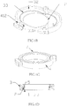
- the present invention utilizes a cushion ring 2 that is provided on fixture device 3. As shown in Fig 1B , a cushion ring 2 is connected to the inner side of the blade 32 (which is closest to the balanus ferrule 1 during a circumcision procedure).
- the groove 33 is formed on the inside circumference of the blade 32.
- the cross-section of groove 33 is of semi-circular shape.
- the cross-section of the cushion ring interconnected with groove 33 is of circular shape, and the diameter thereof is less than or equal to that of the circular groove.
- the circumference of the cushion ring is about equal to that of the blade edge when the fixture device is closed.
- the cushion ring is typically held in place by the geometry of the groove and ring.
- the groove 33 may, alternatively, comprise an arc, semi-elliptic, square, or triangular shape, any of which can be made to accept the cushion ring 2.
- the inner side of the blade (H1) can be equal to or thicker than that of outer side of the blade (H2).
- the blade of the left semi-ferrule 3A comprises a first blade mating portion 311A and the blade of the right semi-ferrule 3B comprises a second blade mating portion 311B at the open end of the blade, respectively.
- These portions of the blade are designed to slide over each other, or overlap, to form a complete blade structure (e.g., ring) as the fixture device is placed into a closed position.
- the thickness of both the first and second blade mating portions are thinner than the majority of the blade structures.
- the mating portions comprise rounded edges.
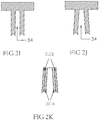
- Figs 2F, 2G, and 2H illustrate three embodiments of the first and second mating blade portions when the fixture device is in a closed position.
- the groove formed on the interior circumference of the blade extends into the mating portions, however the cross section of the groove in the mating portions are half of what they are in the majority of the blade.
- the groove that is formed on the majority of the blade continues uninterrupted in the mating portions, as the groove is completed as the mating portions align with one another.
- the fixture device 3 comprises a two-section design, each section having an open end and a connecting end.
- fixture device 3 comprises the left semi-ferrule 3A and right semi-ferrule 3B.
- the connecting ends are rotatably connected to one another via a hinged connection 35, which comprises connecting linear groove 351 on one semi-ferrule and connecting rod shaft 352 on the other semi-ferrule.
- the open end on left semi-ferrule 3A comprises a means for mating with a reciprocal means located on the open end of the right semi-ferrule 3B. In this way, the fixture device can be easily applied and removed during circumcision surgery.
- first and second mating blade portions effectively prevent the blade from pinching the penis when using the circumcision device during surgery.
- the structure effectively guides the cushion ring into the blade groove.
- the cushion ring fits easily within the complete groove formed as the fixture device is closed, and is not clamped or pinched at the open or connecting ends.
- each semi-ferrule may comprise two or more blade.
- each semi-ferrule comprises two blade, each comprising an inner circumference having a groove to accommodate a cushion ring, while a cavity 34 is formed between the two blade for containing cotton wool or ointment.
- the left semi-ferrule comprises two mating blade portions 311A (inner)
- the right semi-ferrule comprises two mating blade portions 311B (outer). As the circumcision device is closed, the two mating blade portions 311B overlap the two mating blade portions 311A to form a complete ring structure.
- the cushion ring 2 may comprise the linear structure shown in Fig 3D , which can be directly inserted into groove 33 of the blade.
- each end 211 and 212 of the linear structure are cut off at an angle, such as 45 degrees, and these ends lie on top of the first blade mating portion and second blade mating portion, respectively, after it has been inserted into the groove.
- the linear cushion ring forms a full ring shape.
- the cushion ring 2' comprises a groove 21 that overlaps the inner circumference of one or both blade. As shown in Figs 4F, 4G and 4H , groove 21 may alternatively overlap a portion of or an entire blade.
- the thickness of the inner circumference of a blade (H1) is thinner than the outer circumference (H2) thickness.
- the width (H1) can be equal to or larger than H2. This design can reduce the amount of materials needed to manufacture the blade/cushion ring.
- Another advantage is that it may be desirable for the cushion ring 2 to be attached to the blade.
- Fig 4C illustrates that width H1 is equal to width H2, while Figs 4D and 4E illustrate that width H1 is greater than width H2.
- the method in which H1 is greater than or equal to H2 is desirable so that the cushion ring 2 may be steadily affixed to the blade.
- the cushion ring 2' is manufactured from medical non-toxic silica-gel and may be directly adhered to the blade inner circumference.
- the cushion ring 2 may be manufactured from virtually any combination of plastics and silica-gel.
- the blade are manufactured from a relatively hard material, such as plastic, while the cushion ring is manufactured with a less-hard substance, such as silica-gel, so that the cushion ring fits adheres to the groove by virtue of an integral formation between the plastic and the silica-gel.
- the surrounding wall 31 may be coated with a silica-gel layer 22 that adheres to the surrounding wall 31 (i.e., fixture device) through a single integral formation between plastics and silica-gel.
- the entire fixture device is coated with a silica-gel layer, enabling the penis to directly contact this soft surface, thereby effectively increasing the patient's comfort.
- Figs 5A, 5B, and 5C illustrate three views of balanus ferrule 1 shown in Fig. 1A .
- a first rim 11 and a second rim 12 create a circular cavity 13 between the first rim 11 and the second rim 12.
- a circular elastic pad 5 comprises a ring made of an elastic material, such as rubber or other stretchable synthetic material.
- the elastic pad 5 when in use, is stretched over one of the rims (either rim 11 or rim 12) of the balanus ferrule 1, where it then fits snugly around the circular cavity.
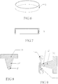
- Fig 8 illustrates a cross section of one of the blade and cushion ring inserted into a groove formed along an interior circumference of the blade.
- Fig 9 illustrates a cross section of the blade/ring combination of Fig 8 in contact with a cross section of the elastic pad 5 placed around the balanus ferrule 1.
- a penis is placed through the balanus ferrule 1 having the circular elastic pad 5 in place over its circular cavity.
- the prepuce 7 is unfurled to cover the balanus ferrule 1 with the unfurled portion of the prepuce extending from the ferrule.
- the circular cushion ring 2 is placed around the exterior surface of the prepuce.
- the fixture device 3 in an open position, is placed around the cushion ring 2, aligning the groove in each blade with the cushion ring 2.
- the fixing device is closed by bringing the two open ends of each semi-ferrule together and locking the fixing device in a closed position using the buckling device.
- the result shown in a cross-sectional view, is shown in Fig 10 .
- the first and second mating blade portions can effectively prevent the skin on the penis from being pinched at the open and connecting ends of the fixture device and, additionally, the circular cushion ring is easily guided into the blade groove.
- Both the circular cushion ring and surrounding elastic pad are typically made of soft, non-toxic medical silica-gel, providing a certain degree of expansion and effectively minimizing the pain and discomfort normally associated with circumcision surgery.
- the outer circumference of the surrounding wall of the fixture device comprises a beautiful arc shape.
- the exterior circumference of the balanus ferrule comprises a curved profile which can prevent the blade sliding from the middle to either rim of the balanus ferrule.
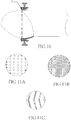
- a micro mechanism that prevents skin adhesion may be provided on the surface of either the circular cushion ring 2, circular elastic pad 5, or both.
- the micro mechanism may comprise depressions or raised portions, such as the sinking and/or bulging dots shown in Fig 11A , the crossed bulging and/or sinking streaks shown in Fig 11B , or the grooves and/or protrusions shown in Fig 11C . Due to the existence of the micro mechanisms, removal of the circumcision apparatus reduces the occurrence of skin adhesion, making the process of removing the circumcision apparatus easier.
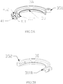
- the fixture device 3 and balanus ferrule 1 comprise an elliptic structure. This structure may more closely resemble the cross section of an actual penis, especially the shape of the coronal sulcus. As shown in Figs 12C and 13 , the fixture device and the balanus ferrule are elliptical and oblique. As shown in Fig 14 , the circumcision apparatus closely matches the oblique shape of coronal sulcus, providing more comfort to the patient and ease of operation for the surgeon.
- a notch 14 is formed for accommodating the frenulum of prepuce is provided at one side of the first and second edges of the balanus ferrule 1. While in use, the balanus ferrule may be rotated so that notch 14 accommodates the frenulum of prepuce.
- the notch 14 advantageously protects the frenulum and allows the circumcision device to more closely fit a human penis. Thus, the pain resulting from chaffing of the frenulum during a nocturnal erection may be reduced, thus increasing patient comfort.
- the fixture device is closed (only closed not opened to avoid reuse of the apparatus) by the use of a buckling device.
- the buckling device may comprise any number of structures known in the art, such as a screw located on an open end of one of the semi-ferrules and a threaded linear groove at the other open end on the other semi-ferrule that comprise fixture device 3.
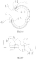
- the buckling device 4 comprises the detent block structure shown in Figs 16, 17 . As shown in Fig 17 , the buckling device comprises an upper scalariform detent block 41 and a lower scalariform detent block 42 that are arranged in a "staggered" formation.
- the first mating blade portion 311A lies in a plane slightly above the lower scalariform detent block 41 and the second mating blade portion 311B lies in a plane slightly under the upper scalariform detent block 42, creating a fixture device that is self-contained and capable of being opened and closed using the buckling device.
- the aforesaid upper scalariform detent block 41 and lower scalariform detent block 42 may comprise a hook and linear groove that corresponds with each other.
- an upper hook 13 may be provide at the outer end of upper scalariform detent block 41 and a lower linear groove 16 is provided at the inner end of the upper scalariform detent block 41
- a lower hook 14 is provide at the outer end of lower scalariform detent block 42
- an upper linear groove 15 is provided at the inner end of the lower scalariform detent block 42.
- the upper hook 13 interacts with the upper linear groove 15, while the lower hook 14 interacts with the lower linear groove 16.
- the hook and linear groove further assures that the fixture device will remain closed.
- the inner sides of the upper scalariform detent block 41 and lower scalariform detent block 42 may comprise incline surfaces, and incline projecting portions, located on the surrounding walls, the incline projecting portions substantially matching the incline surfaces.
- This feature is shown, illustrating a first incline surface 411 and a first incline projecting portion 412 on the upper scalariform detent block 41 and a second incline surface 421 and second incline projecting portion 422 on the lower scalariform detent block 42.
- the upper hook 13 is provided at the outer side of the first incline surface 411 and the lower hook 14 is provided at the outer side of second incline surface 421.
- the lower linear groove 16 is provided at the end of the first incline projecting portion 412 and the upper linear groove 15 at the end of the second incline projecting portion 422.
- the hooks and linear grooves or holes further substantially match with the upper and lower tooth-like detent blocks, ensuring effective vertical and horizontal locking with each other, and preventing accidental openings of the fixture device 3.
- an unlocking hole 43 may be provided on the lower scalariform detent block 42 or on the upper scalariform detent block 41.
- a special tool may be inserted into the unlocking linear groove 43, thereby prying the detent blocks from one another and allowing removal of the circumcision apparatus.
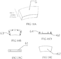
- Fig 19A and 19E illustrate a protective cover 6 that may be placed onto the buckling device to prevent accidental opening of the fixture device after surgery.
- the protective cover 6 comprises a cover body having a bottom plate, two side walls and a top wall.
- Cap 62 substantially matches the bottom plate so that protective cover 6 forms a cavity 61 that substantially matches the contour of the buckling device when cap 62 is placed on top of the cover body.
- the cap 62 is secured to the cover body typically using one or more fastening devices, such as screws, bolts, Velcro, etc., or using one or more rods 64 attached to cap 62, that may be snugly inserted into corresponding linear grooves 63 formed on the cover body rim.
- the protective cover may be constructed of, in one embodiment, resilient silica-gel for convenient use.
- the protective cover can effectively minimize the risk of accidental openings of the fixture device after surgery, which may result from an erection of the penis, thereby increasing the likelihood of a successful operation.
- Fixture device 30 comprises a C-shaped ring that is made of soft materials that may enable it to open wider when needed.
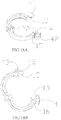
- Figs 21A and 21B illustrate an embodiment where the fixture device comprises three sections.
- the three-section design effectively eliminates the single hinge from the center of the circumcision apparatus and replaces it with the two hinges shown in Figs 21A and 21B .
- the placement of the two hinges allow the scrotum to be placed therebetween, thereby reducing friction with the scrotum.
Landscapes
- Health & Medical Sciences (AREA)
- Life Sciences & Earth Sciences (AREA)
- Surgery (AREA)
- Heart & Thoracic Surgery (AREA)
- Engineering & Computer Science (AREA)
- Biomedical Technology (AREA)
- Nuclear Medicine, Radiotherapy & Molecular Imaging (AREA)
- Medical Informatics (AREA)
- Molecular Biology (AREA)
- Animal Behavior & Ethology (AREA)
- General Health & Medical Sciences (AREA)
- Public Health (AREA)
- Veterinary Medicine (AREA)
- Orthopedics, Nursing, And Contraception (AREA)
- Surgical Instruments (AREA)
Claims (22)
- Appareil de circoncision jetable, comportant :un dispositif de fixation (3) comportant une paroi périphérique (31), la paroi périphérique comportant une ouverture ;une lame (32) formée le long d'une surface intérieure de la paroi périphérique, la lame comportant une première partie d'accouplement de lame (311A) et une deuxième partie d'accouplement de lame (311B) qui s'accouplent l'une par rapport à l'autre quand le dispositif de fixation est dans une position fermée, la lame comportant par ailleurs un bord circonférentiel intérieur de lame ;un moyen (41, 42) de maintien du dispositif de fixation dans une position fermée ; etune bague de gland (1) ;caractérisé par un anneau à coussinet (2, 2') à des fins de positionnement contre la lame, la bague de gland étant agencée à des fins de mise en place à l'intérieur de l'anneau à coussinet et du dispositif de fixation, de telle sorte que, lors de l'utilisation, un prépuce (7) peut être intercalé entre l'anneau à coussinet et la bague de gland et l'anneau à coussinet peut être intercalé entre la lame et le prépuce ; etune rainure (21, 33), la rainure (33) étant formée le long du bord circonférentiel intérieur de la lame (32) à des fins de réception de l'anneau à coussinet (2), ou étant formée (21) le long d'une circonférence de l'anneau à coussinet (2') à des fins de réception du bord circonférentiel intérieur de la lame (32) ou à des fins de réception de la totalité de la lame (32).
- Appareil selon la revendication 1, dans lequel :la rainure (33) est formée le long du bord circonférentiel intérieur de la lame à des fins de réception de l'anneau à coussinet (2).
- Appareil selon la revendication 1, dans lequel :la rainure (21) est formée le long d'une circonférence de l'anneau à coussinet (2') à des fins de réception du bord circonférentiel intérieur de la lame.
- Appareil selon la revendication 1, dans lequel :la rainure (21) est formée le long d'une circonférence de l'anneau à coussinet (2') et la totalité de la lame est placée à l'intérieur de la rainure.
- Appareil selon les revendications 1 ou 3 ou 4, dans lequel :l'anneau à coussinet (2, 2') est réalisé en gel de silice et la lame (32) est réalisée en plastique, et l'anneau à coussinet adhère à la lame par une formation solidaire entre le plastique et le gel de silice.
- Appareil selon la revendication 5, dans lequel :le dispositif de fixation (3) est revêtu au moyen d'une couche de gel de silice (22), et la couche de gel de silice adhère au dispositif de fixation par une formation solidaire entre le plastique et le gel de silice.
- Appareil selon les revendications 1 ou 2 ou 3 ou 4, dans lequel :l'épaisseur (H1) du bord circonférentiel intérieur de la lame est supérieure ou égale à l'épaisseur (H2) du bord circonférentiel extérieur de la lame là où la lame entre en contact avec une surface circonférentielle intérieure du dispositif de fixation.
- Appareil selon les revendications 1 ou 2 ou 3 ou 4, comportant par ailleurs :un tampon élastique circulaire (5), dans lequel le tampon élastique est placé autour de la partie extérieure de la bague de gland (1).
- Appareil selon la revendication 8, dans lequel la bague de gland (1) comporte par ailleurs :un premier rebord (11) situé sur un premier côté de la bague de gland ; etun deuxième rebord (12) situé sur un deuxième côté de la bague de gland ; dans lequel les premier et deuxième rebords forment une cavité de forme annulaire (13) sur laquelle le tampon élastique (5) repose.
- Appareil selon la revendication 9, dans lequel l'anneau à coussinet et le tampon élastique comportent un micro-mécanisme servant à empêcher toute adhésion de la peau sur l'anneau à coussinet et le tampon élastique.
- Appareil selon la revendication 10, dans lequel :le micro-mécanisme est sélectionné dans le groupe constitué par des points s'affaissant et bombés, des lignes s'affaissant et bombées croisées, des rainures, des parties saillantes, et une structure irrégulière.
- Appareil selon la revendication 1, dans lequel :le dispositif de fixation (3) et la bague de gland (1) comportent une structure de forme elliptique ou de forme obliquement elliptique correspondant à une section en coupe d'un sillon coronal.
- Appareil selon la revendication 1, dans lequel la bague de gland (1) comporte par ailleurs une entaille (14) à des fins de réception d'un frein de prépuce.
- Appareil selon la revendication 1 ou la revendication 12, dans lequel :le dispositif de fixation (3) est en forme de C.
- Appareil selon la revendication 1 ou la revendication 12, dans lequel :le dispositif de fixation comporte trois sections connectées ensemble au niveau de deux points d'articulation, les points d'articulation étant décalés l'un par rapport à l'autre de telle sorte qu'ils minimalisent le contact avec un scrotum au cours d'une intervention chirurgicale de circoncision.
- Appareil selon la revendication 1, dans lequel le moyen de maintien du dispositif de fixation dans une position fermée comporte des blocs de détente en disposition scalariforme supérieur et inférieur (41, 42), chacun des blocs de détente en disposition scalariforme comportant un crochet (13, 14) et un trou, dans lequel les crochets sont dimensionnés et formés à des fins d'adaptation dans les trous, respectivement.
- Appareil selon la revendication 1, dans lequel :le moyen de maintien du dispositif de fixation dans une position fermée comporte une vis sur une extrémité du dispositif de fixation et un trou taraudé linéaire sur l'autre extrémité du dispositif de fixation.
- Appareil selon la revendication 1 ou la revendication 16, comportant par ailleurs un capuchon de protection (6) dimensionné et formé à des fins d'adaptation sur le moyen de maintien du dispositif de fixation dans une position fermée.
- Appareil selon la revendication 2, dans lequel :la section en coupe de la rainure (33) est sélectionnée dans le groupe constitué par un arc, un demi-cercle, une semi-ellipse, et un triangle ; etla section en coupe de la première partie d'accouplement de lame (311A) et de la deuxième partie d'accouplement de lame (311B) combinées est sélectionnée dans le groupe constitué par un arc, un demi-cercle, une semi-ellipse, et un triangle ; etl'anneau à coussinet (2) comportant une section en coupe correspondant sensiblement à la section en coupe de la rainure (33).
- Appareil selon la revendication 2, dans lequel :l'anneau à coussinet (2) est de forme annulaire et la circonférence de celui-ci correspond à celle de la lame (32).
- Appareil selon les revendications 1, 3 ou 4, dans lequel :le dispositif de fixation (3) comporte une, deux ou trois lames (32).
- Appareil selon les revendications 1, 3 ou 4, dans lequel :des angles arrondis sont mis en oeuvre au niveau des première et deuxième parties d'accouplement de lame (311A, 311B).
Priority Applications (4)
| Application Number | Priority Date | Filing Date | Title |
|---|---|---|---|
| SI201231069T SI2856954T1 (sl) | 2012-05-28 | 2012-10-26 | Obrezovalni anastomat za enkratno uporabo |
| HRP20171401TT HRP20171401T1 (hr) | 2012-05-28 | 2012-10-26 | Jednokratni uređaj za anastomozu za obrezivanje |
| RS20170909A RS56341B1 (sr) | 2012-05-28 | 2012-10-26 | Anastomski uređaj za obrezivanje za jednokratnu upotrebu |
| PL12877095T PL2856954T3 (pl) | 2012-05-28 | 2012-10-26 | Jednorazowy anastomat do obrzezania |
Applications Claiming Priority (2)
| Application Number | Priority Date | Filing Date | Title |
|---|---|---|---|
| CN201210169127.7A CN102743211B (zh) | 2012-05-28 | 2012-05-28 | 一次性包皮环切吻合器 |
| PCT/CN2012/001438 WO2013173954A1 (fr) | 2012-05-25 | 2012-10-26 | Dispositif d'anastomose jetable pour la circoncision |
Publications (3)
| Publication Number | Publication Date |
|---|---|
| EP2856954A1 EP2856954A1 (fr) | 2015-04-08 |
| EP2856954A4 EP2856954A4 (fr) | 2015-11-25 |
| EP2856954B1 true EP2856954B1 (fr) | 2017-06-21 |
Family
ID=47023962
Family Applications (1)
| Application Number | Title | Priority Date | Filing Date |
|---|---|---|---|
| EP12877095.5A Active EP2856954B1 (fr) | 2012-05-28 | 2012-10-26 | Dispositif d'anastomose jetable pour la circoncision |
Country Status (17)
| Country | Link |
|---|---|
| EP (1) | EP2856954B1 (fr) |
| CN (1) | CN102743211B (fr) |
| AP (1) | AP2014008123A0 (fr) |
| CA (1) | CA2876510C (fr) |
| CY (1) | CY1119700T1 (fr) |
| DK (1) | DK2856954T3 (fr) |
| EA (2) | EA032400B9 (fr) |
| ES (1) | ES2639942T3 (fr) |
| HR (1) | HRP20171401T1 (fr) |
| HU (1) | HUE034454T2 (fr) |
| LT (1) | LT2856954T (fr) |
| PL (1) | PL2856954T3 (fr) |
| PT (1) | PT2856954T (fr) |
| RS (1) | RS56341B1 (fr) |
| SI (1) | SI2856954T1 (fr) |
| WO (1) | WO2013173954A1 (fr) |
| ZA (1) | ZA201409503B (fr) |
Families Citing this family (22)
| Publication number | Priority date | Publication date | Assignee | Title |
|---|---|---|---|---|
| CN102743211B (zh) * | 2012-05-28 | 2015-08-19 | 商建忠 | 一次性包皮环切吻合器 |
| WO2014071871A1 (fr) | 2012-11-08 | 2014-05-15 | 张首府 | Dispositif d'anastomose pour circoncision |
| CN103054630B (zh) * | 2013-01-27 | 2014-08-13 | 张首府 | 包皮环切吻合器 |
| CN103536343B (zh) * | 2013-11-14 | 2016-03-09 | 倪伟平 | 一种包皮环切器 |
| CN103767771A (zh) * | 2014-01-11 | 2014-05-07 | 商建忠 | 一次性包皮环切吻合器 |
| CN103767770A (zh) * | 2014-01-11 | 2014-05-07 | 商建忠 | 一次性包皮环切吻合器 |
| CN103767773A (zh) * | 2014-01-23 | 2014-05-07 | 商建忠 | 一次性包皮环切吻合器 |
| CN107411789B (zh) * | 2016-05-24 | 2023-08-15 | 温州冠美医疗科技有限公司 | 一种包皮切割器的单边垫片组合式缝合钉 |
| CN106333731B (zh) * | 2016-10-28 | 2020-04-10 | 广州德脉医疗器械有限公司 | 一种带包皮内板切口保护套的凹形座装置 |
| CN107088078A (zh) * | 2016-12-05 | 2017-08-25 | 温州冠美医疗科技有限公司 | 一种包皮切割缝合器 |
| CN106580404A (zh) * | 2017-01-22 | 2017-04-26 | 芜湖商环科技有限公司 | 一次性包皮环切吻合器 |
| CN106580403A (zh) * | 2017-01-22 | 2017-04-26 | 芜湖商环科技有限公司 | 一次性包皮环切吻合器 |
| CN108433788B (zh) * | 2018-03-21 | 2023-10-31 | 江西狼和医疗器械有限公司 | 一种环切吻合器 |
| CN109674501B (zh) * | 2019-03-06 | 2025-03-11 | 江苏特普优微创医疗科技有限公司 | 一种一次性微创腔镜切割吻合器用连接器 |
| CN112006754B (zh) * | 2020-09-15 | 2022-03-25 | 微尔创(武汉)医疗科技有限公司 | 一种自动式包皮弹力线套扎吻合组件 |
| CN112006752B (zh) * | 2020-09-15 | 2022-06-21 | 微尔创(武汉)医疗科技有限公司 | 一种弹力线套扎包皮罩组件 |
| CN112006753B (zh) * | 2020-09-15 | 2022-06-21 | 微尔创(武汉)医疗科技有限公司 | 一种手动式包皮弹力线套扎吻合组件 |
| CN112006751B (zh) * | 2020-09-15 | 2022-04-05 | 微尔创(武汉)医疗科技有限公司 | 一种弹力线包皮环收紧结构 |
| CN114711989B (zh) * | 2021-01-06 | 2024-12-24 | 上海康路联医疗科技有限公司 | 包皮定位组件 |
| CN113925574B (zh) * | 2021-11-18 | 2024-05-24 | 长沙汇顶医疗科技有限责任公司 | 一种含有套扎器和套扎枪的包皮套扎组件 |
| CN114027944B (zh) * | 2021-12-17 | 2024-03-26 | 长沙汇顶医疗科技有限责任公司 | 一种收紧均匀的包皮套扎器结构 |
| CN116327354B (zh) * | 2023-03-03 | 2024-04-05 | 赫美康健(北京)医疗器械有限公司 | 一种基于激光技术的包皮环切器固定装置及操作方法 |
Family Cites Families (15)
| Publication number | Priority date | Publication date | Assignee | Title |
|---|---|---|---|---|
| US5797921A (en) * | 1997-03-17 | 1998-08-25 | International Technidyne Corporation | Disposable circumcision apparatus and method of use |
| CN2694913Y (zh) * | 2003-10-27 | 2005-04-27 | 商建忠 | 包皮环切器 |
| CN101313867B (zh) * | 2008-06-25 | 2010-09-01 | 商建忠 | 包皮环切吻合器 |
| CN101991456B (zh) * | 2009-08-24 | 2013-07-17 | 谭国梁 | 可与阴茎互动胀缩的包皮环扎切器 |
| CN201710421U (zh) * | 2010-06-02 | 2011-01-19 | 商建忠 | 包皮环切器 |
| CN102327140A (zh) * | 2010-07-12 | 2012-01-25 | 商建忠 | 一次性包皮环切吻合器 |
| CN102451031B (zh) * | 2010-10-25 | 2013-06-05 | 商建忠 | 一次性包皮环切吻合器 |
| CN102743212B (zh) * | 2010-12-08 | 2015-12-02 | 商建忠 | 用于套设包皮环切吻合器环形弹性圈的辅助装置 |
| CN102068297B (zh) * | 2010-12-23 | 2012-07-04 | 商建忠 | 一次性包皮环切吻合器 |
| CN102028520A (zh) * | 2010-12-27 | 2011-04-27 | 商建忠 | 一次性包皮环切吻合器 |
| CN102309358A (zh) * | 2011-10-05 | 2012-01-11 | 商建忠 | 一次性包皮环切吻合器 |
| CN202537613U (zh) * | 2011-11-14 | 2012-11-21 | 商建忠 | 一次性包皮环切吻合器 |
| CN102488544A (zh) * | 2011-11-14 | 2012-06-13 | 商建忠 | 一次性包皮环切吻合器 |
| CN102743211B (zh) * | 2012-05-28 | 2015-08-19 | 商建忠 | 一次性包皮环切吻合器 |
| CN202604965U (zh) * | 2012-05-28 | 2012-12-19 | 商建忠 | 一次性包皮环切吻合器 |
-
2012
- 2012-05-28 CN CN201210169127.7A patent/CN102743211B/zh active Active
- 2012-10-26 RS RS20170909A patent/RS56341B1/sr unknown
- 2012-10-26 ES ES12877095.5T patent/ES2639942T3/es active Active
- 2012-10-26 PT PT128770955T patent/PT2856954T/pt unknown
- 2012-10-26 HU HUE12877095A patent/HUE034454T2/en unknown
- 2012-10-26 EA EA201790347A patent/EA032400B9/ru active IP Right Revival
- 2012-10-26 CA CA2876510A patent/CA2876510C/fr active Active
- 2012-10-26 EP EP12877095.5A patent/EP2856954B1/fr active Active
- 2012-10-26 EA EA201492143A patent/EA028137B1/ru active IP Right Revival
- 2012-10-26 AP AP2014008123A patent/AP2014008123A0/xx unknown
- 2012-10-26 SI SI201231069T patent/SI2856954T1/sl unknown
- 2012-10-26 HR HRP20171401TT patent/HRP20171401T1/hr unknown
- 2012-10-26 PL PL12877095T patent/PL2856954T3/pl unknown
- 2012-10-26 DK DK12877095.5T patent/DK2856954T3/en active
- 2012-10-26 LT LTEP12877095.5T patent/LT2856954T/lt unknown
- 2012-10-26 WO PCT/CN2012/001438 patent/WO2013173954A1/fr not_active Ceased
-
2014
- 2014-12-23 ZA ZA2014/09503A patent/ZA201409503B/en unknown
-
2017
- 2017-09-20 CY CY20171100994T patent/CY1119700T1/el unknown
Also Published As
| Publication number | Publication date |
|---|---|
| CA2876510C (fr) | 2020-01-07 |
| EA201790347A1 (ru) | 2017-06-30 |
| WO2013173954A1 (fr) | 2013-11-28 |
| AP2014008123A0 (en) | 2014-12-31 |
| LT2856954T (lt) | 2017-11-27 |
| EP2856954A4 (fr) | 2015-11-25 |
| DK2856954T3 (en) | 2017-10-09 |
| CN102743211B (zh) | 2015-08-19 |
| EA201492143A1 (ru) | 2015-04-30 |
| ZA201409503B (en) | 2016-09-28 |
| PT2856954T (pt) | 2017-09-08 |
| ES2639942T3 (es) | 2017-10-30 |
| EP2856954A1 (fr) | 2015-04-08 |
| EA032400B1 (ru) | 2019-05-31 |
| RS56341B1 (sr) | 2017-12-29 |
| HUE034454T2 (en) | 2018-02-28 |
| WO2013173954A8 (fr) | 2014-12-31 |
| CY1119700T1 (el) | 2018-04-04 |
| PL2856954T3 (pl) | 2018-01-31 |
| CA2876510A1 (fr) | 2013-11-28 |
| SI2856954T1 (sl) | 2017-11-30 |
| HRP20171401T1 (hr) | 2017-11-03 |
| EA028137B1 (ru) | 2017-10-31 |
| CN102743211A (zh) | 2012-10-24 |
| EA032400B9 (ru) | 2019-07-31 |
Similar Documents
| Publication | Publication Date | Title |
|---|---|---|
| EP2856954B1 (fr) | Dispositif d'anastomose jetable pour la circoncision | |
| US10456162B2 (en) | Disposable apparatus for fitly circumcising a penis | |
| RU2604948C2 (ru) | Усовершенствованный хирургический инструмент, такой как расширитель | |
| CN202604965U (zh) | 一次性包皮环切吻合器 | |
| US20030177648A1 (en) | Extension shaver and method | |
| EP3466370B1 (fr) | Pince pour prévenir l'incontinence urinaire masculine | |
| US6740095B2 (en) | Umbilical cord clamp and cutter | |
| MXPA06012180A (es) | Dispositivo de fijacion de miembro tubular. | |
| OA16690A (en) | Disposable apparatus for fitly circumcising a penis. | |
| CN215230790U (zh) | 一种腰大池引流固定装置 | |
| KR101895871B1 (ko) | 인공항문 보호판 재단장치 | |
| CN210354841U (zh) | 一种人体解剖肌层膜层分开器 | |
| CN215275296U (zh) | 一种胸腔闭式引流置管钳 | |
| CN221787686U (zh) | 一种输液固定手板 | |
| CN223196056U (zh) | 一次性改良内镜口垫 | |
| CN219896339U (zh) | 一种多功能睑板腺按摩夹 | |
| CN223183690U (zh) | 一种耳部辅助治疗装置 | |
| CN210991123U (zh) | 一种嵌入式手术钳 | |
| CN113456133B (zh) | 一种开睑器 | |
| CN213191811U (zh) | 一种胰岛素辅助注射装置 | |
| CN209220684U (zh) | 防耳廓假性囊肿复发的夹耳器 | |
| CN209474944U (zh) | 滴眼药水辅助器 | |
| HK1195865B (en) | Surgical instrument | |
| CN117838443A (zh) | 外生殖器术后保护器 | |
| JP3049708U (ja) | 陰茎絞扼リングの装着具 |
Legal Events
| Date | Code | Title | Description |
|---|---|---|---|
| PUAI | Public reference made under article 153(3) epc to a published international application that has entered the european phase |
Free format text: ORIGINAL CODE: 0009012 |
|
| 17P | Request for examination filed |
Effective date: 20141218 |
|
| AK | Designated contracting states |
Kind code of ref document: A1 Designated state(s): AL AT BE BG CH CY CZ DE DK EE ES FI FR GB GR HR HU IE IS IT LI LT LU LV MC MK MT NL NO PL PT RO RS SE SI SK SM TR |
|
| AX | Request for extension of the european patent |
Extension state: BA ME |
|
| RA4 | Supplementary search report drawn up and despatched (corrected) |
Effective date: 20151027 |
|
| RIC1 | Information provided on ipc code assigned before grant |
Ipc: A61B 17/326 20060101AFI20151021BHEP Ipc: A61B 17/115 20060101ALI20151021BHEP |
|
| 17Q | First examination report despatched |
Effective date: 20160706 |
|
| GRAP | Despatch of communication of intention to grant a patent |
Free format text: ORIGINAL CODE: EPIDOSNIGR1 |
|
| INTG | Intention to grant announced |
Effective date: 20170118 |
|
| GRAS | Grant fee paid |
Free format text: ORIGINAL CODE: EPIDOSNIGR3 |
|
| GRAA | (expected) grant |
Free format text: ORIGINAL CODE: 0009210 |
|
| AK | Designated contracting states |
Kind code of ref document: B1 Designated state(s): AL AT BE BG CH CY CZ DE DK EE ES FI FR GB GR HR HU IE IS IT LI LT LU LV MC MK MT NL NO PL PT RO RS SE SI SK SM TR |
|
| AX | Request for extension of the european patent |
Extension state: BA ME |
|
| REG | Reference to a national code |
Ref country code: GB Ref legal event code: FG4D |
|
| REG | Reference to a national code |
Ref country code: CH Ref legal event code: EP |
|
| REG | Reference to a national code |
Ref country code: IE Ref legal event code: FG4D |
|
| REG | Reference to a national code |
Ref country code: AT Ref legal event code: REF Ref document number: 902231 Country of ref document: AT Kind code of ref document: T Effective date: 20170715 |
|
| REG | Reference to a national code |
Ref country code: DE Ref legal event code: R096 Ref document number: 602012033852 Country of ref document: DE |
|
| REG | Reference to a national code |
Ref country code: PT Ref legal event code: SC4A Ref document number: 2856954 Country of ref document: PT Date of ref document: 20170908 Kind code of ref document: T Free format text: AVAILABILITY OF NATIONAL TRANSLATION Effective date: 20170904 |
|
| REG | Reference to a national code |
Ref country code: RO Ref legal event code: EPE |
|
| REG | Reference to a national code |
Ref country code: HR Ref legal event code: TUEP Ref document number: P20171401 Country of ref document: HR |
|
| REG | Reference to a national code |
Ref country code: NL Ref legal event code: FP |
|
| REG | Reference to a national code |
Ref country code: DK Ref legal event code: T3 Effective date: 20171003 |
|
| REG | Reference to a national code |
Ref country code: SE Ref legal event code: TRGR |
|
| REG | Reference to a national code |
Ref country code: ES Ref legal event code: FG2A Ref document number: 2639942 Country of ref document: ES Kind code of ref document: T3 Effective date: 20171030 |
|
| REG | Reference to a national code |
Ref country code: FR Ref legal event code: PLFP Year of fee payment: 6 |
|
| REG | Reference to a national code |
Ref country code: HR Ref legal event code: T1PR Ref document number: P20171401 Country of ref document: HR |
|
| REG | Reference to a national code |
Ref country code: NO Ref legal event code: T2 Effective date: 20170621 |
|
| REG | Reference to a national code |
Ref country code: EE Ref legal event code: FG4A Ref document number: E014231 Country of ref document: EE Effective date: 20170920 |
|
| REG | Reference to a national code |
Ref country code: SK Ref legal event code: T3 Ref document number: E 25264 Country of ref document: SK |
|
| PG25 | Lapsed in a contracting state [announced via postgrant information from national office to epo] |
Ref country code: IS Free format text: LAPSE BECAUSE OF FAILURE TO SUBMIT A TRANSLATION OF THE DESCRIPTION OR TO PAY THE FEE WITHIN THE PRESCRIBED TIME-LIMIT Effective date: 20171021 Ref country code: SM Free format text: LAPSE BECAUSE OF FAILURE TO SUBMIT A TRANSLATION OF THE DESCRIPTION OR TO PAY THE FEE WITHIN THE PRESCRIBED TIME-LIMIT Effective date: 20170621 |
|
| REG | Reference to a national code |
Ref country code: HU Ref legal event code: AG4A Ref document number: E034454 Country of ref document: HU |
|
| REG | Reference to a national code |
Ref country code: GR Ref legal event code: EP Ref document number: 20170402475 Country of ref document: GR Effective date: 20180309 |
|
| REG | Reference to a national code |
Ref country code: DE Ref legal event code: R097 Ref document number: 602012033852 Country of ref document: DE |
|
| REG | Reference to a national code |
Ref country code: HU Ref legal event code: HC9C |
|
| PLBE | No opposition filed within time limit |
Free format text: ORIGINAL CODE: 0009261 |
|
| STAA | Information on the status of an ep patent application or granted ep patent |
Free format text: STATUS: NO OPPOSITION FILED WITHIN TIME LIMIT |
|
| 26N | No opposition filed |
Effective date: 20180322 |
|
| REG | Reference to a national code |
Ref country code: FR Ref legal event code: PLFP Year of fee payment: 7 |
|
| REG | Reference to a national code |
Ref country code: HR Ref legal event code: ODRP Ref document number: P20171401 Country of ref document: HR Payment date: 20191011 Year of fee payment: 8 |
|
| REG | Reference to a national code |
Ref country code: HR Ref legal event code: ODRP Ref document number: P20171401 Country of ref document: HR Payment date: 20201020 Year of fee payment: 9 |
|
| REG | Reference to a national code |
Ref country code: AT Ref legal event code: UEP Ref document number: 902231 Country of ref document: AT Kind code of ref document: T Effective date: 20170621 |
|
| REG | Reference to a national code |
Ref country code: HR Ref legal event code: ODRP Ref document number: P20171401 Country of ref document: HR Payment date: 20211020 Year of fee payment: 10 |
|
| REG | Reference to a national code |
Ref country code: HR Ref legal event code: ODRP Ref document number: P20171401 Country of ref document: HR Payment date: 20221019 Year of fee payment: 11 |
|
| REG | Reference to a national code |
Ref country code: HR Ref legal event code: ODRP Ref document number: P20171401 Country of ref document: HR Payment date: 20231025 Year of fee payment: 12 |
|
| REG | Reference to a national code |
Ref country code: HR Ref legal event code: ODRP Ref document number: P20171401 Country of ref document: HR Payment date: 20241017 Year of fee payment: 13 |
|
| PGFP | Annual fee paid to national office [announced via postgrant information from national office to epo] |
Ref country code: MT Payment date: 20250923 Year of fee payment: 14 |
|
| REG | Reference to a national code |
Ref country code: CH Ref legal event code: U11 Free format text: ST27 STATUS EVENT CODE: U-0-0-U10-U11 (AS PROVIDED BY THE NATIONAL OFFICE) Effective date: 20251101 |
|
| REG | Reference to a national code |
Ref country code: HR Ref legal event code: ODRP Ref document number: P20171401 Country of ref document: HR Payment date: 20251016 Year of fee payment: 14 |
|
| PGFP | Annual fee paid to national office [announced via postgrant information from national office to epo] |
Ref country code: MK Payment date: 20250922 Year of fee payment: 14 |
|
| PGFP | Annual fee paid to national office [announced via postgrant information from national office to epo] |
Ref country code: HU Payment date: 20251027 Year of fee payment: 14 |
|
| PGFP | Annual fee paid to national office [announced via postgrant information from national office to epo] |
Ref country code: NL Payment date: 20251021 Year of fee payment: 14 Ref country code: LU Payment date: 20251022 Year of fee payment: 14 |
|
| PGFP | Annual fee paid to national office [announced via postgrant information from national office to epo] |
Ref country code: PT Payment date: 20251016 Year of fee payment: 14 |
|
| PGFP | Annual fee paid to national office [announced via postgrant information from national office to epo] |
Ref country code: DE Payment date: 20251021 Year of fee payment: 14 |
|
| PGFP | Annual fee paid to national office [announced via postgrant information from national office to epo] |
Ref country code: LT Payment date: 20250929 Year of fee payment: 14 Ref country code: GB Payment date: 20251022 Year of fee payment: 14 |
|
| PGFP | Annual fee paid to national office [announced via postgrant information from national office to epo] |
Ref country code: NO Payment date: 20251024 Year of fee payment: 14 Ref country code: MC Payment date: 20251023 Year of fee payment: 14 |
|
| PGFP | Annual fee paid to national office [announced via postgrant information from national office to epo] |
Ref country code: AT Payment date: 20251022 Year of fee payment: 14 |
|
| PGFP | Annual fee paid to national office [announced via postgrant information from national office to epo] |
Ref country code: FI Payment date: 20251028 Year of fee payment: 14 Ref country code: DK Payment date: 20251027 Year of fee payment: 14 Ref country code: IT Payment date: 20251024 Year of fee payment: 14 |
|
| PGFP | Annual fee paid to national office [announced via postgrant information from national office to epo] |
Ref country code: HR Payment date: 20251016 Year of fee payment: 14 Ref country code: FR Payment date: 20251030 Year of fee payment: 14 |
|
| PGFP | Annual fee paid to national office [announced via postgrant information from national office to epo] |
Ref country code: TR Payment date: 20251020 Year of fee payment: 14 Ref country code: BE Payment date: 20251021 Year of fee payment: 14 Ref country code: GR Payment date: 20251022 Year of fee payment: 14 Ref country code: AL Payment date: 20251010 Year of fee payment: 14 |
|
| PGFP | Annual fee paid to national office [announced via postgrant information from national office to epo] |
Ref country code: SE Payment date: 20251021 Year of fee payment: 14 Ref country code: CH Payment date: 20251101 Year of fee payment: 14 |
|
| PGFP | Annual fee paid to national office [announced via postgrant information from national office to epo] |
Ref country code: CY Payment date: 20251010 Year of fee payment: 14 Ref country code: CZ Payment date: 20251020 Year of fee payment: 14 Ref country code: IE Payment date: 20251024 Year of fee payment: 14 |
|
| PGFP | Annual fee paid to national office [announced via postgrant information from national office to epo] |
Ref country code: LV Payment date: 20251015 Year of fee payment: 14 |
|
| PGFP | Annual fee paid to national office [announced via postgrant information from national office to epo] |
Ref country code: BG Payment date: 20251023 Year of fee payment: 14 Ref country code: PL Payment date: 20251016 Year of fee payment: 14 |
|
| PGFP | Annual fee paid to national office [announced via postgrant information from national office to epo] |
Ref country code: EE Payment date: 20251106 Year of fee payment: 14 |
|
| PGFP | Annual fee paid to national office [announced via postgrant information from national office to epo] |
Ref country code: RO Payment date: 20251023 Year of fee payment: 14 Ref country code: SK Payment date: 20251020 Year of fee payment: 14 |
|
| PGFP | Annual fee paid to national office [announced via postgrant information from national office to epo] |
Ref country code: RS Payment date: 20251016 Year of fee payment: 14 |
|
| PGFP | Annual fee paid to national office [announced via postgrant information from national office to epo] |
Ref country code: ES Payment date: 20251210 Year of fee payment: 14 Ref country code: SI Payment date: 20251016 Year of fee payment: 14 |