EP2857060B1 - Schaft und Führungsdraht damit - Google Patents
Schaft und Führungsdraht damit Download PDFInfo
- Publication number
- EP2857060B1 EP2857060B1 EP14173744.5A EP14173744A EP2857060B1 EP 2857060 B1 EP2857060 B1 EP 2857060B1 EP 14173744 A EP14173744 A EP 14173744A EP 2857060 B1 EP2857060 B1 EP 2857060B1
- Authority
- EP
- European Patent Office
- Prior art keywords
- shaft
- cross
- blood vessel
- guidewire
- section
- Prior art date
- Legal status (The legal status is an assumption and is not a legal conclusion. Google has not performed a legal analysis and makes no representation as to the accuracy of the status listed.)
- Active
Links
Images




Classifications
-
- A—HUMAN NECESSITIES
- A61—MEDICAL OR VETERINARY SCIENCE; HYGIENE
- A61M—DEVICES FOR INTRODUCING MEDIA INTO, OR ONTO, THE BODY; DEVICES FOR TRANSDUCING BODY MEDIA OR FOR TAKING MEDIA FROM THE BODY; DEVICES FOR PRODUCING OR ENDING SLEEP OR STUPOR
- A61M25/00—Catheters; Hollow probes
- A61M25/01—Introducing, guiding, advancing, emplacing or holding catheters
- A61M25/09—Guide wires
- A61M25/09016—Guide wires with mandrils
-
- A—HUMAN NECESSITIES
- A61—MEDICAL OR VETERINARY SCIENCE; HYGIENE
- A61M—DEVICES FOR INTRODUCING MEDIA INTO, OR ONTO, THE BODY; DEVICES FOR TRANSDUCING BODY MEDIA OR FOR TAKING MEDIA FROM THE BODY; DEVICES FOR PRODUCING OR ENDING SLEEP OR STUPOR
- A61M25/00—Catheters; Hollow probes
- A61M25/01—Introducing, guiding, advancing, emplacing or holding catheters
- A61M25/09—Guide wires
-
- A—HUMAN NECESSITIES
- A61—MEDICAL OR VETERINARY SCIENCE; HYGIENE
- A61M—DEVICES FOR INTRODUCING MEDIA INTO, OR ONTO, THE BODY; DEVICES FOR TRANSDUCING BODY MEDIA OR FOR TAKING MEDIA FROM THE BODY; DEVICES FOR PRODUCING OR ENDING SLEEP OR STUPOR
- A61M25/00—Catheters; Hollow probes
- A61M25/01—Introducing, guiding, advancing, emplacing or holding catheters
- A61M25/09—Guide wires
- A61M2025/09058—Basic structures of guide wires
- A61M2025/09075—Basic structures of guide wires having a core without a coil possibly combined with a sheath
-
- A—HUMAN NECESSITIES
- A61—MEDICAL OR VETERINARY SCIENCE; HYGIENE
- A61M—DEVICES FOR INTRODUCING MEDIA INTO, OR ONTO, THE BODY; DEVICES FOR TRANSDUCING BODY MEDIA OR FOR TAKING MEDIA FROM THE BODY; DEVICES FOR PRODUCING OR ENDING SLEEP OR STUPOR
- A61M25/00—Catheters; Hollow probes
- A61M25/01—Introducing, guiding, advancing, emplacing or holding catheters
- A61M25/09—Guide wires
- A61M2025/09058—Basic structures of guide wires
- A61M2025/09083—Basic structures of guide wires having a coil around a core
-
- A—HUMAN NECESSITIES
- A61—MEDICAL OR VETERINARY SCIENCE; HYGIENE
- A61M—DEVICES FOR INTRODUCING MEDIA INTO, OR ONTO, THE BODY; DEVICES FOR TRANSDUCING BODY MEDIA OR FOR TAKING MEDIA FROM THE BODY; DEVICES FOR PRODUCING OR ENDING SLEEP OR STUPOR
- A61M25/00—Catheters; Hollow probes
- A61M25/01—Introducing, guiding, advancing, emplacing or holding catheters
- A61M25/09—Guide wires
- A61M2025/09108—Methods for making a guide wire
-
- A—HUMAN NECESSITIES
- A61—MEDICAL OR VETERINARY SCIENCE; HYGIENE
- A61M—DEVICES FOR INTRODUCING MEDIA INTO, OR ONTO, THE BODY; DEVICES FOR TRANSDUCING BODY MEDIA OR FOR TAKING MEDIA FROM THE BODY; DEVICES FOR PRODUCING OR ENDING SLEEP OR STUPOR
- A61M25/00—Catheters; Hollow probes
- A61M25/01—Introducing, guiding, advancing, emplacing or holding catheters
- A61M25/09—Guide wires
- A61M2025/09133—Guide wires having specific material compositions or coatings; Materials with specific mechanical behaviours, e.g. stiffness, strength to transmit torque
-
- A—HUMAN NECESSITIES
- A61—MEDICAL OR VETERINARY SCIENCE; HYGIENE
- A61M—DEVICES FOR INTRODUCING MEDIA INTO, OR ONTO, THE BODY; DEVICES FOR TRANSDUCING BODY MEDIA OR FOR TAKING MEDIA FROM THE BODY; DEVICES FOR PRODUCING OR ENDING SLEEP OR STUPOR
- A61M25/00—Catheters; Hollow probes
- A61M25/01—Introducing, guiding, advancing, emplacing or holding catheters
- A61M25/09—Guide wires
- A61M2025/09191—Guide wires made of twisted wires
-
- B—PERFORMING OPERATIONS; TRANSPORTING
- B21—MECHANICAL METAL-WORKING WITHOUT ESSENTIALLY REMOVING MATERIAL; PUNCHING METAL
- B21F—WORKING OR PROCESSING OF METAL WIRE
- B21F7/00—Twisting wire; Twisting wire together
Definitions
- the present invention relates to a shaft employed for a medical apparatus inserted into a body cavity for the purpose of treatment or an exam, and a guidewire employing the shaft.
- Patent Literature 1 discloses a guidewire including a shaft twisted around a long axis.
- Patent Document 1 U.S. Patent Application No, 2004/0215109 with the features of the preamble of claim 1.
- the present invention has been devised in view of such circumstances, and it is an object of the present invention to provide a shaft capable of suppressing the rise in operation resistance when pushed and pulled even inside an extremely winding blood vessel to secure sufficient torque transmission characteristics so that operability is improved, and a guidewire employing the shaft.
- a shaft and a guidewire employing the shaft according to one aspect of the present invention have features below.
- a shaft according to a first aspect of the present invention is a shaft twisted along a longitudinal direction, having a cross section taking the form of an approximately rectangular shape in a direction vertical to the longitudinal direction, in which the cross section has a pair of projections projected arcuately in a direction vertical to the longitudinal direction, and having the projections formed on a pair of sides facing each other among sides forming the cross section.
- a second aspect of the present invention is the shaft according to the first aspect having recesses recessed arcuately on a pair of sides facing each other except those having the projections. in a direction vertical to the longitudinal direction.
- a third aspect of the present invention is the shaft according to any one of the first to second aspects having the radius of curvature of the projection smaller than the radius of curvature of a virtual circle having a diameter equivalent to a long axis of the cross section.
- a fourth aspect of the present invention is a guidewire including a core shaft and a coiled body covering a distal portion of the core shaft, in which a proximal portion of the core shaft located on a proximal side of the coiled body is the shaft according to any one of the first to third aspects.
- a fifth aspect of the present invention is the guidewire according to the fourth aspect having the coiled body composed of a plurality of strands wound helically, each of the strands being made of a core wire and side wires so as to cover a circumference of the core wire.
- the shaft of an example is twisted along a longitudinal direction and has a cross section with a projection projecting arcuately.
- the shaft of the present invention has reduced contact parts with a blood vessel wall, while having a smaller load applied to the blood vessel wall in contact.
- projections are formed on a pair of sides facing each other among sides forming a cross section.
- the shaft of the first aspect brings beneficial results. That is, operation resistance of the shaft pushed and pulled is further reduced so that sufficient torque transmission characteristics are secured, resulting in further enhanced operability.
- the shaft of the second aspect has recesses recessed arcuately on a pair of sides facing each other except those having projections. Thereby, comparing to a configuration without sides recessed arcuately. (a shaft having a cross-sectional rectangular shape), moment of inertial of area is lowered. Accordingly, for example, within a blood vessel of a lower extremity region extremely winding in an inverted U-shape, a permanent set tends not to occur even in a case where the shaft excessively bends due to a load applied thereto when coming into contact with a blood vessel wall or the like. Thus, there is no possible trouble in subsequent operation, thereby making it possible to use the shaft continuously.
- the radius of curvature of a projection is smaller than the radius of curvature of a virtual circle whose diameter is equivalent to the long axis of a cross section of the shaft.
- Such the shaft has a cross section in a tapered shape, and has two tops of respective projections in contact with a blood vessel wall.
- contact areas (contact parts) with a blood vessel wall are more surely reduced. Accordingly, when the above shaft rotates and enters the inside of a blood vessel, operation resistance of the shaft pushed and pulled is surely reduced so that sufficient torque transmission characteristics are secured, resulting in further enhanced operability. Furthermore, it is possible to surely reduce damage of a blood vessel.
- the guidewire of the fourth aspect includes a core shaft and a coiled body covering a distal portion of the core shaft, in which a proximal portion of the core shaft located on a proximal side of the coiled body is the shaft according to any one of the first to third aspects.
- the guidewire of the fifth aspect includes a coiled body composed of a plurality of strands wound helically, each of the strands being made of a core wire and side wires wound so as to cover a circumference of the core wire.
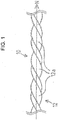
- Fig. 1 is a general view showing a example of a shaft of a guide Note that, in this figure, a length direction of the shaft is shortened to be schematically illustrated in whole in order to facilitate the understanding, thus providing an overall dimension different from the actual one.
- a shaft 10 takes on a rod-like body in an elongated shape.
- the shaft 10 can be formed using materials such as, for example, stainless steel (SUS304), a super elastic alloy such as an Ni-Ti alloy, and a piano wire, but not especially limited thereto.
- the shaft 10 is twisted in a predetermined direction along a longitudinal direction N, and has a helically shaped portion 12a. Additionally, the shaft 10 is provided with a plurality of grooves 12a at regular intervals along the longitudinal direction N. Thereby, for example, when inserting the shaft 10 into a blood vessel, the plurality of grooves 12a leads to reduction of contact areas with a blood vessel wall.
- the shaft 10 has the helically shaped portion 12, and thereby, when proximal side of the shaft 10 is rotated, such rotation is easily transmitted to a distal side of the shaft 10. That is, torque transmission characteristics are enhanced, resulting in improved operability.
- a direction of helix of the helically shaped portion 12 is counterclockwise along the longitudinal direction N of the shaft 10.
- the direction of helix of the helically shaped portion 12 is not limited thereto, and may be clockwise along the longitudinal direction N of the shaft 10.
- the shaft 10 has a cross section in an approximately rectangular shape in a direction vertical to the longitudinal direction N (hereinafter, simply referred to as a cross section). Further, the cross section has a projection 14 projected arcuately. In the present example, the projection 14 is provided only on one side among four sides forming the cross section. Moreover, the other three sides are linear portions 15 formed linearly.
- the shaft 10 has reduced contact parts with a blood vessel wall, while having a smaller load applied to the blood vessel wall in contact.
- a columnar metallic body is prepared to be rolled out from a predetermined direction.
- a rotary device is prepared, capable of applying rotary motion to a circumference of the metallic body having one end fixed, followed by rotation around a long axis of the metallic body from the other end.
- a distal end of the metallic body is fixed to one end of the rotary device while a proximal end of the metallic body is fixed to the other end of the rotary device, thereafter applying rotary motion from the other end of the rotary device, so that the metallic body is twisted from the proximal side.
- the shaft 10 is formed, including the helically shaped portion 12 twisted evenly along a longitudinal direction.
- the helically shaped portion 12 is twisted by the rotary device, and thereafter has stress applied by the twisting mitigated by means of heat treatment, thereby taking the form of a stable shape.
- a method of forming the helically shaped portion 12 is not limited to the above-described method, and may be fabricated by the other known method adopted appropriately.
- Fig. 3 is a cross-sectional view showing a first embodiment of the shaft of the present invention. Note that, in this figure, a cross section of the shaft is schematically illustrated, thus having a dimensional ratio different from the actual one.
- the projection 14 is provided only on one side among sides forming a cross section, and linear portions 15 are provided on the other sides.
- projections 24 are formed on a pair of sides facing each other. On sides except those having the pair of projections 24, linear portions 25 are provided, respectively.
- the shaft 20 of the present embodiment has surely reduced contact parts with a blood vessel wall, while having a further smaller load applied to the blood vessel wall in contact.
- Fig. 4 is a cross-sectional view showing a second embodiment of the shaft of the present invention. Note that, in this figure, a cross section of the shaft is schematically illustrated, thus having a dimensional ratio different from the actual one.
- the projections 24 are formed on a pair of sides facing each other, and the linear portions 25 are respectively provided on sides except those having the pair of the projections 24.
- recesses 37 recessed arcuately are provided, respectively.
- the radius of curvature of the projection 34 is set so as to be approximately the same as the radius of curvature of a virtual circle S having a diameter equivalent to a long axis X of the cross section.
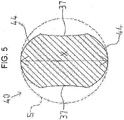
- Fig. 5 is a cross-sectional view showing a third embodiment of the shaft of the present invention. Note that, in this figure, a cross section of the shaft is schematically illustrated, thus having a dimensional ratio different from the actual one.
- the radius of curvature of the pair of the projections 34 is set so as to be approximately the same as the radius of curvature of the virtual circle S having a diameter equivalent to the long axis X of the cross section.
- the radius of curvature of a pair of projections 44 is smaller than the radius of curvature of the virtual circle S having a diameter equivalent to the long axis X of the cross section.
- Such the shaft 40 has a cross section in a tapered shape, and has two tops of respective projections 44 in contact with a blood vessel wall. Therefore, comparing to not only a configuration without a projection (a configuration having a cross-sectional rectangular shape whose four corners are in contact with a blood vessel wall) but also the second embodiment in which a projection is provided, having the radius of curvature approximately the same as the radius of curvature of the virtual circle S, in the shaft 40 of the present embodiment, contact areas (contact parts) with a blood vessel wall are more surely reduced.
- Fig. 6 is a general view showing a first embodiment of a guidewire of the present invention
- a distal side of the guidewire to be inserted into the body is provided on the left
- a proximal side of the guidewire to be operated by a manipulator such as a doctor is provided on the right.
- the guidewire is schematically illustrated, thus having a dimensional ratio different from the actual one.
- a guidewire 100 shown in Fig. 6 is used for treatment of the lower extremity vasculature by, for example, the Cross-Over method.
- the guidewire 100 includes a core shaft 110, and a coiled body 120 covering a circumference of a distal portion of the core shaft 110.
- the core shaft 110 includes a small diameter portion 110a, tapered portion 110b and a large diameter portion 110c in order from the distal side to the proximal side.
- the small diameter portion 110a is a part on the most distal side of the core shaft 110 and the most flexible part of the core shaft 110.
- the small diameter portion 110a is formed in a tabular shape by press working.
- the tapered portion 110b has a cross section formed in a tapered round shape whose diameter is gradually reduced toward the distal side. Note that, arrangements and dimensions of the small diameter portion 110a and the tapered portion 110b can be changed appropriately due to reasons to obtain desired rigidity and the like.
- the small diameter portion 110a may have a columnar shape. Further, the number of the tapered portions 110b and the angle of the tapered portion 110b may also be set appropriately as necessary.
- the large diameter portion 110c is located on a proximal side of the coiled body 120, and takes on a shape similar to that of the shaft in the above-described fourth embodiment. That is, the proximal side exposed from the coiled body 120 in the core shaft 110 is twisted along a longitudinal direction, and has a helically shaped portion 112. Moreover, as described in the second embodiment, a cross section of the helically shaped portion 112 has a pair of the projections 34 projected arcuately.
- the guidewire 100 of the present embodiment has surely reduced contact areas (contact parts) with a blood vessel wall. Accordingly, when the guidewire 100 rotates and enters the inside of a blood vessel, operation resistance of the guidewire 100 pushed and pulled is surely reduced so that sufficient torque transmission characteristics are secured, resulting in further enhanced operability. Furthermore, it is possible to surely reduce damage of a blood vessel.
- the large diameter portion 110c having the same shape as that of the shat of the above-described fourth embodiment is employed, however, the shape of the large diameter portion 110c is not limited thereto. That is, a large diameter portion may be employed having the same shape as that of the shaft of any one of the first to second embodiments. Even in this case, as with the present embodiment, operation resistance of the guidewire 100 pushed and pulled is surely reduced so that sufficient torque transmission characteristics are secured, resulting in further enhanced operability.
- the core shaft 110 can be formed using materials such as, for example, stainless steel (SUS304), a super elastic alloy such as an Ni-Ti alloy, and a piano wire, however, not especially limited thereto.
- SUS304 stainless steel
- a super elastic alloy such as an Ni-Ti alloy
- a piano wire however, not especially limited thereto.
- the coiled body 120 in the present embodiment is a single thread coil composed of wires wound helically.
- a distal end of the coiled body 120 is fixed a distal end of the core shaft 110 with a distal side joint 151.
- a proximal end of the coiled body 120 is fixed the core shaft 110 with a proximal side joint 153.
- an approximately middle part of the coiled body 120 located on a distal side from the proximal side joint 153 and on a proximal side from the distal side joint 151 is fixed the core shaft 110 with a middle joint 155.
- Materials forming the distal side joint 151, the proximal side joint 153 and the middle joint 155 are not especially limited, but include, for example, brazing metal such as an Sn-Pb alloy, a Pb-Ag alloy, an Sn-Ag alloy and an Au-Su alloy.
- Materials forming the coiled body 120 are not especially limited, but can employ a radiopaque wire or a radiolucent wire.
- Materials used for a radiopaque wire are not especially limited, but, for example, gold, platinum, tungsten, an alloy containing these elements (for example, a platinum-nickel alloy), or the like.
- materials used for a radiolucent wire are not especially limited, but can include, for example, stainless steel (SUS304, SUS316 and the like), a super elastic alloy such as an Ni-Ti alloy, a piano wire and the like can be used.
- Fig. 7 is a general view showing a second embodiment of a guidewire of the present invention.
- a distal side of the guidewire to be inserted into the body is provided on the left, and a proximal side of the guidewire to be operated by a manipulator such as a doctor is provided on the right.
- a manipulator such as a doctor
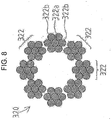
- a guidewire 200 of the present embodiment has a configuration of a coiled body different from that of the above-described fourth embodiment. That is, a coiled body 320 employed in the guidewire 200 of the present embodiment is composed of a plurality of strands 322 (eight strands in the present embodiment) wound helically, the strand 322 being made of a core wire (wire) 322a and six side lines (wires) 322b wound so as to cover a circumference of the core wire 322a.
- Materials forming the core wire 322a and the side line 322b are not especially limited, but include, for example, stainless steel, tungsten, an Ni-Ti alloy and the like.
- the guidewire 200 of the present embodiment comparing to a guidewire including a coiled body composed of, for example, a single wire having an external diameter nearly equal to that of the guidewire 200, flexibility of the coiled body is improved, thereby making it possible to secure sufficient torque transmission characteristics. Further, breaking strength against twisting is improved, so that safety of the guidewire 200 is enhanced.
Landscapes
- Health & Medical Sciences (AREA)
- Life Sciences & Earth Sciences (AREA)
- Biophysics (AREA)
- Pulmonology (AREA)
- Engineering & Computer Science (AREA)
- Anesthesiology (AREA)
- Biomedical Technology (AREA)
- Heart & Thoracic Surgery (AREA)
- Hematology (AREA)
- Animal Behavior & Ethology (AREA)
- General Health & Medical Sciences (AREA)
- Public Health (AREA)
- Veterinary Medicine (AREA)
- Media Introduction/Drainage Providing Device (AREA)
Claims (5)
- Schaft (20, 30, 40), der längs verdrillt ist und in einer Richtung quer zur Längsrichtung einen in etwa rechteckförmigen Querschnitt hat, dadurch gekennzeichnet, dass
der Querschnitt zwei Vorsprünge (24, 34, 44) aufweist, die in einer Richtung quer zur Längsrichtung bogenförmig vorspringen, und
die Vorsprünge (24, 34, 44) an zwei einander gegenüberliegenden Seiten der den Querschnitt formenden Seiten gebildet sind. - Schaft nach Anspruch 1, mit
Aussparungen (37), die an zwei einander gegenüberliegenden anderen Seiten als den Seiten mit den Vorsprüngen in der Richtung quer zur Längsrichtung bogenförmig ausgespart sind. - Schaft nach Anspruch 1 oder 2, wobei
der Krümmungsradius der Vorsprünge (44) kleiner ist als der Krümmungsradius eines virtuellen Kreises mit einem Durchmesser gleich einer Längsachse des Querschnitts. - Führungsdraht mit:einem Kernschaft (110) ; undeinem Wicklungskörper (120, 320), der einen distalen Abschnitt des Kernschafts umgibt, wobeiein auf einer proximalen Seite des Wicklungskörpers liegender proximaler Abschnitt (110c) des Kernschafts ein Schaft nach einem der Ansprüche 1 bis 3 ist.
- Führungsdraht nach Anspruch 4, wobei
der Wicklungskörper (320) aus einer Vielzahl von schraubenförmig gewickelten Strängen besteht, die jeweils aus einem Kerndraht und um den Umfang des Kerndrahts herum gewickelten Seitendrähten gebildet sind.
Applications Claiming Priority (1)
| Application Number | Priority Date | Filing Date | Title |
|---|---|---|---|
| JP2013207162A JP2015070896A (ja) | 2013-10-02 | 2013-10-02 | シャフト及びそのシャフトを用いたガイドワイヤ |
Publications (3)
| Publication Number | Publication Date |
|---|---|
| EP2857060A2 EP2857060A2 (de) | 2015-04-08 |
| EP2857060A3 EP2857060A3 (de) | 2015-04-15 |
| EP2857060B1 true EP2857060B1 (de) | 2017-02-22 |
Family
ID=50979694
Family Applications (1)
| Application Number | Title | Priority Date | Filing Date |
|---|---|---|---|
| EP14173744.5A Active EP2857060B1 (de) | 2013-10-02 | 2014-06-24 | Schaft und Führungsdraht damit |
Country Status (4)
| Country | Link |
|---|---|
| US (1) | US9259557B2 (de) |
| EP (1) | EP2857060B1 (de) |
| JP (1) | JP2015070896A (de) |
| CN (1) | CN104511081A (de) |
Families Citing this family (3)
| Publication number | Priority date | Publication date | Assignee | Title |
|---|---|---|---|---|
| JP2015070896A (ja) | 2013-10-02 | 2015-04-16 | 朝日インテック株式会社 | シャフト及びそのシャフトを用いたガイドワイヤ |
| JP5896480B2 (ja) | 2013-10-02 | 2016-03-30 | 朝日インテック株式会社 | ガイドワイヤ |
| JP6061341B2 (ja) | 2013-12-06 | 2017-01-18 | 朝日インテック株式会社 | ガイドワイヤ |
Citations (1)
| Publication number | Priority date | Publication date | Assignee | Title |
|---|---|---|---|---|
| WO2012172881A1 (ja) * | 2011-06-13 | 2012-12-20 | 日星電気株式会社 | ガイドワイヤのための樹脂製チューブ、ガイドワイヤのための樹脂製チューブの製造方法及びガイドワイヤ |
Family Cites Families (16)
| Publication number | Priority date | Publication date | Assignee | Title |
|---|---|---|---|---|
| US5313967A (en) * | 1992-07-24 | 1994-05-24 | Medtronic, Inc. | Helical guidewire |
| US5299580A (en) * | 1992-10-09 | 1994-04-05 | Scimed Life Systems, Inc. | Guidewire with safety ribbon with substantially axially symmetric flexibility |
| DE69707789T2 (de) | 1996-08-28 | 2002-05-02 | Asahi Intecc Co., Ltd. | Führungsdraht |
| US6059771A (en) | 1996-12-23 | 2000-05-09 | Johnson & Johnson Medical, Inc. | Stiffening member to increase fluid flow within a medical device |
| US20020043118A1 (en) | 2000-06-23 | 2002-04-18 | Claude Timothy J. | Guidewire device and method |
| US8113916B2 (en) * | 2003-01-17 | 2012-02-14 | Boston Scientific Scimed, Inc. | Straightening and centerless grinding of wire for use with medical devices |
| WO2004093655A2 (en) * | 2003-04-23 | 2004-11-04 | Applied Medical Resources Corporation | Helical guidewire |
| JP5067845B2 (ja) * | 2007-06-22 | 2012-11-07 | 朝日インテック株式会社 | 医療用ガイドワイヤ |
| EP2163276A4 (de) * | 2007-06-29 | 2011-04-27 | Piolax Medical Devices Inc | Führungsdraht |
| JP4609904B2 (ja) * | 2008-03-24 | 2011-01-12 | 朝日インテック株式会社 | 医療用ガイドワイヤ |
| JP5628515B2 (ja) | 2009-12-18 | 2014-11-19 | 株式会社パイオラックスメディカルデバイス | ガイドワイヤ |
| JP5392787B2 (ja) | 2010-09-28 | 2014-01-22 | 朝日インテック株式会社 | ガイドワイヤ |
| JP5645221B2 (ja) | 2011-10-20 | 2014-12-24 | 朝日インテック株式会社 | ガイドワイヤ |
| US20130304108A1 (en) | 2012-05-08 | 2013-11-14 | Daniel C. Weber | Systems and apparatus for treating blood vessels and related methods |
| JP2015070896A (ja) | 2013-10-02 | 2015-04-16 | 朝日インテック株式会社 | シャフト及びそのシャフトを用いたガイドワイヤ |
| JP5896480B2 (ja) | 2013-10-02 | 2016-03-30 | 朝日インテック株式会社 | ガイドワイヤ |
-
2013
- 2013-10-02 JP JP2013207162A patent/JP2015070896A/ja active Pending
-
2014
- 2014-06-05 CN CN201410247309.0A patent/CN104511081A/zh active Pending
- 2014-06-24 EP EP14173744.5A patent/EP2857060B1/de active Active
- 2014-06-26 US US14/315,990 patent/US9259557B2/en active Active
Patent Citations (1)
| Publication number | Priority date | Publication date | Assignee | Title |
|---|---|---|---|---|
| WO2012172881A1 (ja) * | 2011-06-13 | 2012-12-20 | 日星電気株式会社 | ガイドワイヤのための樹脂製チューブ、ガイドワイヤのための樹脂製チューブの製造方法及びガイドワイヤ |
Also Published As
| Publication number | Publication date |
|---|---|
| US9259557B2 (en) | 2016-02-16 |
| US20150094691A1 (en) | 2015-04-02 |
| CN104511081A (zh) | 2015-04-15 |
| EP2857060A2 (de) | 2015-04-08 |
| JP2015070896A (ja) | 2015-04-16 |
| EP2857060A3 (de) | 2015-04-15 |
Similar Documents
| Publication | Publication Date | Title |
|---|---|---|
| EP2881136B1 (de) | Führungsdraht | |
| US8608670B2 (en) | Guidewire | |
| US8622932B2 (en) | Guidewire | |
| EP2962718A1 (de) | Führungsdraht | |
| JP5142229B2 (ja) | ガイドワイヤ | |
| JP5240948B2 (ja) | ガイドワイヤ | |
| JP2012034967A (ja) | ガイドワイヤ | |
| EP2921195A1 (de) | Führungsdraht | |
| EP2937109B1 (de) | Führungsdraht | |
| EP3072549A1 (de) | Katheter | |
| JP6405274B2 (ja) | ガイドワイヤ | |
| EP2857060B1 (de) | Schaft und Führungsdraht damit | |
| EP2857061B1 (de) | Welle und Führungsdraht damit | |
| JP7050175B2 (ja) | 医療機器 | |
| EP2896426B1 (de) | Litzendraht und Führungsdraht damit | |
| JP2013162920A (ja) | ガイドワイヤ | |
| JP2017070803A (ja) | ガイドワイヤ | |
| JP2013208351A (ja) | ガイドワイヤ |
Legal Events
| Date | Code | Title | Description |
|---|---|---|---|
| PUAL | Search report despatched |
Free format text: ORIGINAL CODE: 0009013 |
|
| PUAI | Public reference made under article 153(3) epc to a published international application that has entered the european phase |
Free format text: ORIGINAL CODE: 0009012 |
|
| 17P | Request for examination filed |
Effective date: 20140624 |
|
| AK | Designated contracting states |
Kind code of ref document: A2 Designated state(s): AL AT BE BG CH CY CZ DE DK EE ES FI FR GB GR HR HU IE IS IT LI LT LU LV MC MK MT NL NO PL PT RO RS SE SI SK SM TR |
|
| AX | Request for extension of the european patent |
Extension state: BA ME |
|
| AK | Designated contracting states |
Kind code of ref document: A3 Designated state(s): AL AT BE BG CH CY CZ DE DK EE ES FI FR GB GR HR HU IE IS IT LI LT LU LV MC MK MT NL NO PL PT RO RS SE SI SK SM TR |
|
| AX | Request for extension of the european patent |
Extension state: BA ME |
|
| RIC1 | Information provided on ipc code assigned before grant |
Ipc: A61M 25/09 20060101AFI20150306BHEP Ipc: B21F 7/00 20060101ALI20150306BHEP |
|
| R17P | Request for examination filed (corrected) |
Effective date: 20150929 |
|
| RBV | Designated contracting states (corrected) |
Designated state(s): AL AT BE BG CH CY CZ DE DK EE ES FI FR GB GR HR HU IE IS IT LI LT LU LV MC MK MT NL NO PL PT RO RS SE SI SK SM TR |
|
| 17Q | First examination report despatched |
Effective date: 20160120 |
|
| GRAP | Despatch of communication of intention to grant a patent |
Free format text: ORIGINAL CODE: EPIDOSNIGR1 |
|
| INTG | Intention to grant announced |
Effective date: 20160706 |
|
| GRAJ | Information related to disapproval of communication of intention to grant by the applicant or resumption of examination proceedings by the epo deleted |
Free format text: ORIGINAL CODE: EPIDOSDIGR1 |
|
| GRAS | Grant fee paid |
Free format text: ORIGINAL CODE: EPIDOSNIGR3 |
|
| INTC | Intention to grant announced (deleted) | ||
| GRAP | Despatch of communication of intention to grant a patent |
Free format text: ORIGINAL CODE: EPIDOSNIGR1 |
|
| INTG | Intention to grant announced |
Effective date: 20161223 |
|
| GRAA | (expected) grant |
Free format text: ORIGINAL CODE: 0009210 |
|
| AK | Designated contracting states |
Kind code of ref document: B1 Designated state(s): AL AT BE BG CH CY CZ DE DK EE ES FI FR GB GR HR HU IE IS IT LI LT LU LV MC MK MT NL NO PL PT RO RS SE SI SK SM TR |
|
| REG | Reference to a national code |
Ref country code: GB Ref legal event code: FG4D |
|
| REG | Reference to a national code |
Ref country code: CH Ref legal event code: EP |
|
| REG | Reference to a national code |
Ref country code: AT Ref legal event code: REF Ref document number: 868792 Country of ref document: AT Kind code of ref document: T Effective date: 20170315 |
|
| REG | Reference to a national code |
Ref country code: IE Ref legal event code: FG4D |
|
| REG | Reference to a national code |
Ref country code: DE Ref legal event code: R096 Ref document number: 602014006863 Country of ref document: DE |
|
| REG | Reference to a national code |
Ref country code: LT Ref legal event code: MG4D |
|
| REG | Reference to a national code |
Ref country code: NL Ref legal event code: MP Effective date: 20170222 |
|
| REG | Reference to a national code |
Ref country code: AT Ref legal event code: MK05 Ref document number: 868792 Country of ref document: AT Kind code of ref document: T Effective date: 20170222 |
|
| PG25 | Lapsed in a contracting state [announced via postgrant information from national office to epo] |
Ref country code: HR Free format text: LAPSE BECAUSE OF FAILURE TO SUBMIT A TRANSLATION OF THE DESCRIPTION OR TO PAY THE FEE WITHIN THE PRESCRIBED TIME-LIMIT Effective date: 20170222 Ref country code: GR Free format text: LAPSE BECAUSE OF FAILURE TO SUBMIT A TRANSLATION OF THE DESCRIPTION OR TO PAY THE FEE WITHIN THE PRESCRIBED TIME-LIMIT Effective date: 20170523 Ref country code: NO Free format text: LAPSE BECAUSE OF FAILURE TO SUBMIT A TRANSLATION OF THE DESCRIPTION OR TO PAY THE FEE WITHIN THE PRESCRIBED TIME-LIMIT Effective date: 20170522 Ref country code: LT Free format text: LAPSE BECAUSE OF FAILURE TO SUBMIT A TRANSLATION OF THE DESCRIPTION OR TO PAY THE FEE WITHIN THE PRESCRIBED TIME-LIMIT Effective date: 20170222 Ref country code: FI Free format text: LAPSE BECAUSE OF FAILURE TO SUBMIT A TRANSLATION OF THE DESCRIPTION OR TO PAY THE FEE WITHIN THE PRESCRIBED TIME-LIMIT Effective date: 20170222 |
|
| PG25 | Lapsed in a contracting state [announced via postgrant information from national office to epo] |
Ref country code: SE Free format text: LAPSE BECAUSE OF FAILURE TO SUBMIT A TRANSLATION OF THE DESCRIPTION OR TO PAY THE FEE WITHIN THE PRESCRIBED TIME-LIMIT Effective date: 20170222 Ref country code: LV Free format text: LAPSE BECAUSE OF FAILURE TO SUBMIT A TRANSLATION OF THE DESCRIPTION OR TO PAY THE FEE WITHIN THE PRESCRIBED TIME-LIMIT Effective date: 20170222 Ref country code: BG Free format text: LAPSE BECAUSE OF FAILURE TO SUBMIT A TRANSLATION OF THE DESCRIPTION OR TO PAY THE FEE WITHIN THE PRESCRIBED TIME-LIMIT Effective date: 20170522 Ref country code: AT Free format text: LAPSE BECAUSE OF FAILURE TO SUBMIT A TRANSLATION OF THE DESCRIPTION OR TO PAY THE FEE WITHIN THE PRESCRIBED TIME-LIMIT Effective date: 20170222 Ref country code: RS Free format text: LAPSE BECAUSE OF FAILURE TO SUBMIT A TRANSLATION OF THE DESCRIPTION OR TO PAY THE FEE WITHIN THE PRESCRIBED TIME-LIMIT Effective date: 20170222 Ref country code: PT Free format text: LAPSE BECAUSE OF FAILURE TO SUBMIT A TRANSLATION OF THE DESCRIPTION OR TO PAY THE FEE WITHIN THE PRESCRIBED TIME-LIMIT Effective date: 20170622 Ref country code: ES Free format text: LAPSE BECAUSE OF FAILURE TO SUBMIT A TRANSLATION OF THE DESCRIPTION OR TO PAY THE FEE WITHIN THE PRESCRIBED TIME-LIMIT Effective date: 20170222 Ref country code: NL Free format text: LAPSE BECAUSE OF FAILURE TO SUBMIT A TRANSLATION OF THE DESCRIPTION OR TO PAY THE FEE WITHIN THE PRESCRIBED TIME-LIMIT Effective date: 20170222 |
|
| PG25 | Lapsed in a contracting state [announced via postgrant information from national office to epo] |
Ref country code: CZ Free format text: LAPSE BECAUSE OF FAILURE TO SUBMIT A TRANSLATION OF THE DESCRIPTION OR TO PAY THE FEE WITHIN THE PRESCRIBED TIME-LIMIT Effective date: 20170222 Ref country code: SK Free format text: LAPSE BECAUSE OF FAILURE TO SUBMIT A TRANSLATION OF THE DESCRIPTION OR TO PAY THE FEE WITHIN THE PRESCRIBED TIME-LIMIT Effective date: 20170222 Ref country code: EE Free format text: LAPSE BECAUSE OF FAILURE TO SUBMIT A TRANSLATION OF THE DESCRIPTION OR TO PAY THE FEE WITHIN THE PRESCRIBED TIME-LIMIT Effective date: 20170222 Ref country code: RO Free format text: LAPSE BECAUSE OF FAILURE TO SUBMIT A TRANSLATION OF THE DESCRIPTION OR TO PAY THE FEE WITHIN THE PRESCRIBED TIME-LIMIT Effective date: 20170222 Ref country code: IT Free format text: LAPSE BECAUSE OF FAILURE TO SUBMIT A TRANSLATION OF THE DESCRIPTION OR TO PAY THE FEE WITHIN THE PRESCRIBED TIME-LIMIT Effective date: 20170222 |
|
| REG | Reference to a national code |
Ref country code: DE Ref legal event code: R097 Ref document number: 602014006863 Country of ref document: DE |
|
| PG25 | Lapsed in a contracting state [announced via postgrant information from national office to epo] |
Ref country code: PL Free format text: LAPSE BECAUSE OF FAILURE TO SUBMIT A TRANSLATION OF THE DESCRIPTION OR TO PAY THE FEE WITHIN THE PRESCRIBED TIME-LIMIT Effective date: 20170222 Ref country code: SM Free format text: LAPSE BECAUSE OF FAILURE TO SUBMIT A TRANSLATION OF THE DESCRIPTION OR TO PAY THE FEE WITHIN THE PRESCRIBED TIME-LIMIT Effective date: 20170222 Ref country code: DK Free format text: LAPSE BECAUSE OF FAILURE TO SUBMIT A TRANSLATION OF THE DESCRIPTION OR TO PAY THE FEE WITHIN THE PRESCRIBED TIME-LIMIT Effective date: 20170222 |
|
| PLBE | No opposition filed within time limit |
Free format text: ORIGINAL CODE: 0009261 |
|
| STAA | Information on the status of an ep patent application or granted ep patent |
Free format text: STATUS: NO OPPOSITION FILED WITHIN TIME LIMIT |
|
| 26N | No opposition filed |
Effective date: 20171123 |
|
| PG25 | Lapsed in a contracting state [announced via postgrant information from national office to epo] |
Ref country code: MC Free format text: LAPSE BECAUSE OF FAILURE TO SUBMIT A TRANSLATION OF THE DESCRIPTION OR TO PAY THE FEE WITHIN THE PRESCRIBED TIME-LIMIT Effective date: 20170222 |
|
| REG | Reference to a national code |
Ref country code: CH Ref legal event code: PL |
|
| PG25 | Lapsed in a contracting state [announced via postgrant information from national office to epo] |
Ref country code: SI Free format text: LAPSE BECAUSE OF FAILURE TO SUBMIT A TRANSLATION OF THE DESCRIPTION OR TO PAY THE FEE WITHIN THE PRESCRIBED TIME-LIMIT Effective date: 20170222 |
|
| REG | Reference to a national code |
Ref country code: IE Ref legal event code: MM4A |
|
| REG | Reference to a national code |
Ref country code: FR Ref legal event code: ST Effective date: 20180228 |
|
| PG25 | Lapsed in a contracting state [announced via postgrant information from national office to epo] |
Ref country code: LU Free format text: LAPSE BECAUSE OF NON-PAYMENT OF DUE FEES Effective date: 20170624 Ref country code: IE Free format text: LAPSE BECAUSE OF NON-PAYMENT OF DUE FEES Effective date: 20170624 Ref country code: LI Free format text: LAPSE BECAUSE OF NON-PAYMENT OF DUE FEES Effective date: 20170630 Ref country code: CH Free format text: LAPSE BECAUSE OF NON-PAYMENT OF DUE FEES Effective date: 20170630 |
|
| PG25 | Lapsed in a contracting state [announced via postgrant information from national office to epo] |
Ref country code: FR Free format text: LAPSE BECAUSE OF NON-PAYMENT OF DUE FEES Effective date: 20170630 |
|
| REG | Reference to a national code |
Ref country code: BE Ref legal event code: MM Effective date: 20170630 |
|
| PG25 | Lapsed in a contracting state [announced via postgrant information from national office to epo] |
Ref country code: BE Free format text: LAPSE BECAUSE OF NON-PAYMENT OF DUE FEES Effective date: 20170630 |
|
| PG25 | Lapsed in a contracting state [announced via postgrant information from national office to epo] |
Ref country code: MT Free format text: LAPSE BECAUSE OF NON-PAYMENT OF DUE FEES Effective date: 20170624 |
|
| PG25 | Lapsed in a contracting state [announced via postgrant information from national office to epo] |
Ref country code: HU Free format text: LAPSE BECAUSE OF FAILURE TO SUBMIT A TRANSLATION OF THE DESCRIPTION OR TO PAY THE FEE WITHIN THE PRESCRIBED TIME-LIMIT; INVALID AB INITIO Effective date: 20140624 |
|
| PG25 | Lapsed in a contracting state [announced via postgrant information from national office to epo] |
Ref country code: CY Free format text: LAPSE BECAUSE OF FAILURE TO SUBMIT A TRANSLATION OF THE DESCRIPTION OR TO PAY THE FEE WITHIN THE PRESCRIBED TIME-LIMIT Effective date: 20170222 |
|
| PG25 | Lapsed in a contracting state [announced via postgrant information from national office to epo] |
Ref country code: MK Free format text: LAPSE BECAUSE OF FAILURE TO SUBMIT A TRANSLATION OF THE DESCRIPTION OR TO PAY THE FEE WITHIN THE PRESCRIBED TIME-LIMIT Effective date: 20170222 |
|
| PG25 | Lapsed in a contracting state [announced via postgrant information from national office to epo] |
Ref country code: TR Free format text: LAPSE BECAUSE OF FAILURE TO SUBMIT A TRANSLATION OF THE DESCRIPTION OR TO PAY THE FEE WITHIN THE PRESCRIBED TIME-LIMIT Effective date: 20170222 |
|
| PG25 | Lapsed in a contracting state [announced via postgrant information from national office to epo] |
Ref country code: AL Free format text: LAPSE BECAUSE OF FAILURE TO SUBMIT A TRANSLATION OF THE DESCRIPTION OR TO PAY THE FEE WITHIN THE PRESCRIBED TIME-LIMIT Effective date: 20170222 Ref country code: IS Free format text: LAPSE BECAUSE OF FAILURE TO SUBMIT A TRANSLATION OF THE DESCRIPTION OR TO PAY THE FEE WITHIN THE PRESCRIBED TIME-LIMIT Effective date: 20170622 |
|
| PGFP | Annual fee paid to national office [announced via postgrant information from national office to epo] |
Ref country code: DE Payment date: 20250618 Year of fee payment: 12 |
|
| PGFP | Annual fee paid to national office [announced via postgrant information from national office to epo] |
Ref country code: GB Payment date: 20250618 Year of fee payment: 12 |