EP2857082A1 - Installation de filtration dotée d'un nettoyage à régulation automatique - Google Patents
Installation de filtration dotée d'un nettoyage à régulation automatique Download PDFInfo
- Publication number
- EP2857082A1 EP2857082A1 EP13187103.0A EP13187103A EP2857082A1 EP 2857082 A1 EP2857082 A1 EP 2857082A1 EP 13187103 A EP13187103 A EP 13187103A EP 2857082 A1 EP2857082 A1 EP 2857082A1
- Authority
- EP
- European Patent Office
- Prior art keywords
- pressure
- filter
- control unit
- differential pressure
- cleaning
- Prior art date
- Legal status (The legal status is an assumption and is not a legal conclusion. Google has not performed a legal analysis and makes no representation as to the accuracy of the status listed.)
- Withdrawn
Links
- 238000004140 cleaning Methods 0.000 title claims abstract description 100
- 238000010926 purge Methods 0.000 claims description 35
- 230000002040 relaxant effect Effects 0.000 claims description 4
- 238000000746 purification Methods 0.000 claims 1
- 230000001419 dependent effect Effects 0.000 abstract description 4
- 239000012530 fluid Substances 0.000 description 14
- 238000000034 method Methods 0.000 description 7
- IJGRMHOSHXDMSA-UHFFFAOYSA-N Atomic nitrogen Chemical compound N#N IJGRMHOSHXDMSA-UHFFFAOYSA-N 0.000 description 6
- 239000012528 membrane Substances 0.000 description 6
- 239000002817 coal dust Substances 0.000 description 5
- 239000007789 gas Substances 0.000 description 5
- 239000012065 filter cake Substances 0.000 description 4
- 238000011109 contamination Methods 0.000 description 3
- 239000000428 dust Substances 0.000 description 3
- 229910052757 nitrogen Inorganic materials 0.000 description 3
- 230000007423 decrease Effects 0.000 description 2
- 239000012535 impurity Substances 0.000 description 2
- 230000001105 regulatory effect Effects 0.000 description 2
- 230000006978 adaptation Effects 0.000 description 1
- 230000005540 biological transmission Effects 0.000 description 1
- 239000003245 coal Substances 0.000 description 1
- 238000010276 construction Methods 0.000 description 1
- 239000000356 contaminant Substances 0.000 description 1
- 238000001514 detection method Methods 0.000 description 1
- 238000007599 discharging Methods 0.000 description 1
- 238000001914 filtration Methods 0.000 description 1
- 230000006266 hibernation Effects 0.000 description 1
- 239000011261 inert gas Substances 0.000 description 1
- 238000002347 injection Methods 0.000 description 1
- 239000007924 injection Substances 0.000 description 1
- 230000003993 interaction Effects 0.000 description 1
- 230000007257 malfunction Effects 0.000 description 1
- 238000004519 manufacturing process Methods 0.000 description 1
- 238000005259 measurement Methods 0.000 description 1
- 230000010355 oscillation Effects 0.000 description 1
- 239000002245 particle Substances 0.000 description 1
- 238000010079 rubber tapping Methods 0.000 description 1
- 238000005201 scrubbing Methods 0.000 description 1
- 239000000243 solution Substances 0.000 description 1
Images
Classifications
-
- B—PERFORMING OPERATIONS; TRANSPORTING
- B01—PHYSICAL OR CHEMICAL PROCESSES OR APPARATUS IN GENERAL
- B01D—SEPARATION
- B01D46/00—Filters or filtering processes specially modified for separating dispersed particles from gases or vapours
- B01D46/42—Auxiliary equipment or operation thereof
- B01D46/44—Auxiliary equipment or operation thereof controlling filtration
- B01D46/446—Auxiliary equipment or operation thereof controlling filtration by pressure measuring
-
- B—PERFORMING OPERATIONS; TRANSPORTING
- B01—PHYSICAL OR CHEMICAL PROCESSES OR APPARATUS IN GENERAL
- B01D—SEPARATION
- B01D46/00—Filters or filtering processes specially modified for separating dispersed particles from gases or vapours
- B01D46/66—Regeneration of the filtering material or filter elements inside the filter
- B01D46/70—Regeneration of the filtering material or filter elements inside the filter by acting counter-currently on the filtering surface, e.g. by flushing on the non-cake side of the filter
- B01D46/71—Regeneration of the filtering material or filter elements inside the filter by acting counter-currently on the filtering surface, e.g. by flushing on the non-cake side of the filter with pressurised gas, e.g. pulsed air
-
- B—PERFORMING OPERATIONS; TRANSPORTING
- B01—PHYSICAL OR CHEMICAL PROCESSES OR APPARATUS IN GENERAL
- B01D—SEPARATION
- B01D46/00—Filters or filtering processes specially modified for separating dispersed particles from gases or vapours
- B01D46/02—Particle separators, e.g. dust precipitators, having hollow filters made of flexible material
-
- B—PERFORMING OPERATIONS; TRANSPORTING
- B01—PHYSICAL OR CHEMICAL PROCESSES OR APPARATUS IN GENERAL
- B01D—SEPARATION
- B01D41/00—Regeneration of the filtering material or filter elements outside the filter for liquid or gaseous fluids
-
- B—PERFORMING OPERATIONS; TRANSPORTING
- B01—PHYSICAL OR CHEMICAL PROCESSES OR APPARATUS IN GENERAL
- B01D—SEPARATION
- B01D46/00—Filters or filtering processes specially modified for separating dispersed particles from gases or vapours
- B01D46/02—Particle separators, e.g. dust precipitators, having hollow filters made of flexible material
- B01D46/04—Cleaning filters
Definitions
- the present invention generally relates to a filter system with a self-regulating cleaning.
- the invention is particularly suitable for cleaning a filter system, which is used for cleaning of transmission vessels in the field of coal dust injection.
- coal dust is compressed with nitrogen to a predetermined pressure. If the predetermined pressure is reached, the coal dust is pneumatically transported with the nitrogen from the sending vessel until no longer sufficient coal dust is present in the sending vessel.
- the pressure of the transmitter vessel is adjusted to the ambient pressure. When decompressing the remaining coal dust in the sending vessel may not reach the atmosphere. Therefore, the deflated air is redirected to a filter system in which several filter bags are arranged.
- the dusty filter bags can be cleaned with a cleaning according to the invention during the relaxation.
- Filter systems are used in numerous industrial processes and are basically used for cleaning / dedusting a fluid flow, which is passed through such filter systems.
- the filter systems usually have a plurality of filter bags, which free the fluid flowing through of impurities, such as dust particles.
- impurities such as dust particles.
- the fluid flow from outside to inside is passed through the filter bags, so that the contaminants settle on the outside of the filter bags. After a certain period of operation, the filter bags are dirty and must be cleaned.
- the filters were cleaned by shaking or tapping by motorized or manually operated vibrators. With the help of such methods, the filter bags are set in vibration and the filter cake dissolves due to these movements of the outer surface of the filter. However, the mechanical cleaning has a high stress on the filter tubing result, which is why their life shortened.
- the overpressure with which the Abcurismedium is provided. If the overpressure of the cleaning pressure is selected too high compared with the filter pressure, the service life of the bag filter is reduced. In the worst case, even the bag filter can be destroyed by too high pressure. However, if the overpressure is not selected to be sufficiently high, the bag filter will not be efficiently cleaned. As a result, the purge pressure is regulated to be within a predetermined range from the filter pressure, so that the purge pressure is sufficient to effectively and gently clean the bag filter.
- the U.S. Pat. No. 5,837,017 describes a cleaning device which detects the differential pressure between the "clean side” of the bag filter and the "dirty side” of the bag filter with pressure sensors.
- the cleaning device in US 5,837,017 is based on the assumption that the Contamination of the bag filter is dependent on the size of the measured pressure difference between the "clean side” and "dirty side". If the size of the measured pressure difference has reached a certain threshold value, the control unit recognizes that the filter is clogged and opens a pressure valve, which supplies the cleaning nozzles with cleaning air.
- the pressure valve is controlled by the control unit so that the purge pressure is adjusted to the pressure difference in the filter. Accordingly, the purge pressure is adjusted to the degree of soiling.
- both the pressure on the "clean side” and on the "dirty side” with the aid of pressure sensors are measured and passed on to a control unit.
- the system controls the cleaning via the differential pressures and not the absolute pressures. If the filter pressure increases, for example due to external influences, the bag filter can no longer be cleaned because the required cleaning pressure can no longer be provided.
- An object of the present invention is to provide a filter system which enables reliable provision of a purge pressure pT for cleaning the filter bags at a variable filter pressure. This object is achieved by a cleaning system according to claim 1.
- the filter system comprises a gas feed, wherein in a preferred embodiment of the invention is a compressed air supply, which supplies the filter system with a cleaning medium with a constant feed pressure pN.
- the filter system comprises a cleaning tank, which is fed by the gas supply and in which the cleaning medium is stored with a variable cleaning pressure pT, where pN ⁇ pT.
- the filter system also includes a pressure filter with a filter pressure pF. The pressure filter is cleaned cyclically at predetermined time intervals or differential pressure-dependent from the cleaning medium from the cleaning tank.
- the filter system has a control loop which comprises a first differential pressure regulator and a first control unit. The first differential pressure regulator is disposed between the gas supply and the purge tank.
- the first control unit actuates the first differential pressure controller at a lower pressure difference.
- the control circuit comprises a second differential pressure regulator and a second control unit.
- the second differential pressure regulator is arranged in the discharge line of the cleaning tank.
- the discharge line is preferably arranged between the cleaning tank and the pressure filter.
- the second control unit actuates the second differential pressure regulator at an upper pressure difference.
- the control unit also includes a positive conduction and a negative conduction.
- the positive conduction fluid connects the first control unit with the second control unit and the Abcuristank.
- the negative effective line fluid connects the first control unit with the second control unit and the pressure filter.
- the purge pressure pT is provided with an overpressure relative to the filter pressure pN in the purge tank and is applied to the first control unit and the second control unit.
- the first control unit actuates the first differential pressure regulator when the overpressure is below the lower pressure differential.
- the second control unit actuates the second differential pressure regulator when the overpressure is above the upper pressure differential.
- the filter system provides the appropriate Ab mecanics für at any time, without even a sensor is in the pressure filter. Even with a variation of the filter pressure pF, the filter system reliably regulates and adapts the cleaning pressure pT so that a reliable filter cleaning is guaranteed.
- the patent describes only a change in Abcurisstroms due to the strength of the contamination of the filter, the change is performed by a control valve increases the filter pressure, for example, by external influences, as is the case for example when relaxing the transmitting vessels, is not known as the cleaning device in US 5,837,017 responds to these influences, since the system is not designed for such pressure fluctuations ..
- the filter system according to the invention is particularly reliable and independent of external influences due to the fluid connection between the control units. Especially in this field of application, where many impurities are virtually "collected” false measurements, disturbances and failure of sensors almost provoked. Since in the filter system according to the invention no sensors are needed to ensure a self-regulation of Ablitisstiks compared to the filter pressure, the filter system according to the invention is particularly reliable.
- the filter system ensures that a fluctuating operating pressure pF (filter pressure) always ensures a predetermined overpressure between the pressure filter and the cleaning tank.
- pF fluctuating operating pressure
- the purge pressure in the purge tank is readjusted by the control unit, so that the pressure difference between the purge tank and the pressure filter is in the predetermined pressure range.
- the first control unit comprises a first spring with which the lower pressure difference can be adjusted.
- a first diaphragm is arranged, which separates a first positive pressure chamber from a first negative pressure chamber.
- the first spring may be adjusted by a first biasing means so that the first spring exerts a first spring pressure on the first diaphragm.
- the second control unit may comprise a second spring with which the upper pressure difference can be adjusted.
- a second membrane is arranged in the second control unit, which separates a second positive pressure chamber from a second negative pressure chamber.
- the second spring may be locked by a second biasing means so that the second spring exerts a second spring pressure on the second diaphragm.
- the first biasing means and the second biasing means may be manually adjusted or electronically controlled.
- the first spring and the second spring allow adjustment of the first and the second pressure difference.
- the range of the overpressure with which the purge pressure is to be provided opposite to the pressure filter can be adjusted.
- the first differential pressure regulator is mechanically coupled to the first control unit and / or the second differential pressure regulator is mechanically coupled to the second control unit.
- the differential pressure controllers can control the first pressure difference and / or the second pressure difference.
- the first differential pressure regulator may be electronically coupled to the first control unit and / or the second differential pressure regulator may be electronically coupled to the second control unit. This results in the advantage that the control units do not have to be arranged in the immediate vicinity of the differential pressure regulators.
- the first differential pressure regulator is preferably open in the idle state and the second differential pressure regulator is closed in the idle state.
- control circuit comprises at least one flow rate limiter, which are mounted in the negative and / or positive conduction line.
- the filter system is preferably used in Kohlestaubeinblasanlagen for cleaning the filter of transmitting vessels. Both when relaxing and when compressing the transmitter vessel, the filters should be able to be cleaned.
- the filter system according to the invention is used.
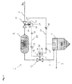
- Fig. 1 a schematic representation of a preferred filter assembly.
- FIG. 1 the construction of a filter system 2 is shown, which operates under fluctuating operating pressure.
- the filter unit 2 is used as a top filter of the transmitting vessel for coal, whereby the filter pressure pF changes during operation.
- the filters should be able to be cleaned both when relaxing the pressure in the sending vessel and when compressing the pressure in the sending vessel.
- the purge pressure pT is carried along with the filter pressure pF.
- the filter unit 2 is equipped with filter bags and a Pulse-Jet cleaning system, which cleans the filter bags either differential pressure-dependent or cyclically.
- a cleaning pressure pT is provided for cleaning the filter, which is above the operating pressure pF (which is also referred to as filter pressure pF) of the pressure filter 4. If the cleaning pressure pT of the filter system 2 is too low compared with the filter pressure pF, the filter cake can not be completely or completely detached from the tube filters. For cleaning, the cleaning medium is therefore provided with an overpressure relative to the filter pressure pF. Is the overpressure of Filter system 2 too high, this can result in extreme cases destroying the filter bags. As a rule, too much overpressure shortens the service life of the filter bags. As a result, it will be ensured that the overpressure of the purge pressure pT with respect to the filter pressure pF is within a certain pressure range.
- the filter system in Fig.1 has a pressure filter 4 for filtering the dirt.
- the air to be filtered is passed from outside to inside through the filter bags to be cleaned.
- a cleaning medium for cleaning the bag filter both air, nitrogen and another inert gas can be used.
- compressed air is used to clean the filter.
- the compressed air is provided at a feed pressure PN at the compressed air supply 6.
- the feed pressure pN is selected to exceed the purge pressure pT of the purge medium in the purge tank 8.
- the compressed air supply has a first differential pressure regulator 10, which is arranged between the cleaning tank 8 and the compressed air feed 6 and regulates a fluid flow between the compressed air feed 6 and the cleaning tank 8.
- the discharge line 7 from the cleaning tank 8 to the pressure filter 4 has a second differential pressure regulator 12, which discharges compressed air from the cleaning tank 8 via the pressure filter 4 or the pressure filter line 9 when an upper pressure difference between the cleaning tank 8 and the pressure filter 4 is exceeded.
- the pressure filter line 9 carries only clean gas, which it is mounted on the clean side of the pressure filter.
- the first differential pressure regulator 10 has a first control unit 14, which controls the opening and closing of the first differential pressure regulator 10. Opening the first differential pressure regulator 10 fills the cleaning tank 8 with the cleaning medium, which leads to an increase of the cleaning pressure pT in the cleaning tank 8. Closing of the first differential pressure regulator 10 results in no fluid connection between the cleaning tank 8 and the compressed air supply 6. At rest, the first differential pressure regulator 10 is opened to ensure that the Abcuristank 8 is supplied with air and in the control units 14, 16, a first air pressure is provided. The second differential pressure regulator 12 is closed to allow a filling of the Abcuristanks 8 from the idle state out.
- the second differential pressure regulator 12 has a second control unit 16, which controls the opening and closing of the second differential pressure regulator 12.
- An opening of the second differential pressure regulator 12 leads air from the Abcuristank 8 preferably through the discharge line 7 into the pressure filter 4 and thus reduces the Abthesestik in Abcuristank 8.
- the second differential pressure regulator 12 is preferably designed so that it is closed in the idle state. This results in the advantage that in case of failure of the pressure filter 4 is not acted upon with a high Abthesestik.
- the two control units 14, 16 each have a first pressure chamber 18, 20 and a second pressure chamber 24, 26, which control the differential pressure regulator 10, 12. Depending on the applied pressure difference and the springs 34, 36, the differential pressure regulator 10, 12 either closed or opened.
- the differential pressure controllers 10, 12 are set so that they can only assume two states.
- the first control unit 14 has a first positive pressure chamber 18 and a first negative pressure chamber 20, which are connected to each other via a first flexible membrane 22.
- the second control unit 16 has a second positive pressure chamber 24 and a second negative pressure chamber 26, which are connected to each other via a second flexible membrane 28.
- the first positive pressure chamber 18 is fluidly connected to the second positive pressure chamber 24 and the Abcuristank 8 via the positive effective line 30. In the cleaning tank 8, in the first positive pressure chamber 18 and the second positive pressure chamber 24 is thus the same pressure. As a result, the pressure in the positive reaction line 30 corresponds to the purge pressure.
- the first negative pressure chamber 20 is fluidly connected to the second negative pressure chamber 26 and the pressure filter 4 via a negative effective line 32.
- the pressure in the negative effective line 32 corresponds to the filter pressure.
- the positive and the negative effective lines 30, 32 are designed so that a fluid is conducted in the active lines.
- the fluid in the effective lines 30, 32 corresponds to the fluid in the cleaning tank 8 and the pressure filter 4.
- the positive effective line 30 has an opening in the cleaning tank 8 through which the pressure equalization between the positive effective line 30 and the cleaning tank 8 is controlled.
- the negative effective line 32 has an opening in the pressure filter 4, via which the pressure equalization between the negative effective line and the cleaning tank is regulated.
- the effective lines 30, 32 are fluid-connected and only for the pressure equalization between Abcuristank, first control unit 14 (pressure chamber 18) and second control unit 16 (pressure chamber 24) or pressure filter 4 with first control unit 14 (pressure chamber 20) and second control unit 16 (pressure chamber 26 ), these active lines 30, 32 can be selected with a relatively small cross-section. Preferably, a 1/8 inch (9.73 mm) section is used for the active lines 30, 32.
- the control loop which controls the purge pressure pT comprises the positive and negative effective lines 30, 32, the first control unit 14 and the second control unit 16, and the first and second differential pressure regulators 10, 12.
- a first spring 34 is disposed in the first negative pressure chamber 20 and a second spring 36 is disposed in the second negative pressure chamber 26. Both springs 34, 36 are used to set the threshold at which the differential pressure regulator 10, 12 open or close and can be adjusted so that the pressure of Abcuristik over the filter pressure can be set.
- the first spring 34 exerts a first spring pressure on the first diaphragm.
- the second spring 36 acts depending on the setting of the second biasing means a second spring pressure on the second membrane.
- the first differential pressure regulator 10 switches as a function of the pressure difference between the first positive pressure chamber 18, the first negative pressure chamber 20 and the first spring pressure applied to the first diaphragm 22.
- the second differential pressure regulator 12 switches as a function of the pressure difference between the second positive pressure chamber 24, the second negative pressure chamber 26 and the spring pressure applied to the second diaphragm 28.
- the control circuit is set so that the purge pressure pT at any time by a predetermined pressure over the filter pressure pF to clean the pressure filter 4 with the Abtheses Kunststoff effectively.
- the amount is determined by setting a lower pressure difference and an upper pressure difference.
- the lower pressure difference is the amount of the least overpressure that the Abcuristank 8 is to provide against the pressure filter 4. If the purge pressure with respect to the filter pressure pF is in the predetermined range between the upper and the lower pressure difference, then the first differential pressure regulator 10 and the second differential pressure regulator 12 remain closed.
- the first differential pressure regulator 10 is opened to increase the purge pressure pT in the purge tank 8. If the filter pressure pF decreases so that the pressure difference between the filter pressure and the purge pressure is above the upper pressure difference, the second differential pressure regulator 12 is opened to reduce the purge pressure by discharging the compressed air via the drain line 7.
- the upper and the lower pressure difference are adjusted by springs 34, 36 in the control unit 14, 16.
- the first spring 34 is disposed in the first negative pressure chamber 20 of the first control unit 14 and exerts a pressure on the diaphragm 22 of the first negative pressure chamber 20.
- the lower pressure difference can be adjusted. If the pressure ratio between the first positive pressure chamber 18 and the first negative pressure chamber 20 is below the threshold value, the first differential pressure regulator 10 opens. As a result, the cleansing tank 8 is fed by the gas supply 6 until the pressure difference lies between the upper and the lower pressure difference.
- the second spring 36 is disposed in the second negative pressure chamber 26 of the second differential pressure regulator 12 and exerts a pressure on the second diaphragm 28.
- Such a fluid-conducting control circuit ensures that the cleaning pressure pT in the cleaning tank 8 at all times is above the filter pressure pF in the pressure filter 4, regardless of whether the filter pressure pF increases or decreases.
- the filter system does not serve to trigger the actual cleaning process.
- an air stream from the cleaning tank 8 via one or more pipe (not shown) in the blow tubes of the pressure filter 4 is passed (not shown).
- the actual cleaning process is controlled by valves, preferably diaphragm valves (not shown), which are arranged between the cleaning tank and the pressure filter and clean by opening the bag filters.
- the control is explained below with reference to 3 different phases, each with a different filter pressure pF.
- the filter bags are optimally cleaned at an overpressure between 4 and 5 bar.
- the first differential pressure regulator 10 is therefore set so that it opens at a first pressure difference less than 4 bar.
- the second differential pressure regulator 12 is set so that it opens from a pressure difference of 5 bar.
- the pressure in the positive effective line 30, in the first positive pressure chamber 18 and in the second positive pressure chamber 24 is also 14.5 bar.
- the pressure in the negative effective line 32, in the first negative pressure chamber 20 and the second negative pressure chamber 26 is also 10 bar.
- both in the first control unit 14 and in the second control unit 16 is a pressure difference of 4.5 bar.
- the pressure difference corresponds to the overpressure of Abthesestiks compared to the filter pressure.
- the pressure difference of 4.5 bar is in the range in which the bag filters are optimally cleaned.
- both the first differential pressure regulator 10 and the second differential pressure regulator 12 remain closed.
- the overpressure in the cleaning tank 8 is thus 2.5 bar and is thus too low to allow efficient cleaning of the filter bags. Therefore, the first differential pressure regulator 10 opens and the cleaning tank 8 is filled with purge air to increase the purge pressure in the purge tank 8.
- the first differential pressure regulator 10 remains open until the pressure difference between the cleaning tank 8 and the pressure filter 4 is again 4 bar.
- the second differential pressure regulator 12 remains closed due to the pressure difference of 2.5 bar.
- the filter system 2 is thus self-regulating. As soon as the filter pressure changes, so that a predetermined pressure difference between the filter pressure and Abcuristik is no longer met, the Abgenesisstik is tracked by the interaction of the two differential pressure regulator 10, 12 that the required pressure is ensured.
- the cleaning pressure is also tracked when the pressure in the cleaning tank 8 changes. This always happens when compressed air for cleaning is removed from the cleaning tank (fittings and pipes for cleaning are not shown here). As a result of this removal, the pressure in the cleaning tank 8 drops, as a result of which the pressure difference between the cleaning tank 8 and the pressure filter 4 also drops, consequently the differential pressure regulator 10 opens until the pressure difference is 4 bar again.
- two flow rate limiter can be arranged in the effective lines 30, 32, which limit the maximum volume flow which flows through the effective lines 30, 32.
- the positive flow restrictors 38, 39 are disposed in the positive working line 30, and the negative flow restrictors 40, 41 are disposed in the negative working line 32.
Landscapes
- Chemical & Material Sciences (AREA)
- Chemical Kinetics & Catalysis (AREA)
- Filtering Of Dispersed Particles In Gases (AREA)
- Cleaning In General (AREA)
Priority Applications (11)
| Application Number | Priority Date | Filing Date | Title |
|---|---|---|---|
| EP13187103.0A EP2857082A1 (fr) | 2013-10-02 | 2013-10-02 | Installation de filtration dotée d'un nettoyage à régulation automatique |
| PCT/EP2014/070637 WO2015049177A1 (fr) | 2013-10-02 | 2014-09-26 | Système de filtration à nettoyage autorégulé |
| JP2016519941A JP6255090B2 (ja) | 2013-10-02 | 2014-09-26 | 自動調整の洗浄システムを含むフィルタプラント |
| RU2016117111A RU2655146C2 (ru) | 2013-10-02 | 2014-09-26 | Фильтровальная установка с саморегулирующейся очисткой |
| KR1020167011687A KR20160064228A (ko) | 2013-10-02 | 2014-09-26 | 자기-제어형 세정 시스템 필터 장치 |
| UAA201604578A UA118200C2 (uk) | 2013-10-02 | 2014-09-26 | Фільтрувальна установка з очисткою, що саморегулюється |
| EP14777299.0A EP3052214B1 (fr) | 2013-10-02 | 2014-09-26 | Installation de filtration dotée d'un nettoyage à régulation automatique |
| CN201480063946.0A CN105764593B (zh) | 2013-10-02 | 2014-09-26 | 具有自调节清洁系统的过滤器设备 |
| BR112016007370A BR112016007370A2 (pt) | 2013-10-02 | 2014-09-26 | ?instalação de filtragem com um sistema de limpeza auto-regulador? |
| US15/026,943 US10065144B2 (en) | 2013-10-02 | 2014-09-26 | Filter plant with a self-regulating cleaning system |
| TW103134150A TWI611830B (zh) | 2013-10-02 | 2014-10-01 | 附帶自動調整清洗系統的過濾器裝置 |
Applications Claiming Priority (1)
| Application Number | Priority Date | Filing Date | Title |
|---|---|---|---|
| EP13187103.0A EP2857082A1 (fr) | 2013-10-02 | 2013-10-02 | Installation de filtration dotée d'un nettoyage à régulation automatique |
Publications (1)
| Publication Number | Publication Date |
|---|---|
| EP2857082A1 true EP2857082A1 (fr) | 2015-04-08 |
Family
ID=49326533
Family Applications (2)
| Application Number | Title | Priority Date | Filing Date |
|---|---|---|---|
| EP13187103.0A Withdrawn EP2857082A1 (fr) | 2013-10-02 | 2013-10-02 | Installation de filtration dotée d'un nettoyage à régulation automatique |
| EP14777299.0A Not-in-force EP3052214B1 (fr) | 2013-10-02 | 2014-09-26 | Installation de filtration dotée d'un nettoyage à régulation automatique |
Family Applications After (1)
| Application Number | Title | Priority Date | Filing Date |
|---|---|---|---|
| EP14777299.0A Not-in-force EP3052214B1 (fr) | 2013-10-02 | 2014-09-26 | Installation de filtration dotée d'un nettoyage à régulation automatique |
Country Status (10)
| Country | Link |
|---|---|
| US (1) | US10065144B2 (fr) |
| EP (2) | EP2857082A1 (fr) |
| JP (1) | JP6255090B2 (fr) |
| KR (1) | KR20160064228A (fr) |
| CN (1) | CN105764593B (fr) |
| BR (1) | BR112016007370A2 (fr) |
| RU (1) | RU2655146C2 (fr) |
| TW (1) | TWI611830B (fr) |
| UA (1) | UA118200C2 (fr) |
| WO (1) | WO2015049177A1 (fr) |
Families Citing this family (3)
| Publication number | Priority date | Publication date | Assignee | Title |
|---|---|---|---|---|
| EP4613350A3 (fr) * | 2019-02-25 | 2025-11-26 | Neptune Benson, Inc. | Appareil et procédé de récurage d'air à filtre à milieu régénératif |
| CN111795482B (zh) * | 2019-04-03 | 2021-10-26 | 群光电能科技股份有限公司 | 具有元件效能衰退预警功能的空调箱及其预警方法 |
| US12285783B2 (en) * | 2020-05-27 | 2025-04-29 | Viavi Solutions Inc. | Monitoring air pressure and flow in a fiber cleaning device |
Citations (2)
| Publication number | Priority date | Publication date | Assignee | Title |
|---|---|---|---|---|
| US5439494A (en) * | 1994-07-29 | 1995-08-08 | Tullis; Charles G. | Self-cleaning gas filtering apparatus |
| US5837017A (en) | 1996-05-02 | 1998-11-17 | Bha Group Holdings, Inc. | Apparatus for cleaning baghouse filters |
Family Cites Families (6)
| Publication number | Priority date | Publication date | Assignee | Title |
|---|---|---|---|---|
| JPS6117298Y2 (fr) * | 1980-02-15 | 1986-05-27 | ||
| JP3702254B2 (ja) * | 2002-07-24 | 2005-10-05 | 三菱重工業株式会社 | 濾過装置の逆洗方法及び逆洗装置 |
| JP4117566B2 (ja) * | 2004-06-08 | 2008-07-16 | 株式会社日立プラントテクノロジー | バグフィルタ及びその運転方法 |
| RU2337747C1 (ru) * | 2007-04-16 | 2008-11-10 | Государственное образовательное учреждение высшего профессионального образования "Уральский государственный технический университет УГТУ-УПИ" | Способ управления регенерацией рукавных пылевых фильтров |
| JP5216692B2 (ja) * | 2009-06-03 | 2013-06-19 | 日本スピンドル製造株式会社 | 集塵装置 |
| US8894744B2 (en) * | 2012-03-29 | 2014-11-25 | Alstom Technology Ltd | System and method of cleaning particulate collection devices used in a flue gas processing system |
-
2013
- 2013-10-02 EP EP13187103.0A patent/EP2857082A1/fr not_active Withdrawn
-
2014
- 2014-09-26 KR KR1020167011687A patent/KR20160064228A/ko not_active Withdrawn
- 2014-09-26 BR BR112016007370A patent/BR112016007370A2/pt not_active Application Discontinuation
- 2014-09-26 WO PCT/EP2014/070637 patent/WO2015049177A1/fr not_active Ceased
- 2014-09-26 US US15/026,943 patent/US10065144B2/en not_active Expired - Fee Related
- 2014-09-26 CN CN201480063946.0A patent/CN105764593B/zh not_active Expired - Fee Related
- 2014-09-26 EP EP14777299.0A patent/EP3052214B1/fr not_active Not-in-force
- 2014-09-26 UA UAA201604578A patent/UA118200C2/uk unknown
- 2014-09-26 JP JP2016519941A patent/JP6255090B2/ja not_active Expired - Fee Related
- 2014-09-26 RU RU2016117111A patent/RU2655146C2/ru not_active IP Right Cessation
- 2014-10-01 TW TW103134150A patent/TWI611830B/zh not_active IP Right Cessation
Patent Citations (2)
| Publication number | Priority date | Publication date | Assignee | Title |
|---|---|---|---|---|
| US5439494A (en) * | 1994-07-29 | 1995-08-08 | Tullis; Charles G. | Self-cleaning gas filtering apparatus |
| US5837017A (en) | 1996-05-02 | 1998-11-17 | Bha Group Holdings, Inc. | Apparatus for cleaning baghouse filters |
Also Published As
| Publication number | Publication date |
|---|---|
| CN105764593B (zh) | 2018-04-03 |
| BR112016007370A2 (pt) | 2017-08-01 |
| TW201524580A (zh) | 2015-07-01 |
| US10065144B2 (en) | 2018-09-04 |
| US20160220939A1 (en) | 2016-08-04 |
| RU2016117111A3 (fr) | 2018-03-22 |
| JP6255090B2 (ja) | 2017-12-27 |
| EP3052214A1 (fr) | 2016-08-10 |
| JP2016534853A (ja) | 2016-11-10 |
| CN105764593A (zh) | 2016-07-13 |
| KR20160064228A (ko) | 2016-06-07 |
| WO2015049177A1 (fr) | 2015-04-09 |
| UA118200C2 (uk) | 2018-12-10 |
| EP3052214B1 (fr) | 2019-04-10 |
| RU2655146C2 (ru) | 2018-05-23 |
| RU2016117111A (ru) | 2017-11-10 |
| TWI611830B (zh) | 2018-01-21 |
Similar Documents
| Publication | Publication Date | Title |
|---|---|---|
| EP0176627B1 (fr) | Procédé et dispositif pour le transport pneumatique et hydraulique des corps solides à travers des conduits tubulaires | |
| DE3037517C2 (de) | Anlage zum pneumatischen Fördern von Schüttgütern | |
| EP0064159B1 (fr) | Dispositif d'essai pour filtres, spécialement pour des filtres stérilisés | |
| EP3212306B1 (fr) | Procédé de nettoyage et dispositif de commande | |
| EP0568730B1 (fr) | Dispositif de contrÔle de position | |
| EP3710143B1 (fr) | Dispositif de filtration jetable automatisé et procédé de commande d'un dispositif de filtration jetable automatisé | |
| EP3052214B1 (fr) | Installation de filtration dotée d'un nettoyage à régulation automatique | |
| DE102007039661A1 (de) | Kraftstofffilter | |
| EP2602016B1 (fr) | Installation de nettoyage de filtres et procédé d'actionnement d'une installation de nettoyage de filtres | |
| EP3265202A1 (fr) | Dispositif de filtration de fluides | |
| DE3336487A1 (de) | Verfahren und vorrichtung zur abreinigung der filter von industriefilteranlagen | |
| EP0448944A1 (fr) | Procédé et dispositif pour une atomisation intermittente d'une suspension de lubrifiant | |
| DE69400792T2 (de) | Vorrichtung zur erzeugung einer inerten atmosphäre innerhalb eines lagertanks | |
| DE10302580B4 (de) | Wasser-Reinigungsvorrichtung | |
| DE112005001691T5 (de) | Anordnung und Verfahren zum Steuern bzw. Regeln der Ableitung von Kohlendioxid für Klimaanlagensysteme | |
| EP1649918B1 (fr) | Dispositif de nettoyage de filtres de dépoussiérage | |
| DE102004013089B4 (de) | Abreinigungsverfahren für Filter in Pulverlackieranlagen sowie Vorrichtung dafür | |
| EP0796645A1 (fr) | Procédé pour commander le nettoyage de filtres lors de la séparation de particules ainsi que dispositif pour la réalisation du procédé | |
| AT402799B (de) | Verfahren zur steuerung der abreinigung von filtern sowie einrichtung zur ausführung dieses verfahrens | |
| DE102020213974A1 (de) | Ventilantriebsvorrichtung, Verfahren zum Betreiben einer Ventilantriebsvorrichtung und Prozessvorrichtung | |
| DE102012100695A1 (de) | Verfahren zur Regelung des Wasserablaufs aus einem Becken eines Wasserwirbelkraftwerkes und der dazugehörige Regelungsaufbau | |
| DE69326412T2 (de) | Verfahren und Anlage zum Filtern eines chemischen Produktes, wie ein Lösungsmittel oder dergleichen, ohne Benutzung von Pumpen | |
| DE3020501A1 (de) | Einrichtung zur aufbereitung von schweroel und/oder dieseloel, insbesondere fuer die brennstoff-aufbereitung an bord von motorschiffen | |
| DE102006009965B4 (de) | Absaug-Anlage für eine spanabhebende Bearbeitungs-Maschine | |
| AT1072U1 (de) | Verfahren zur steuerung der abreinigung von filtern sowie einrichtung zur ausführung dieses verfahrens |
Legal Events
| Date | Code | Title | Description |
|---|---|---|---|
| PUAI | Public reference made under article 153(3) epc to a published international application that has entered the european phase |
Free format text: ORIGINAL CODE: 0009012 |
|
| 17P | Request for examination filed |
Effective date: 20131002 |
|
| AK | Designated contracting states |
Kind code of ref document: A1 Designated state(s): AL AT BE BG CH CY CZ DE DK EE ES FI FR GB GR HR HU IE IS IT LI LT LU LV MC MK MT NL NO PL PT RO RS SE SI SK SM TR |
|
| AX | Request for extension of the european patent |
Extension state: BA ME |
|
| STAA | Information on the status of an ep patent application or granted ep patent |
Free format text: STATUS: THE APPLICATION IS DEEMED TO BE WITHDRAWN |
|
| 18D | Application deemed to be withdrawn |
Effective date: 20151009 |