EP2857200A1 - Dispositif de manipulation et de transport automatique pour manchons d'impression - Google Patents
Dispositif de manipulation et de transport automatique pour manchons d'impression Download PDFInfo
- Publication number
- EP2857200A1 EP2857200A1 EP13380046.6A EP13380046A EP2857200A1 EP 2857200 A1 EP2857200 A1 EP 2857200A1 EP 13380046 A EP13380046 A EP 13380046A EP 2857200 A1 EP2857200 A1 EP 2857200A1
- Authority
- EP
- European Patent Office
- Prior art keywords
- holding support
- adaptable
- sleeve
- carriage
- support
- Prior art date
- Legal status (The legal status is an assumption and is not a legal conclusion. Google has not performed a legal analysis and makes no representation as to the accuracy of the status listed.)
- Granted
Links
Images





Classifications
-
- B—PERFORMING OPERATIONS; TRANSPORTING
- B41—PRINTING; LINING MACHINES; TYPEWRITERS; STAMPS
- B41N—PRINTING PLATES OR FOILS; MATERIALS FOR SURFACES USED IN PRINTING MACHINES FOR PRINTING, INKING, DAMPING, OR THE LIKE; PREPARING SUCH SURFACES FOR USE AND CONSERVING THEM
- B41N6/00—Mounting boards; Sleeves Make-ready devices, e.g. underlays, overlays; Attaching by chemical means, e.g. vulcanising
-
- B—PERFORMING OPERATIONS; TRANSPORTING
- B41—PRINTING; LINING MACHINES; TYPEWRITERS; STAMPS
- B41F—PRINTING MACHINES OR PRESSES
- B41F27/00—Devices for attaching printing elements or formes to supports
- B41F27/10—Devices for attaching printing elements or formes to supports for attaching non-deformable curved printing formes to forme cylinders
- B41F27/105—Devices for attaching printing elements or formes to supports for attaching non-deformable curved printing formes to forme cylinders for attaching cylindrical printing formes
-
- B—PERFORMING OPERATIONS; TRANSPORTING
- B41—PRINTING; LINING MACHINES; TYPEWRITERS; STAMPS
- B41F—PRINTING MACHINES OR PRESSES
- B41F30/00—Devices for attaching coverings or make-ready devices; Guiding devices for coverings
- B41F30/04—Devices for attaching coverings or make-ready devices; Guiding devices for coverings attaching to transfer cylinders
-
- B—PERFORMING OPERATIONS; TRANSPORTING
- B41—PRINTING; LINING MACHINES; TYPEWRITERS; STAMPS
- B41P—INDEXING SCHEME RELATING TO PRINTING, LINING MACHINES, TYPEWRITERS, AND TO STAMPS
- B41P2227/00—Mounting or handling printing plates; Forming printing surfaces in situ
- B41P2227/20—Means enabling or facilitating exchange of tubular printing or impression members, e.g. printing sleeves, blankets
- B41P2227/21—Means facilitating exchange of sleeves mounted on cylinders without removing the cylinder from the press
Definitions
- This invention relates to an automatically operated device that can be applied to handling and transporting printing sleeves, said device being associated with a mobile unit for performing sleeve replacement operations in a printing machine, with the machine shut down or operating, in a completely automatic manner, without the intervention of operators, also being suitable for performing any maneuver or operation for moving and storing printing sleeves between a storage area and the machine, inside the actual storage area or between zones of the actual machine.
- Patent EP-B1-1705009 describes an automatic handling and transport device for printing sleeves which enables performing printing sleeve changing operations in a flexographic printer while the flexographic printer is operating, said device comprising a sleeve holding support that can be positioned in alignment with a sleeve-bearing shaft and in proximity with same and a securing tool configured for being moved by moving means between a transfer position, in which said securing tool interacts with said sleeve installed on said sleeve-bearing shaft to hold it or release it by one end, and a transport position in which the sleeve secured by the securing tool is left arranged on said holding support of the device.
- the device for automatic handling is installed in a basic mobile unit prepared for moving the device in a first direction (X) and in a second direction (Y), transverse to said first direction (X) and parallel to said sleeve-bearing shaft to provide said alignment positions.
- the device explained in said background document can present alignment problems if sleeves of considerable weight are to be handled, as is the case of the sleeves of an offset printing machine, and in any case the operation of transferring the sleeves from the sleeve-bearing shaft of the machine to the holding support of the device is a critical aspect of the operating cycle, in that machine shaft misalignments with respect to an initial or theoretical position of said holding support and positioning inaccuracies can result in the sleeve being jammed during transfer to or from the described holding support, which must be kept perfectly co-aligned at all times with said sleeve-bearing shaft of the machine.
- Patent EP-B2-1776231 describes a system for the replacement of sleeves of a printing machine where there has been provided a basic mobile unit, consisting of a known programmable robotic manipulator with two rotational joints, and pushing means arranged both in the printing machine and in a holding support of said robotic manipulator in order to transfer said sleeves to and from said holding support by pushing means.
- a basic mobile unit consisting of a known programmable robotic manipulator with two rotational joints, and pushing means arranged both in the printing machine and in a holding support of said robotic manipulator in order to transfer said sleeves to and from said holding support by pushing means.
- the printer is equipped with pushing devices, and the robotic manipulator lacks means for the extraction of the sleeves itself by means of pulling on them, this operation depending on the pushing devices of the printer.
- this second background document has the same problems derived from the weight of the sleeves and misalignments between shaft and support mentioned above, in addition to requiring pushing means arranged in the printer, making it difficult to implement or preventing the implementation of this sleeve changing system in already existing printers.
- the invention object of the present patent application proposes an automatic device that is intended for facilitating the transfer of printing sleeves of any class, span and weight to or from a sleeve-bearing shaft of the machine and to or from a holding support arranged in co-alignment with said shaft, almost completely eliminating the possibility of said jams as a result of a self-alignment system, also being suitable for moving and arranging said sleeves in a storage area.
- the present invention relates to an automatic handling and transport device for printing sleeves, equipped with a mobile handling unit at the end of which there is firmly fixed by one of its ends at least one supporting inner core which is cantilevered from that proximal end of attachment.
- a holding support serving as a support for arranging thereon the printing sleeves for handling and transport.
- Said holding support is attached to the supporting inner core or to the mobile handling unit by means of adaptable support means, such that said holding support has a relative movement with respect to said supporting inner core at least in a two-dimensional plane, a relative three-dimensional movement being preferred.
- Said adaptable support means can be of an elastic, compressible or adjustable nature.
- a clamping carriage equipped with gripping means configured for being able to grip a printing sleeve runs longitudinally on said holding support, operated by means of a motorized carriage.
- said motorized carriage is operated by means of the rotation of a screw spindle, by means of a drive chain or a notched guide.
- the motorized carriage and the clamping carriage are attached by means of adaptable carriage means that allow at least a two-dimensional relative movement between both carriages, a three-dimensional movement being preferred.
- Said adaptable carriage means can be of an elastic, compressible or adjustable nature.
- Both the adaptable support means and the adaptable carriage means can have positioning means that maintain the relative position of the members in a specific position as long as the stresses to which they are subjected do not exceed certain pre-established parameters.
- Figures 1 and 2 show an automatic handling and transport device for printing sleeves 60 comprising a mobile handling unit 90 carrying a holding support 10, which is tubular in this embodiment, and prepared for spatial orientation and positioning in relation to a sleeve-bearing shaft 80 or in relation to a centering member for storage of sleeves 60.
- Said holding support 10 has at least one supporting inner core 12 which is firmly attached by one of its ends to a head of said mobile handling unit 90 and cantilevered.
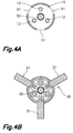
- said supporting inner core consists of three cylindrical bars arranged inside the holding support 10, or at least inscribed in the inner space of the hollow core of a sleeve, with a uniform angular separation between them, other configurations with a different number, position or geometry of the members forming said supporting inner core being possible.
- the holding support 10 is coupled to said supporting inner core 12 or to the body of said mobile handling unit 90 through adaptable support means 40 which provide at least a two-dimensional relative movement to at least one of the two ends of said holding support 10.
- said adaptable support means 40 consist of adaptable proximal means 41 located at the proximal end of the holding support 10, and of adaptable distal means 45 located at the distal end of the holding support 10.
- Said adaptable proximal means 41 and adaptable distal means 45 provide a relative three-dimensional movement between the holding support 10 and the supporting inner core 12, providing two-dimensional movement in a plane perpendicular to the holding support 10, by means of adaptable proximal radial means 42 and adaptable distal radial means 46. Relative movement in a third axial axis is also achieved as a result of adaptable proximal axial means 43 and adaptable distal axial means 47, thereby achieving an overall relative three-dimensional movement.
- said adaptable proximal radial means 42 of an elastic nature are arranged outside the holding support 10, allowing ample relative movement of said proximal end, and the adaptable distal radial means 46, also of an elastic nature, are arranged inside said holding support 10, which thus allows keeping the outer perimeter of the distal end of the holding support 10 interference-free.
- the adaptable support means 40 are formed by springs, but other devices could be used instead, such as, for example, gas pistons, hydraulic pistons, elastomers, magnets, or any other material or device that allows attaching two segments, enabling relative movement.
- first positioning means 44 configured so that the radial relative movement does not occur as long as the radial force applied on the holding support 10 does not exceed the force produced by the weight of a sleeve 60, said radial relative movement therefore only occurs when attempting to introduce the sleeve 60 in the holding support 10 and the latter is misaligned with respect to the geometric axis of said sleeve 60.
- said first positioning means 44 consist of a spherical body pressed against a concave body, said concave body being attached to the holding support 10, and said spherical body is arranged between said concave body and the adaptable proximal axial means 43, or vice versa, which are calibrated to keep said spherical body inside said concave body as long as the force applied on the holding support 10 does not exceed previously mentioned parameters. Therefore, since the spherical body is inside the concave body, the holding support 10 is in a rest position with respect to the supporting inner core 12.
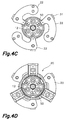
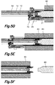
- a clamping carriage 20 equipped with gripping means 21 is connected to a motorized carriage 30, which allows movement between a gripping position (shown in Figures 5C and 5D ) in which said gripping means 21 interact with a sleeve 60 to hold it or release it, and a transport position (shown in Figures 5E and 5F ) in which said holding support 10 is partly or completely coupled with said sleeve 60.
- said clamping carriage 20 runs along the holding support 10 and the latter has a relative three-dimensional movement with respect to the supporting inner core 12 and to the mobile handling unit 90, said clamping carriage 20 also has that relative movement in order to remain aligned with the axis of the holding support 10 at all times.
- FIG. 3 and Figures 4A to 4E shows a motorized carriage 30 mechanically attached to at least one central screw spindle 50 coupled to the mobile handling unit 90 and arranged inside the holding support 10, such that the rotation of said screw spindle 50 causes the axial movement of said motorized carriage 30.
- the motorized carriage 30 is connected to the clamping carriage 20 through arms 31 through longitudinal openings 51 of said holding support 10, as can be seen in Figure 4B .
- said adaptable carriage means 49 in this example of an elastic nature
- said coupling plates 22 allows a relative movement between the motorized carriage 30 and the clamping carriage 20. Therefore by holding an annular grip 61 provided in the accessible head of the sleeve 60, the gripping means 21 can orient the entire clamping carriage 20 with respect to the geometric axis of the sleeve 60 and not with respect to the axis of the holding support 10 on which the clamping carriage 20 is assembled with the possibility of sliding.
- Said adaptable carriage means 49 can have second positioning means similar to those described above and located at the proximal end of the holding support 10. Said second positioning means can be calibrated with less tension, for example, than the first positioning means 44.
- the mobile handling unit 90 or the holding support 10 can have sensor means (not shown) intended for positioning and/or identifying the sleeves and/or their supports, which allows improving automatic self-positioning. It can also have position sensors that detect or allow inferring the relative position between the holding support 10 and the supporting inner core 12 in order to know the existing degree of misalignment, thereby allowing future corrections of the self-positioning.
- Said method includes a first step in which the mobile handling unit 90 aligns the holding support 10 with the sleeve-bearing shaft 80 or with a storage position ( Figure 5A ). In a second step it couples the distal end of the holding support 10 with the distal support of the sleeve-bearing shaft 80 ( Figure 5B ). In the third step shown in Figure 5C , the clamping carriage 20 is positioned in the previously mentioned gripping position to then in the fourth step close the gripping means 21, thereby gripping the sleeve 60 ( Figure 5D ).
- the motorized carriage 30 moves the clamping carriage 20, driving the sleeve 60 with it ( Figure 5E ) by the annular grip 61. It is during this step that said adaptable support means 40 can enter into action if the axis of the sleeve 60 and the axis of the holding support 10 are not perfectly aligned and coaxial.
- the holding support 10 is decoupled from the sleeve-bearing shaft 80 once the sleeve 60 is completely in the transport position coaxial to the mentioned holding support 10.
Landscapes
- Rotary Presses (AREA)
- Warehouses Or Storage Devices (AREA)
Priority Applications (4)
| Application Number | Priority Date | Filing Date | Title |
|---|---|---|---|
| ES13380046.6T ES2577253T3 (es) | 2013-10-07 | 2013-10-07 | Dispositivo automático de manipulación y transporte de camisas de impresión |
| EP13380046.6A EP2857200B1 (fr) | 2013-10-07 | 2013-10-07 | Dispositif de manipulation et de transport automatique pour manchons d'impression |
| US15/027,511 US9662924B2 (en) | 2013-10-07 | 2014-09-30 | Automatic handling and transport device for printing sleeves |
| PCT/IB2014/001954 WO2015052562A1 (fr) | 2013-10-07 | 2014-09-30 | Dispositif de manipulation et de transport automatique de manchons d'impression |
Applications Claiming Priority (1)
| Application Number | Priority Date | Filing Date | Title |
|---|---|---|---|
| EP13380046.6A EP2857200B1 (fr) | 2013-10-07 | 2013-10-07 | Dispositif de manipulation et de transport automatique pour manchons d'impression |
Publications (2)
| Publication Number | Publication Date |
|---|---|
| EP2857200A1 true EP2857200A1 (fr) | 2015-04-08 |
| EP2857200B1 EP2857200B1 (fr) | 2016-03-30 |
Family
ID=49518895
Family Applications (1)
| Application Number | Title | Priority Date | Filing Date |
|---|---|---|---|
| EP13380046.6A Active EP2857200B1 (fr) | 2013-10-07 | 2013-10-07 | Dispositif de manipulation et de transport automatique pour manchons d'impression |
Country Status (4)
| Country | Link |
|---|---|
| US (1) | US9662924B2 (fr) |
| EP (1) | EP2857200B1 (fr) |
| ES (1) | ES2577253T3 (fr) |
| WO (1) | WO2015052562A1 (fr) |
Cited By (3)
| Publication number | Priority date | Publication date | Assignee | Title |
|---|---|---|---|---|
| EP3199345A1 (fr) | 2016-01-29 | 2017-08-02 | Comexi Group Industries, S.A.U | Installation d'impression et procédé pour agencement de manchons dans ladite installation d'impression |
| IT202200016581A1 (it) * | 2022-08-04 | 2024-02-04 | Uteco Converting Spa | Apparecchiatura per la sostituzione automatica di maniche da stampa. |
| IT202200016587A1 (it) * | 2022-08-04 | 2024-02-04 | Uteco Converting Spa | Apparecchiatura per la sostituzione di maniche da stampa. |
Families Citing this family (3)
| Publication number | Priority date | Publication date | Assignee | Title |
|---|---|---|---|---|
| EP2857200B1 (fr) | 2013-10-07 | 2016-03-30 | Neopack, S.L. | Dispositif de manipulation et de transport automatique pour manchons d'impression |
| US12122145B2 (en) * | 2020-10-19 | 2024-10-22 | Bobst Bielefeld Gmbh | Method for automatically exchanging a sleeve of a printing tool |
| CN120002232B (zh) * | 2025-04-18 | 2025-12-26 | 武汉瑞晟精密机械有限公司 | 一种钢构件冲焊一体装置及其加工方法 |
Citations (4)
| Publication number | Priority date | Publication date | Assignee | Title |
|---|---|---|---|---|
| EP1093914A2 (fr) * | 1999-10-22 | 2001-04-25 | Heidelberger Druckmaschinen Aktiengesellschaft | Dispositif pour enlever un blanchet en caoutchouc en forme de manchon |
| EP1591248A1 (fr) * | 2004-04-30 | 2005-11-02 | MAN Roland Druckmaschinen AG | Dispositif pour fixer et enlever un manchon |
| EP1776231B1 (fr) | 2004-07-31 | 2008-03-12 | Windmöller & Hölscher KG | Systeme de changement de manchon |
| EP1705009B1 (fr) | 2004-01-14 | 2013-01-23 | Comexi Group Industries, S.A. | Dispositif automatique de manipulation et de transport de chemises d'impression |
Family Cites Families (2)
| Publication number | Priority date | Publication date | Assignee | Title |
|---|---|---|---|---|
| DE10050097A1 (de) * | 2000-10-09 | 2002-06-20 | Roland Man Druckmasch | Gummizylinderhülse für Offsetdruckmaschinen |
| EP2857200B1 (fr) | 2013-10-07 | 2016-03-30 | Neopack, S.L. | Dispositif de manipulation et de transport automatique pour manchons d'impression |
-
2013
- 2013-10-07 EP EP13380046.6A patent/EP2857200B1/fr active Active
- 2013-10-07 ES ES13380046.6T patent/ES2577253T3/es active Active
-
2014
- 2014-09-30 WO PCT/IB2014/001954 patent/WO2015052562A1/fr not_active Ceased
- 2014-09-30 US US15/027,511 patent/US9662924B2/en active Active
Patent Citations (4)
| Publication number | Priority date | Publication date | Assignee | Title |
|---|---|---|---|---|
| EP1093914A2 (fr) * | 1999-10-22 | 2001-04-25 | Heidelberger Druckmaschinen Aktiengesellschaft | Dispositif pour enlever un blanchet en caoutchouc en forme de manchon |
| EP1705009B1 (fr) | 2004-01-14 | 2013-01-23 | Comexi Group Industries, S.A. | Dispositif automatique de manipulation et de transport de chemises d'impression |
| EP1591248A1 (fr) * | 2004-04-30 | 2005-11-02 | MAN Roland Druckmaschinen AG | Dispositif pour fixer et enlever un manchon |
| EP1776231B1 (fr) | 2004-07-31 | 2008-03-12 | Windmöller & Hölscher KG | Systeme de changement de manchon |
Cited By (6)
| Publication number | Priority date | Publication date | Assignee | Title |
|---|---|---|---|---|
| EP3199345A1 (fr) | 2016-01-29 | 2017-08-02 | Comexi Group Industries, S.A.U | Installation d'impression et procédé pour agencement de manchons dans ladite installation d'impression |
| IT202200016581A1 (it) * | 2022-08-04 | 2024-02-04 | Uteco Converting Spa | Apparecchiatura per la sostituzione automatica di maniche da stampa. |
| IT202200016587A1 (it) * | 2022-08-04 | 2024-02-04 | Uteco Converting Spa | Apparecchiatura per la sostituzione di maniche da stampa. |
| EP4316846A1 (fr) * | 2022-08-04 | 2024-02-07 | Uteco Converting S.p.A. | Appareil et procédé pour remplacer automatiquement des manchons d'impression |
| EP4316847A1 (fr) * | 2022-08-04 | 2024-02-07 | Uteco Converting S.p.A. | Dispositif pour remplacer des manchons d'impression |
| US12544916B2 (en) | 2022-08-04 | 2026-02-10 | Uteco Converting S.P.A. | Apparatus for automatically replacing printing sleeves |
Also Published As
| Publication number | Publication date |
|---|---|
| WO2015052562A1 (fr) | 2015-04-16 |
| US9662924B2 (en) | 2017-05-30 |
| ES2577253T3 (es) | 2016-07-13 |
| EP2857200B1 (fr) | 2016-03-30 |
| US20160243872A1 (en) | 2016-08-25 |
Similar Documents
| Publication | Publication Date | Title |
|---|---|---|
| US9662924B2 (en) | Automatic handling and transport device for printing sleeves | |
| EP3070480B1 (fr) | Appareil, unité et procédé de fermeture de bouchon | |
| US7458244B2 (en) | Feeding unit and method for feeding an element to a treatment unit | |
| KR102060867B1 (ko) | O링 부착 장치 및 방법 | |
| CN102076927A (zh) | 管状件操纵设备和方法 | |
| JP7445603B2 (ja) | 蓋取付け/取外しシステム及び方法 | |
| EP3199345B1 (fr) | Installation d'impression et procédé pour agencement de manchons dans ladite installation d'impression | |
| WO2015016757A1 (fr) | Dispositif permettant de manipuler des composants de rame de forage par rapport à un appareil de forage de roche et appareil de forage de roche | |
| EP2990150B1 (fr) | Obturateur anti-vibrations pour l'usinage de tubes et procédé de placement dudit obturateur à l'intérieur d'un tube | |
| JP5696745B2 (ja) | 伝熱管拡管装置及び伝熱管拡管方法 | |
| US20150337685A1 (en) | Method and device for mounting and removing a turbine component | |
| US8474130B2 (en) | Tripod constant velocity joint, and method and device for assembling same | |
| CN102795538A (zh) | 一种新型长杆吊具 | |
| US20200063508A1 (en) | Pipe handling unit | |
| EP2657160B1 (fr) | Cartouche à distribution pneumatique et appareil de déchargement de celle-ci | |
| EP1870988A1 (fr) | Procédé et dispositif d'équilibrage d'un rotor d'une machine électrique | |
| EP4252978B1 (fr) | Manipulateur articulé pour se déplacer dans un échangeur de chaleur et l'entretenir | |
| KR100552419B1 (ko) | 토치회전형 용접기 | |
| US11851824B2 (en) | Spike puller and method for pulling a railroad spike of a track | |
| US20200240559A1 (en) | Connection device for joining two pipe sections | |
| CN110768491A (zh) | 电导体的排列装置 | |
| US8920221B2 (en) | Stuffing tube centering device and method for centering a stuffing tube | |
| KR200335481Y1 (ko) | 토치회전형 용접기 | |
| US10450812B2 (en) | Rod handler improvements | |
| US20150354634A1 (en) | Coupling device for a drive device, and drive device |
Legal Events
| Date | Code | Title | Description |
|---|---|---|---|
| PUAI | Public reference made under article 153(3) epc to a published international application that has entered the european phase |
Free format text: ORIGINAL CODE: 0009012 |
|
| 17P | Request for examination filed |
Effective date: 20131007 |
|
| AK | Designated contracting states |
Kind code of ref document: A1 Designated state(s): AL AT BE BG CH CY CZ DE DK EE ES FI FR GB GR HR HU IE IS IT LI LT LU LV MC MK MT NL NO PL PT RO RS SE SI SK SM TR |
|
| AX | Request for extension of the european patent |
Extension state: BA ME |
|
| RIN1 | Information on inventor provided before grant (corrected) |
Inventor name: RUIZ SUESA, LUIS ANTONIO Inventor name: SCHOONMAN, ADELBERT LUCAS Inventor name: GARRIDO FERNANDEZ, TONI Inventor name: PUIG VILA, JORDI |
|
| GRAP | Despatch of communication of intention to grant a patent |
Free format text: ORIGINAL CODE: EPIDOSNIGR1 |
|
| R17P | Request for examination filed (corrected) |
Effective date: 20150819 |
|
| RBV | Designated contracting states (corrected) |
Designated state(s): AL AT BE BG CH CY CZ DE DK EE ES FI FR GB GR HR HU IE IS IT LI LT LU LV MC MK MT NL NO PL PT RO RS SE SI SK SM TR |
|
| INTG | Intention to grant announced |
Effective date: 20151001 |
|
| RIN1 | Information on inventor provided before grant (corrected) |
Inventor name: RUIZ SUESA, LUIS ANTONIO Inventor name: PUIG VILA, JORDI Inventor name: GARRIDO FERNANDEZ, TONI Inventor name: SCHOONMAN, ADELBERT LUCAS |
|
| GRAS | Grant fee paid |
Free format text: ORIGINAL CODE: EPIDOSNIGR3 |
|
| GRAA | (expected) grant |
Free format text: ORIGINAL CODE: 0009210 |
|
| AK | Designated contracting states |
Kind code of ref document: B1 Designated state(s): AL AT BE BG CH CY CZ DE DK EE ES FI FR GB GR HR HU IE IS IT LI LT LU LV MC MK MT NL NO PL PT RO RS SE SI SK SM TR |
|
| REG | Reference to a national code |
Ref country code: GB Ref legal event code: FG4D |
|
| REG | Reference to a national code |
Ref country code: CH Ref legal event code: EP |
|
| REG | Reference to a national code |
Ref country code: AT Ref legal event code: REF Ref document number: 784909 Country of ref document: AT Kind code of ref document: T Effective date: 20160415 |
|
| REG | Reference to a national code |
Ref country code: IE Ref legal event code: FG4D |
|
| REG | Reference to a national code |
Ref country code: DE Ref legal event code: R096 Ref document number: 602013005913 Country of ref document: DE |
|
| REG | Reference to a national code |
Ref country code: NL Ref legal event code: FP |
|
| REG | Reference to a national code |
Ref country code: ES Ref legal event code: FG2A Ref document number: 2577253 Country of ref document: ES Kind code of ref document: T3 Effective date: 20160713 |
|
| REG | Reference to a national code |
Ref country code: LT Ref legal event code: MG4D |
|
| PG25 | Lapsed in a contracting state [announced via postgrant information from national office to epo] |
Ref country code: HR Free format text: LAPSE BECAUSE OF FAILURE TO SUBMIT A TRANSLATION OF THE DESCRIPTION OR TO PAY THE FEE WITHIN THE PRESCRIBED TIME-LIMIT Effective date: 20160330 Ref country code: GR Free format text: LAPSE BECAUSE OF FAILURE TO SUBMIT A TRANSLATION OF THE DESCRIPTION OR TO PAY THE FEE WITHIN THE PRESCRIBED TIME-LIMIT Effective date: 20160701 Ref country code: NO Free format text: LAPSE BECAUSE OF FAILURE TO SUBMIT A TRANSLATION OF THE DESCRIPTION OR TO PAY THE FEE WITHIN THE PRESCRIBED TIME-LIMIT Effective date: 20160630 Ref country code: FI Free format text: LAPSE BECAUSE OF FAILURE TO SUBMIT A TRANSLATION OF THE DESCRIPTION OR TO PAY THE FEE WITHIN THE PRESCRIBED TIME-LIMIT Effective date: 20160330 |
|
| REG | Reference to a national code |
Ref country code: AT Ref legal event code: MK05 Ref document number: 784909 Country of ref document: AT Kind code of ref document: T Effective date: 20160330 |
|
| PG25 | Lapsed in a contracting state [announced via postgrant information from national office to epo] |
Ref country code: LT Free format text: LAPSE BECAUSE OF FAILURE TO SUBMIT A TRANSLATION OF THE DESCRIPTION OR TO PAY THE FEE WITHIN THE PRESCRIBED TIME-LIMIT Effective date: 20160330 Ref country code: SE Free format text: LAPSE BECAUSE OF FAILURE TO SUBMIT A TRANSLATION OF THE DESCRIPTION OR TO PAY THE FEE WITHIN THE PRESCRIBED TIME-LIMIT Effective date: 20160330 Ref country code: LV Free format text: LAPSE BECAUSE OF FAILURE TO SUBMIT A TRANSLATION OF THE DESCRIPTION OR TO PAY THE FEE WITHIN THE PRESCRIBED TIME-LIMIT Effective date: 20160330 Ref country code: RS Free format text: LAPSE BECAUSE OF FAILURE TO SUBMIT A TRANSLATION OF THE DESCRIPTION OR TO PAY THE FEE WITHIN THE PRESCRIBED TIME-LIMIT Effective date: 20160330 |
|
| PG25 | Lapsed in a contracting state [announced via postgrant information from national office to epo] |
Ref country code: EE Free format text: LAPSE BECAUSE OF FAILURE TO SUBMIT A TRANSLATION OF THE DESCRIPTION OR TO PAY THE FEE WITHIN THE PRESCRIBED TIME-LIMIT Effective date: 20160330 Ref country code: IS Free format text: LAPSE BECAUSE OF FAILURE TO SUBMIT A TRANSLATION OF THE DESCRIPTION OR TO PAY THE FEE WITHIN THE PRESCRIBED TIME-LIMIT Effective date: 20160730 Ref country code: PL Free format text: LAPSE BECAUSE OF FAILURE TO SUBMIT A TRANSLATION OF THE DESCRIPTION OR TO PAY THE FEE WITHIN THE PRESCRIBED TIME-LIMIT Effective date: 20160330 |
|
| PG25 | Lapsed in a contracting state [announced via postgrant information from national office to epo] |
Ref country code: PT Free format text: LAPSE BECAUSE OF FAILURE TO SUBMIT A TRANSLATION OF THE DESCRIPTION OR TO PAY THE FEE WITHIN THE PRESCRIBED TIME-LIMIT Effective date: 20160801 Ref country code: SK Free format text: LAPSE BECAUSE OF FAILURE TO SUBMIT A TRANSLATION OF THE DESCRIPTION OR TO PAY THE FEE WITHIN THE PRESCRIBED TIME-LIMIT Effective date: 20160330 Ref country code: SM Free format text: LAPSE BECAUSE OF FAILURE TO SUBMIT A TRANSLATION OF THE DESCRIPTION OR TO PAY THE FEE WITHIN THE PRESCRIBED TIME-LIMIT Effective date: 20160330 Ref country code: AT Free format text: LAPSE BECAUSE OF FAILURE TO SUBMIT A TRANSLATION OF THE DESCRIPTION OR TO PAY THE FEE WITHIN THE PRESCRIBED TIME-LIMIT Effective date: 20160330 Ref country code: RO Free format text: LAPSE BECAUSE OF FAILURE TO SUBMIT A TRANSLATION OF THE DESCRIPTION OR TO PAY THE FEE WITHIN THE PRESCRIBED TIME-LIMIT Effective date: 20160330 Ref country code: CZ Free format text: LAPSE BECAUSE OF FAILURE TO SUBMIT A TRANSLATION OF THE DESCRIPTION OR TO PAY THE FEE WITHIN THE PRESCRIBED TIME-LIMIT Effective date: 20160330 |
|
| PG25 | Lapsed in a contracting state [announced via postgrant information from national office to epo] |
Ref country code: BE Free format text: LAPSE BECAUSE OF FAILURE TO SUBMIT A TRANSLATION OF THE DESCRIPTION OR TO PAY THE FEE WITHIN THE PRESCRIBED TIME-LIMIT Effective date: 20160330 |
|
| REG | Reference to a national code |
Ref country code: DE Ref legal event code: R097 Ref document number: 602013005913 Country of ref document: DE |
|
| PG25 | Lapsed in a contracting state [announced via postgrant information from national office to epo] |
Ref country code: DK Free format text: LAPSE BECAUSE OF FAILURE TO SUBMIT A TRANSLATION OF THE DESCRIPTION OR TO PAY THE FEE WITHIN THE PRESCRIBED TIME-LIMIT Effective date: 20160330 |
|
| PLBE | No opposition filed within time limit |
Free format text: ORIGINAL CODE: 0009261 |
|
| STAA | Information on the status of an ep patent application or granted ep patent |
Free format text: STATUS: NO OPPOSITION FILED WITHIN TIME LIMIT |
|
| 26N | No opposition filed |
Effective date: 20170103 |
|
| PG25 | Lapsed in a contracting state [announced via postgrant information from national office to epo] |
Ref country code: SI Free format text: LAPSE BECAUSE OF FAILURE TO SUBMIT A TRANSLATION OF THE DESCRIPTION OR TO PAY THE FEE WITHIN THE PRESCRIBED TIME-LIMIT Effective date: 20160330 |
|
| REG | Reference to a national code |
Ref country code: CH Ref legal event code: PL |
|
| REG | Reference to a national code |
Ref country code: IE Ref legal event code: MM4A |
|
| REG | Reference to a national code |
Ref country code: FR Ref legal event code: ST Effective date: 20170630 |
|
| PG25 | Lapsed in a contracting state [announced via postgrant information from national office to epo] |
Ref country code: LI Free format text: LAPSE BECAUSE OF NON-PAYMENT OF DUE FEES Effective date: 20161031 Ref country code: FR Free format text: LAPSE BECAUSE OF NON-PAYMENT OF DUE FEES Effective date: 20161102 Ref country code: CH Free format text: LAPSE BECAUSE OF NON-PAYMENT OF DUE FEES Effective date: 20161031 |
|
| PG25 | Lapsed in a contracting state [announced via postgrant information from national office to epo] |
Ref country code: LU Free format text: LAPSE BECAUSE OF NON-PAYMENT OF DUE FEES Effective date: 20161007 |
|
| PG25 | Lapsed in a contracting state [announced via postgrant information from national office to epo] |
Ref country code: IE Free format text: LAPSE BECAUSE OF NON-PAYMENT OF DUE FEES Effective date: 20161007 |
|
| REG | Reference to a national code |
Ref country code: ES Ref legal event code: PC2A Owner name: COMEXI GROUP INDUSTRIES, SAU Effective date: 20180227 |
|
| PG25 | Lapsed in a contracting state [announced via postgrant information from national office to epo] |
Ref country code: HU Free format text: LAPSE BECAUSE OF FAILURE TO SUBMIT A TRANSLATION OF THE DESCRIPTION OR TO PAY THE FEE WITHIN THE PRESCRIBED TIME-LIMIT; INVALID AB INITIO Effective date: 20131007 |
|
| GBPC | Gb: european patent ceased through non-payment of renewal fee |
Effective date: 20171007 |
|
| PG25 | Lapsed in a contracting state [announced via postgrant information from national office to epo] |
Ref country code: MC Free format text: LAPSE BECAUSE OF FAILURE TO SUBMIT A TRANSLATION OF THE DESCRIPTION OR TO PAY THE FEE WITHIN THE PRESCRIBED TIME-LIMIT Effective date: 20160330 Ref country code: CY Free format text: LAPSE BECAUSE OF FAILURE TO SUBMIT A TRANSLATION OF THE DESCRIPTION OR TO PAY THE FEE WITHIN THE PRESCRIBED TIME-LIMIT Effective date: 20160330 Ref country code: MT Free format text: LAPSE BECAUSE OF NON-PAYMENT OF DUE FEES Effective date: 20161031 Ref country code: MK Free format text: LAPSE BECAUSE OF FAILURE TO SUBMIT A TRANSLATION OF THE DESCRIPTION OR TO PAY THE FEE WITHIN THE PRESCRIBED TIME-LIMIT Effective date: 20160330 |
|
| PG25 | Lapsed in a contracting state [announced via postgrant information from national office to epo] |
Ref country code: GB Free format text: LAPSE BECAUSE OF NON-PAYMENT OF DUE FEES Effective date: 20171007 Ref country code: BG Free format text: LAPSE BECAUSE OF FAILURE TO SUBMIT A TRANSLATION OF THE DESCRIPTION OR TO PAY THE FEE WITHIN THE PRESCRIBED TIME-LIMIT Effective date: 20160330 |
|
| PG25 | Lapsed in a contracting state [announced via postgrant information from national office to epo] |
Ref country code: TR Free format text: LAPSE BECAUSE OF FAILURE TO SUBMIT A TRANSLATION OF THE DESCRIPTION OR TO PAY THE FEE WITHIN THE PRESCRIBED TIME-LIMIT Effective date: 20160330 Ref country code: AL Free format text: LAPSE BECAUSE OF FAILURE TO SUBMIT A TRANSLATION OF THE DESCRIPTION OR TO PAY THE FEE WITHIN THE PRESCRIBED TIME-LIMIT Effective date: 20160330 |
|
| REG | Reference to a national code |
Ref country code: DE Ref legal event code: R081 Ref document number: 602013005913 Country of ref document: DE Owner name: COMEXI GROUP INDUSTRIES, SAU, RIUDELLOTS DE LA, ES Free format text: FORMER OWNER: NEOPACK, S.L., RIUDELLOTS DE LA SELVA, GIRONA, ES |
|
| P01 | Opt-out of the competence of the unified patent court (upc) registered |
Effective date: 20230504 |
|
| PGFP | Annual fee paid to national office [announced via postgrant information from national office to epo] |
Ref country code: NL Payment date: 20251030 Year of fee payment: 13 |
|
| PGFP | Annual fee paid to national office [announced via postgrant information from national office to epo] |
Ref country code: DE Payment date: 20251126 Year of fee payment: 13 |
|
| PGFP | Annual fee paid to national office [announced via postgrant information from national office to epo] |
Ref country code: IT Payment date: 20251029 Year of fee payment: 13 |
|
| PGFP | Annual fee paid to national office [announced via postgrant information from national office to epo] |
Ref country code: ES Payment date: 20251125 Year of fee payment: 13 |