EP2857202B1 - Unité d'entraînement de tête et imprimante à jet d'encre - Google Patents
Unité d'entraînement de tête et imprimante à jet d'encre Download PDFInfo
- Publication number
- EP2857202B1 EP2857202B1 EP13794021.9A EP13794021A EP2857202B1 EP 2857202 B1 EP2857202 B1 EP 2857202B1 EP 13794021 A EP13794021 A EP 13794021A EP 2857202 B1 EP2857202 B1 EP 2857202B1
- Authority
- EP
- European Patent Office
- Prior art keywords
- signal
- unit
- drive
- head
- meniscus
- Prior art date
- Legal status (The legal status is an assumption and is not a legal conclusion. Google has not performed a legal analysis and makes no representation as to the accuracy of the status listed.)
- Active
Links
Images




Classifications
-
- B—PERFORMING OPERATIONS; TRANSPORTING
- B41—PRINTING; LINING MACHINES; TYPEWRITERS; STAMPS
- B41J—TYPEWRITERS; SELECTIVE PRINTING MECHANISMS, i.e. MECHANISMS PRINTING OTHERWISE THAN FROM A FORME; CORRECTION OF TYPOGRAPHICAL ERRORS
- B41J2/00—Typewriters or selective printing mechanisms characterised by the printing or marking process for which they are designed
- B41J2/005—Typewriters or selective printing mechanisms characterised by the printing or marking process for which they are designed characterised by bringing liquid or particles selectively into contact with a printing material
- B41J2/01—Ink jet
- B41J2/015—Ink jet characterised by the jet generation process
- B41J2/04—Ink jet characterised by the jet generation process generating single droplets or particles on demand
- B41J2/045—Ink jet characterised by the jet generation process generating single droplets or particles on demand by pressure, e.g. electromechanical transducers
- B41J2/04501—Control methods or devices therefor, e.g. driver circuits, control circuits
- B41J2/04573—Timing; Delays
-
- B—PERFORMING OPERATIONS; TRANSPORTING
- B41—PRINTING; LINING MACHINES; TYPEWRITERS; STAMPS
- B41J—TYPEWRITERS; SELECTIVE PRINTING MECHANISMS, i.e. MECHANISMS PRINTING OTHERWISE THAN FROM A FORME; CORRECTION OF TYPOGRAPHICAL ERRORS
- B41J2/00—Typewriters or selective printing mechanisms characterised by the printing or marking process for which they are designed
- B41J2/005—Typewriters or selective printing mechanisms characterised by the printing or marking process for which they are designed characterised by bringing liquid or particles selectively into contact with a printing material
- B41J2/01—Ink jet
-
- B—PERFORMING OPERATIONS; TRANSPORTING
- B41—PRINTING; LINING MACHINES; TYPEWRITERS; STAMPS
- B41J—TYPEWRITERS; SELECTIVE PRINTING MECHANISMS, i.e. MECHANISMS PRINTING OTHERWISE THAN FROM A FORME; CORRECTION OF TYPOGRAPHICAL ERRORS
- B41J2/00—Typewriters or selective printing mechanisms characterised by the printing or marking process for which they are designed
- B41J2/005—Typewriters or selective printing mechanisms characterised by the printing or marking process for which they are designed characterised by bringing liquid or particles selectively into contact with a printing material
- B41J2/01—Ink jet
- B41J2/015—Ink jet characterised by the jet generation process
- B41J2/04—Ink jet characterised by the jet generation process generating single droplets or particles on demand
- B41J2/045—Ink jet characterised by the jet generation process generating single droplets or particles on demand by pressure, e.g. electromechanical transducers
- B41J2/04501—Control methods or devices therefor, e.g. driver circuits, control circuits
- B41J2/0458—Control methods or devices therefor, e.g. driver circuits, control circuits controlling heads based on heating elements forming bubbles
-
- B—PERFORMING OPERATIONS; TRANSPORTING
- B41—PRINTING; LINING MACHINES; TYPEWRITERS; STAMPS
- B41J—TYPEWRITERS; SELECTIVE PRINTING MECHANISMS, i.e. MECHANISMS PRINTING OTHERWISE THAN FROM A FORME; CORRECTION OF TYPOGRAPHICAL ERRORS
- B41J2/00—Typewriters or selective printing mechanisms characterised by the printing or marking process for which they are designed
- B41J2/005—Typewriters or selective printing mechanisms characterised by the printing or marking process for which they are designed characterised by bringing liquid or particles selectively into contact with a printing material
- B41J2/01—Ink jet
- B41J2/015—Ink jet characterised by the jet generation process
- B41J2/04—Ink jet characterised by the jet generation process generating single droplets or particles on demand
- B41J2/045—Ink jet characterised by the jet generation process generating single droplets or particles on demand by pressure, e.g. electromechanical transducers
- B41J2/04501—Control methods or devices therefor, e.g. driver circuits, control circuits
- B41J2/04581—Control methods or devices therefor, e.g. driver circuits, control circuits controlling heads based on piezoelectric elements
-
- B—PERFORMING OPERATIONS; TRANSPORTING
- B41—PRINTING; LINING MACHINES; TYPEWRITERS; STAMPS
- B41J—TYPEWRITERS; SELECTIVE PRINTING MECHANISMS, i.e. MECHANISMS PRINTING OTHERWISE THAN FROM A FORME; CORRECTION OF TYPOGRAPHICAL ERRORS
- B41J2/00—Typewriters or selective printing mechanisms characterised by the printing or marking process for which they are designed
- B41J2/005—Typewriters or selective printing mechanisms characterised by the printing or marking process for which they are designed characterised by bringing liquid or particles selectively into contact with a printing material
- B41J2/01—Ink jet
- B41J2/015—Ink jet characterised by the jet generation process
- B41J2/04—Ink jet characterised by the jet generation process generating single droplets or particles on demand
- B41J2/045—Ink jet characterised by the jet generation process generating single droplets or particles on demand by pressure, e.g. electromechanical transducers
- B41J2/04501—Control methods or devices therefor, e.g. driver circuits, control circuits
- B41J2/04588—Control methods or devices therefor, e.g. driver circuits, control circuits using a specific waveform
-
- B—PERFORMING OPERATIONS; TRANSPORTING
- B41—PRINTING; LINING MACHINES; TYPEWRITERS; STAMPS
- B41J—TYPEWRITERS; SELECTIVE PRINTING MECHANISMS, i.e. MECHANISMS PRINTING OTHERWISE THAN FROM A FORME; CORRECTION OF TYPOGRAPHICAL ERRORS
- B41J2/00—Typewriters or selective printing mechanisms characterised by the printing or marking process for which they are designed
- B41J2/005—Typewriters or selective printing mechanisms characterised by the printing or marking process for which they are designed characterised by bringing liquid or particles selectively into contact with a printing material
- B41J2/01—Ink jet
- B41J2/015—Ink jet characterised by the jet generation process
- B41J2/04—Ink jet characterised by the jet generation process generating single droplets or particles on demand
- B41J2/045—Ink jet characterised by the jet generation process generating single droplets or particles on demand by pressure, e.g. electromechanical transducers
- B41J2/04501—Control methods or devices therefor, e.g. driver circuits, control circuits
- B41J2/04596—Non-ejecting pulses
-
- B—PERFORMING OPERATIONS; TRANSPORTING
- B41—PRINTING; LINING MACHINES; TYPEWRITERS; STAMPS
- B41J—TYPEWRITERS; SELECTIVE PRINTING MECHANISMS, i.e. MECHANISMS PRINTING OTHERWISE THAN FROM A FORME; CORRECTION OF TYPOGRAPHICAL ERRORS
- B41J2/00—Typewriters or selective printing mechanisms characterised by the printing or marking process for which they are designed
- B41J2/005—Typewriters or selective printing mechanisms characterised by the printing or marking process for which they are designed characterised by bringing liquid or particles selectively into contact with a printing material
- B41J2/01—Ink jet
- B41J2/135—Nozzles
- B41J2/165—Prevention or detection of nozzle clogging, e.g. cleaning, capping or moistening for nozzles
- B41J2/16517—Cleaning of print head nozzles
- B41J2/1652—Cleaning of print head nozzles by driving a fluid through the nozzles to the outside thereof, e.g. by applying pressure to the inside or vacuum at the outside of the print head
- B41J2/16526—Cleaning of print head nozzles by driving a fluid through the nozzles to the outside thereof, e.g. by applying pressure to the inside or vacuum at the outside of the print head by applying pressure only
-
- B—PERFORMING OPERATIONS; TRANSPORTING
- B41—PRINTING; LINING MACHINES; TYPEWRITERS; STAMPS
- B41J—TYPEWRITERS; SELECTIVE PRINTING MECHANISMS, i.e. MECHANISMS PRINTING OTHERWISE THAN FROM A FORME; CORRECTION OF TYPOGRAPHICAL ERRORS
- B41J2/00—Typewriters or selective printing mechanisms characterised by the printing or marking process for which they are designed
- B41J2/005—Typewriters or selective printing mechanisms characterised by the printing or marking process for which they are designed characterised by bringing liquid or particles selectively into contact with a printing material
- B41J2/01—Ink jet
- B41J2/17—Ink jet characterised by ink handling
- B41J2/175—Ink supply systems ; Circuit parts therefor
Definitions
- Some of inkjet printers include a head drive unit equipped with an inkjet head driven based on a drive signal and a head drive apparatus that applies a discharge signal to the inkjet head based on image data and a print timing signal input from the outside and discharges droplets from nozzles to form an image on a recording medium as well as a print control apparatus that outputs the image data and the print timing signal to the head drive unit.
- a printer control apparatus a PC or the like
- the print trigger signal is input from a carriage apparatus when the inkjet head reaches an image forming region for the recording medium based on positional information of the inkjet head in a recording medium width direction (a main scanning direction).
- the print control apparatus generates the print timing signal in the image forming region based on this print trigger signal and continuously outputs this signal.
- the printer control apparatus does not have means for acquiring a print trigger signal output from the carriage apparatus that is another apparatus and timing to start subsequent print is unknown, it is difficult to determine a level of dummy image data to be provided. Moreover, since excess data that is the dummy image data is transmitted to the print control apparatus, there occurs a problem that an actual transfer rate is lowered and a print throughput is also decreased.
- the print control apparatus when the print control apparatus is set to transmit the dummy image data to the head drive apparatus, it may be possible to realize application of the meniscus oscillation signal even if the inkjet head is present outside the image forming region.
- the print control apparatus does not have an image data generating function, unnecessary processing for generating the dummy image data is added. Since the print control apparatus requires ultrahigh-speed processing, e.g., data reception from an external apparatus (the printer control apparatus) or storage of image data in a memory in the apparatus, if unnecessary processing is added, a faster CPU or FPGA is required to meet demanded specifications, which results in a great increase in cost.
- it is an object of the present invention is to provide a head drive unit that enables applying a meniscus oscillation signal and preventing an increase in viscosity of an ink in a nozzle even when an inkjet head is present outside an image forming region of a recording medium where a print timing signal is not acquired, and to provide an inkjet printer including this head drive unit.
- the discharge failure problem caused due to an increase in viscosity of the ink can be avoided by forcedly continuously discharging droplets from the nozzles.
- a signal used for forcedly discharging the droplets (which will be referred to as a flushing signal hereinafter) cannot be applied to the inkjet head, and there is the same problem as that in case of the meniscus oscillation signal.
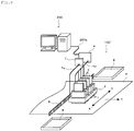
- FIG. 1 is an overall structural view showing an example of an inkjet system including an inkjet printer
- FIG. 2 is a structural block diagram thereof.
- reference numeral 100 denotes an inkjet printer
- 200 designates a printer control apparatus that is an external apparatus configured to control the entire inkjet printer 100.
- a configuration of the head 1 is not really matter, it is arbitrary to adopt, e.g., a configuration that a piezoelectric element such as a PZT is driven by applying a drive signal, a volume of an ink chamber is contracted, and a pressure is provided to the ink to thereby discharge the ink from each nozzle or a configuration that a heater is energized by applying a drive signal, the ink is heated to generate air bubbles, and the ink in the ink chamber is discharged from the nozzles by a rupture action of the air bubbles.
- a piezoelectric element such as a PZT
- a recording medium P is arranged below the carriage 2 to face the nozzle surfaces of the heads 1.
- the recording medium P is intermittently carried at a predetermined velocity along a sub-scanning direction represented as Y in the drawing by a non-illustrated recording medium carrying apparatus having, e.g., a carrying roller pair that holds the recording medium P and rotates to perform carriage and a carrying belt that has the recording medium P mounted thereon and carries it.
- each head drive apparatus 3 When image data, a print timing signal, or various kinds of control commands are transmitted from a print control apparatus 4 formed of, e.g., a CPU or an FPGA provided in the inkjet printer 100 through a signal line 4a, each head drive apparatus 3 outputs a drive signal to each head 1 based on the image data, the print timing signal, and the various kinds of control commands. Particulars of an internal structure of the head drive apparatus 3 will be described later.
- reference numeral 5 denotes a linear encoder, and it is arranged along the main scanning direction.
- An encoder sensor 6 (see FIG. 2 ) is provided to the carriage 2, and continuous pulse signals are detected from the linear encoder 5 when the carriage 2 moves along the main scanning direction.
- the combination of the linear encoder 5 and the encoder sensor 6 is an example of positional information detecting apparatus for detecting positional information of each head 1 relative to the recording medium P.
- Each detected pulse signal is transmitted to a mechanical control apparatus 7 formed of, e.g., the CPU or the FPGA provided in the inkjet printer 100 through a signal line 7a.
- the mechanical control apparatus 7 acquires positional information of the carriage 2 along the main scanning direction based on the pulse signal.
- the mechanical control apparatus 7 controls reciprocation of the carriage 2 along the main scanning direction and carriage of the recording medium P along the sub-scanning direction.
- Each head 1 is driven and controlled by the head drive apparatus 3 based on image data, a print timing signal, or various kinds of control commands transmitted from the print control apparatus 4 during a period that the heads 1 are present in an image forming region on the recording medium P in a process of the reciprocation of the carriage 2 along the main scanning direction controlled by this mechanical control apparatus 7, and each head 1 discharges droplets from the nozzles to form an image on the recording medium P.
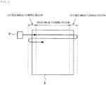
- the carriage 2 starts acceleration from the outside of the image forming region on one side of the recording medium P, cuts across the image forming region on the recording medium P at a fixed velocity, again reaches the outside of the image forming region on the other side of the recording medium P, and then repeats an operation of performing deceleration, stop, and reversal outside the image forming region and again starting acceleration toward the inside of the image forming region.
- the mechanical control apparatus 7 is configured to determine whether the carriage 2 has reached the image forming region from the outside of the image forming region for the recording medium P from acquired positional information of the carriage 2 along the main scanning direction.
- the mechanical control apparatus 7 when the carriage 2 comes close to the image forming region, the mechanical control apparatus 7 generates a print trigger signal indicative of start of print and transmits it to the print control apparatus 4.
- the print control apparatus 4 generates the print timing signal upon reception of the print trigger signal only when the carriage 2 is present in the image forming region, and it transmits this signal to each head drive apparatus 3 together with image data and any other various kinds of control commands.
- the printer control apparatus 200 that is an external apparatus of the inkjet printer 100 is constituted of a PC.
- the printer control apparatus 200 holds image data and transmits the image data and various kinds of control commands that control the entire inkjet printer 100 to the print control apparatus 4.
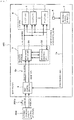
- FIG. 4 is a structural block diagram showing an example of the internal configuration of the head drive apparatus 3.
- the head drive apparatus 3 has a drive signal output unit 31 and a drive signal selection unit 32. As represented by examples in FIG. 5 , this head drive apparatus 3 can generate a discharge signal ( FIG. 5(a) ) used for discharge a droplet from a nozzle to form an image and a meniscus oscillation signal ( FIG. 5 (b) ) that has a lower peak value than the discharge signal and is used for oscillating a meniscus at each nozzle tip without discharging a droplet from the nozzle as a drive signal output to the head 1.
- the drive signal selection unit 32 has a discharge signal waveform data memory 321a that stores waveform data of the discharge signal and a meniscus oscillation signal waveform data memory 321b that stores waveform data of the meniscus oscillation signal.
- the discharge signal waveform data in the discharge signal waveform data memory 321a and the meniscus oscillation signal waveform data in the meniscus oscillation signal waveform data memory 321b are output to the drive signal output unit 31.
- the drive signal output unit 31 has a control unit 311 that outputs a head control signal to each head 1, a drive signal generation unit 312 that is controlled by the control unit 311 and outputs a drive signal to the head 1, and a waveform switch unit 313 that is controlled by the control unit 311 and switches a drive signal waveform that is output to the drive signal generation unit 312 to either a discharge signal waveform from the discharge signal waveform data memory 321a of the drive signal selection unit 32 or a meniscus oscillation signal waveform from the meniscus oscillation signal waveform data memory 321b.
- the control unit 311 controls the waveform switch unit 313 based on a discharge signal request signal or a meniscus oscillation signal request signal output from the drive signal selection unit 32 and switches a drive signal applied to the head 1 to either the discharge signal or the meniscus oscillation signal.
- Image data and the print timing signal are input to this control unit 311 from the print control apparatus 4.
- the control unit 311 outputs the discharge signal to each head 1 from the drive signal generation unit 312 based on the image data and the print timing signal. As a result, droplets are discharged from the nozzles, and image formation is carried out.
- each of the discharge signal shown in FIG. 5(a) and the meniscus oscillation signal shown in FIG. 5(b) is an example and can be appropriately set in accordance with the configuration of the head 1.
- the drive signal selection unit 32 has the following configuration.
- the print timing signal that is continuously output from the print control apparatus 4 is also input to the drive signal selection unit 32.
- An interrupted time measurement unit 324 that monitors cyclic input of the continuous print timing signal is provided to the drive signal selection unit 32.
- the interrupted time measurement unit 324 measures an interrupted time during which no print timing signal is input from input of one (corresponding to one pulse) print timing signal to input of a subsequent (corresponding to one pulse) print timing signal, and outputs a measured value to a time comparison unit 325.
- the time comparison unit 325 compares this interrupted time with a set time previously set in a time set unit 325a. This set time is set to a time that is sufficient to estimate that the print timing signal is interrupted by movement of the carriage 2 to the outside of the image forming region.
- the time comparison unit 325 outputs a signal indicating that the set time has elapsed, i.e., a signal indicating that the carriage 2 is present outside the image forming region to the meniscus oscillation signal request unit 323.
- the interrupted time measurement unit 324, the time comparison unit 325 and the time set unit 325a of the drive signal selection unit 32 constitute input interruption detection unit.
- the cycle generation unit 326 is a cycle generate unit for generating an oscillation timing signal as a cycle signal used for continuously outputting the meniscus oscillation signal shown in FIG. 5(b) upon receiving the signal from the meniscus oscillation signal request unit 323.
- the cycle generation unit 326 outputs this oscillation timing signal to the control unit 311 of the drive signal output unit 31.
- the drive signal selection unit 32 has the following configuration to detect that the carriage 2 again enters the image forming region.
- a time measurement unit 327 for measuring a duration time of the oscillation timing signal output from the cycle generation unit 326 is provided in the drive signal selection unit 32.
- the duration time measured by the time measurement unit 327 is output to a time comparison unit 328.
- the time comparison unit 328 compares a measured value of this duration time with a set time previously set in the time set unit 328a. This set time is set to a time that is sufficient to estimate that the carriage 2 has reached a point just before again coming near to the image forming region.
- time measurement unit 327, the time comparison unit 328 and the time set unit 328a of the drive signal selection unit 32 constitute a meniscus oscillation signal termination unit.
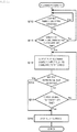
- the print control apparatus 4 outputs a discharge print request signal for effecting normal image formation to the head drive apparatus 3 and starts a print operation. Then, the carriage 2 having the heads 1 mounted thereon moves on the recording medium P along the main scanning direction. When the carriage 2 comes near to the image forming region, a print trigger signal is output to the print control apparatus 4 from the mechanical control apparatus 7 based on positional information detected and acquired by the encoder sensor 6. Upon inputting this print trigger signal, the print control apparatus 4 continuously outputs the print timing signal to each head drive apparatus 3. As a result, the head drive apparatus 3 discharges droplets from the nozzles of each head 1 based on the print timing signal and the image data from the print control apparatus 4 and forms an image corresponding to one line on the recording medium P along the main scanning direction.
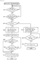
- the drive signal selection unit 32 keeps measuring a duration time of output of the oscillation timing signal in the time measurement unit 327 (S5). Furthermore, when the time comparison unit 328 detects that the duration time of this oscillation timing signal exceeds a set time that has been previously set (in case of Yes at S5), the drive signal selection unit 32 outputs a discharge signal request signal to the control unit 311 of the drive signal output unit 31 from the discharge signal request unit 322 and outputs a stop request signal to the meniscus oscillation signal cycle generation unit 326. As a result, the output of the oscillation timing signal is stopped (S6) .
- the drive signal selection unit 32 likewise outputs the stop request signal to the meniscus oscillation signal cycle generation unit 326 and stops the oscillation timing signal.
- the print trigger signal is again output to the print control apparatus 4 from the mechanical control apparatus 7 based on positional information detected and acquired by the encoder sensor 6. Further, like the above example, droplets are discharged from the nozzles of each head 1, and the image corresponding to one line is formed along the main scanning direction.
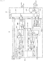
- FIG. 12 show an example of an internal configuration of the head drive apparatus 3 alone. Since portions designated by the same reference numerals as those in FIG. 4 and FIG. 10 represent portions having the same configurations, explanation thereof will be used, a description here will be omitted.
Landscapes
- Ink Jet (AREA)
Claims (4)
- Unité d'entraînement de tête comprenant;une tête à jet d'encre (1) entraînée basée sur un signal d'entraînement; etun appareil d'entraînement de tête (3) qui fait sortir un signal de décharge à la tête à jet d'encre basé sur les données d'image et un signal de synchronisation d'impression qui sont introduits d'un appareil extérieur, et celui décharge une gouttelette d'une buse pour former une image sur un milieu d'enregistrement,où l'appareil d'entraînement de tête (3) comprend:caractérisée en ce que,une unité de sortie de signal d'entraînement (31) pour faire sortir le signal de décharge utilisé pour décharger une gouttelette de la buse pour former une image et un signal d'oscillation de ménisque utilisé pour osciller le ménisque à un bout de la buse sans décharger une gouttelette de la buse comme un signal d'entraînement à la tête à jet d'encre;une unité de génération de cycle (326) pour générer un signal de synchronisation d'oscillation cyclique pour le signal d'oscillation de ménisque;une unité de détection d'interruption d'entrée (324) pour détecter qu'aucune entrée n'est faite et l'entrée du signal de synchronisation d'impression est interrompue même si un temps réglé en préalable s'est écoulé en surveillant l'entrée du signal de synchronisation d'impression; etune unité de sélection de signal d'entraînement (32), qui est configurée pour sélectionner le signal d'oscillation de ménisque comme le signal d'entraînement sorti de l'unité de sortie de signal d'entraînement et appliquer de manière continue le signal d'oscillation de ménisque à tous les buses de la tête à jet d'encre (1) en synchronisation avec le signal de synchronisation d'oscillation quand l'unité de détection d'interruption d'entrée (324) détecte que l'entrée du signal de synchronisation d'impression a été interrompue,l'unité d'entraînement de tête est ainsi configurée qu'alors quand un chariot (2) est présent dans la région de formation d'image, le ménisque en chaque buse est oscillé en interposant le signal d'oscillation de ménisque avant ou après le signal de synchronisation d'impression.
- Unité d'entraînement de tête selon la revendication 1, où l'unité de sélection de signal d'entraînement (32) a une unité de mesure de synchronisation (327) pour mesurer une durée de temps de sortie du signal d'oscillation de ménisque, et il arrête le signal d'oscillation de ménisque et commute le signal d'entrainement au signal de décharge quand le signal d'oscillation de ménisque est sélectionné comme le signal d'entraînement et ensuite l'unité de mesure de temps mesure l'écoulement d'un temps établi en préalable.
- Unité d'entraînement de tête selon la revendication 1, où l'unité de sélection de signal d'entraînement (32) a une unité de mesure de nombre de fois (327') pour mesurer le nombre de fois de sortie pour le signal d'oscillation de ménisque, et celle-ci arrête le signal d'oscillation de ménisque et commute le signal d'entrainement au signal de décharge quand le signal d'oscillation de ménisque est sélectionné comme le signal d'entraînement et ensuite l'unité de mesure de nombre de fois mesure un nombre de fois établi en préalable de sorties pour le signal sélectionné.
- Imprimante à jet d'encre (100) comprenant:une unité d'entraînement de tête (3) selon l'une quelconque des revendications 1 à 3;un appareil de transport de milieu d'enregistrement pour transporter le milieu d'enregistrement dans une direction de sous-balayage;un appareil de mouvement de tête pour mouvoir la tête à jet d'encre dans une direction de balayage principale croissant une direction de transport du milieu d'enregistrement;un appareil de détection d'information positionnelle (6) pour détecter l'information positionnelle de la tête à jet d'encre relative au milieu d'enregistrement; etun appareil de contrôle d'impression (4) qui fait sortir de manière continue les données d'image et le signal de synchronisation d'impression à l'appareil d'entraînement de tête basée sur l'information positionnelle détectée par l'appareil de détection d'information positionnelle seulement quand la tête à jet d'encre est présente dans une région de formation d'image pour le milieu d'enregistrement.
Applications Claiming Priority (2)
| Application Number | Priority Date | Filing Date | Title |
|---|---|---|---|
| JP2012118845 | 2012-05-24 | ||
| PCT/JP2013/064482 WO2013176253A1 (fr) | 2012-05-24 | 2013-05-24 | Unité d'entraînement de tête et imprimante à jet d'encre |
Publications (3)
| Publication Number | Publication Date |
|---|---|
| EP2857202A1 EP2857202A1 (fr) | 2015-04-08 |
| EP2857202A4 EP2857202A4 (fr) | 2016-10-19 |
| EP2857202B1 true EP2857202B1 (fr) | 2019-02-20 |
Family
ID=49623933
Family Applications (1)
| Application Number | Title | Priority Date | Filing Date |
|---|---|---|---|
| EP13794021.9A Active EP2857202B1 (fr) | 2012-05-24 | 2013-05-24 | Unité d'entraînement de tête et imprimante à jet d'encre |
Country Status (5)
| Country | Link |
|---|---|
| US (1) | US9289981B2 (fr) |
| EP (1) | EP2857202B1 (fr) |
| JP (1) | JP6264286B2 (fr) |
| CN (1) | CN104321197B (fr) |
| WO (1) | WO2013176253A1 (fr) |
Families Citing this family (7)
| Publication number | Priority date | Publication date | Assignee | Title |
|---|---|---|---|---|
| JP2015157433A (ja) * | 2014-02-25 | 2015-09-03 | 株式会社リコー | インク吐出装置、制御装置およびインク吐出制御方法 |
| JP6443164B2 (ja) * | 2015-03-24 | 2018-12-26 | セイコーエプソン株式会社 | 印刷データ生成装置、印刷装置、印刷データ生成方法およびプログラム |
| JP7135751B2 (ja) | 2018-11-13 | 2022-09-13 | 株式会社リコー | 液体循環装置、液体を吐出する装置 |
| DE102020129905A1 (de) * | 2020-11-12 | 2022-05-12 | Canon Production Printing Holding B.V. | Steuereinheit und Verfahren zur Erzeugung von Vorausstoß-Pulsen während einer Druckpause |
| US12002265B2 (en) | 2021-06-24 | 2024-06-04 | Xerox Corporation | Characterizing liquid reflective surfaces in 3D liquid metal printing |
| US11958112B2 (en) * | 2021-06-24 | 2024-04-16 | Xerox Corporation | Characterizing liquid reflective surfaces in 3D liquid metal printing |
| KR102650050B1 (ko) * | 2021-08-24 | 2024-03-20 | 세메스 주식회사 | 메니스커스 측정 장치 및 방법, 기판 처리 장치 |
Family Cites Families (11)
| Publication number | Priority date | Publication date | Assignee | Title |
|---|---|---|---|---|
| JP3556794B2 (ja) | 1997-03-11 | 2004-08-25 | コニカミノルタホールディングス株式会社 | インクジェットプリンタ |
| JP3611177B2 (ja) * | 1998-07-22 | 2005-01-19 | セイコーエプソン株式会社 | インクジェット式記録装置及び記録方法 |
| JP2000280555A (ja) | 1999-03-31 | 2000-10-10 | Minolta Co Ltd | 画像形成装置 |
| ATE409587T1 (de) * | 2001-08-29 | 2008-10-15 | Seiko Epson Corp | Flüssigkeitsstrahlvorrichtung und verfahren zu deren steuerung |
| JP4345346B2 (ja) | 2003-05-02 | 2009-10-14 | セイコーエプソン株式会社 | 静電式インクジェットヘッドの駆動方法、及びインクジェットプリンタ |
| JP2005104107A (ja) * | 2003-10-02 | 2005-04-21 | Seiko Epson Corp | 液体噴射装置、及び、その微振動制御方法 |
| JP4075780B2 (ja) * | 2003-11-27 | 2008-04-16 | ブラザー工業株式会社 | インクジェット記録装置 |
| JP4506427B2 (ja) | 2004-11-19 | 2010-07-21 | セイコーエプソン株式会社 | 液体噴射装置 |
| JP5272292B2 (ja) | 2006-05-30 | 2013-08-28 | コニカミノルタ株式会社 | インクジェット記録装置 |
| JP2007331117A (ja) * | 2006-06-12 | 2007-12-27 | Fuji Xerox Co Ltd | 液滴吐出ヘッド、及びこれを備えた画像形成装置 |
| JP5092791B2 (ja) | 2008-02-22 | 2012-12-05 | コニカミノルタIj株式会社 | インクジェット記録装置 |
-
2013
- 2013-05-24 EP EP13794021.9A patent/EP2857202B1/fr active Active
- 2013-05-24 US US14/403,447 patent/US9289981B2/en not_active Expired - Fee Related
- 2013-05-24 CN CN201380026214.XA patent/CN104321197B/zh active Active
- 2013-05-24 JP JP2014516864A patent/JP6264286B2/ja active Active
- 2013-05-24 WO PCT/JP2013/064482 patent/WO2013176253A1/fr not_active Ceased
Non-Patent Citations (1)
| Title |
|---|
| None * |
Also Published As
| Publication number | Publication date |
|---|---|
| US9289981B2 (en) | 2016-03-22 |
| EP2857202A1 (fr) | 2015-04-08 |
| US20150174898A1 (en) | 2015-06-25 |
| WO2013176253A1 (fr) | 2013-11-28 |
| JPWO2013176253A1 (ja) | 2016-01-14 |
| EP2857202A4 (fr) | 2016-10-19 |
| CN104321197A (zh) | 2015-01-28 |
| CN104321197B (zh) | 2016-08-17 |
| JP6264286B2 (ja) | 2018-01-24 |
Similar Documents
| Publication | Publication Date | Title |
|---|---|---|
| US9289981B2 (en) | Head drive unit and inkjet printer | |
| US8585175B2 (en) | Nozzle state detecting apparatus and image forming apparatus | |
| US8136917B2 (en) | Image forming apparatus and image forming system | |
| JP2004082629A (ja) | 記録装置及び予備吐出制御方法 | |
| EP2617571B1 (fr) | Dispositif d'enregistrement à jet d'encre pour l'éjection d'encre stable | |
| JP3659494B2 (ja) | 液体噴射装置 | |
| US9669620B2 (en) | Liquid droplet ejecting device, image forming apparatus, and method for detecting abnormal ejection of liquid droplet ejecting head | |
| US9969168B2 (en) | Recording apparatus, recording system, and maintenance method for recording apparatus | |
| JP2013237210A (ja) | 液体吐出装置、検査方法、及び、プログラム | |
| JP2004230847A (ja) | インクジェット記録装置 | |
| JP2005104107A (ja) | 液体噴射装置、及び、その微振動制御方法 | |
| JP6598602B2 (ja) | インクジェット印刷システムの複数のノズルのうちの第1ノズルのためのアクチュエータを駆動するための方法 | |
| JP2011088413A (ja) | 液体吐出装置及び液体吐出方法 | |
| JP2011046077A (ja) | 液体吐出装置及び液体吐出方法 | |
| JP2010173189A (ja) | 液体噴射装置、及び、液体噴射方法 | |
| JP4967893B2 (ja) | 液体噴射装置の駆動電圧再設定方法、及び、液体噴射装置 | |
| JP2005254709A (ja) | 液体噴射装置、及びその制御方法 | |
| JP2006076223A (ja) | インクジェット記録装置、そのヘッド温度制御方法、及びそのヘッド温度制御プログラム | |
| KR100579521B1 (ko) | 잉크젯 프린터의 인쇄 제어방법 | |
| US11529810B2 (en) | Liquid ejecting apparatus and controlling method for the same | |
| JP4956901B2 (ja) | 液体噴射装置 | |
| JP2011088368A (ja) | 液体吐出装置及び液体吐出方法 | |
| US20130050318A1 (en) | Printing apparatus | |
| JP2013000962A (ja) | インクジェット記録装置及びそのメンテナンス方法 | |
| JP2006272770A (ja) | 記録装置及び記録装置の制御方法 |
Legal Events
| Date | Code | Title | Description |
|---|---|---|---|
| PUAI | Public reference made under article 153(3) epc to a published international application that has entered the european phase |
Free format text: ORIGINAL CODE: 0009012 |
|
| 17P | Request for examination filed |
Effective date: 20141113 |
|
| AK | Designated contracting states |
Kind code of ref document: A1 Designated state(s): AL AT BE BG CH CY CZ DE DK EE ES FI FR GB GR HR HU IE IS IT LI LT LU LV MC MK MT NL NO PL PT RO RS SE SI SK SM TR |
|
| AX | Request for extension of the european patent |
Extension state: BA ME |
|
| DAX | Request for extension of the european patent (deleted) | ||
| RA4 | Supplementary search report drawn up and despatched (corrected) |
Effective date: 20160915 |
|
| RIC1 | Information provided on ipc code assigned before grant |
Ipc: B41J 2/01 20060101AFI20160909BHEP Ipc: B41J 2/175 20060101ALI20160909BHEP |
|
| STAA | Information on the status of an ep patent application or granted ep patent |
Free format text: STATUS: EXAMINATION IS IN PROGRESS |
|
| 17Q | First examination report despatched |
Effective date: 20180329 |
|
| GRAP | Despatch of communication of intention to grant a patent |
Free format text: ORIGINAL CODE: EPIDOSNIGR1 |
|
| STAA | Information on the status of an ep patent application or granted ep patent |
Free format text: STATUS: GRANT OF PATENT IS INTENDED |
|
| INTG | Intention to grant announced |
Effective date: 20181107 |
|
| GRAS | Grant fee paid |
Free format text: ORIGINAL CODE: EPIDOSNIGR3 |
|
| GRAA | (expected) grant |
Free format text: ORIGINAL CODE: 0009210 |
|
| STAA | Information on the status of an ep patent application or granted ep patent |
Free format text: STATUS: THE PATENT HAS BEEN GRANTED |
|
| AK | Designated contracting states |
Kind code of ref document: B1 Designated state(s): AL AT BE BG CH CY CZ DE DK EE ES FI FR GB GR HR HU IE IS IT LI LT LU LV MC MK MT NL NO PL PT RO RS SE SI SK SM TR |
|
| REG | Reference to a national code |
Ref country code: GB Ref legal event code: FG4D |
|
| REG | Reference to a national code |
Ref country code: CH Ref legal event code: EP |
|
| REG | Reference to a national code |
Ref country code: DE Ref legal event code: R096 Ref document number: 602013051042 Country of ref document: DE |
|
| REG | Reference to a national code |
Ref country code: AT Ref legal event code: REF Ref document number: 1097666 Country of ref document: AT Kind code of ref document: T Effective date: 20190315 |
|
| REG | Reference to a national code |
Ref country code: IE Ref legal event code: FG4D |
|
| REG | Reference to a national code |
Ref country code: NL Ref legal event code: MP Effective date: 20190220 |
|
| REG | Reference to a national code |
Ref country code: LT Ref legal event code: MG4D |
|
| PG25 | Lapsed in a contracting state [announced via postgrant information from national office to epo] |
Ref country code: FI Free format text: LAPSE BECAUSE OF FAILURE TO SUBMIT A TRANSLATION OF THE DESCRIPTION OR TO PAY THE FEE WITHIN THE PRESCRIBED TIME-LIMIT Effective date: 20190220 Ref country code: LT Free format text: LAPSE BECAUSE OF FAILURE TO SUBMIT A TRANSLATION OF THE DESCRIPTION OR TO PAY THE FEE WITHIN THE PRESCRIBED TIME-LIMIT Effective date: 20190220 Ref country code: NL Free format text: LAPSE BECAUSE OF FAILURE TO SUBMIT A TRANSLATION OF THE DESCRIPTION OR TO PAY THE FEE WITHIN THE PRESCRIBED TIME-LIMIT Effective date: 20190220 Ref country code: PT Free format text: LAPSE BECAUSE OF FAILURE TO SUBMIT A TRANSLATION OF THE DESCRIPTION OR TO PAY THE FEE WITHIN THE PRESCRIBED TIME-LIMIT Effective date: 20190620 Ref country code: NO Free format text: LAPSE BECAUSE OF FAILURE TO SUBMIT A TRANSLATION OF THE DESCRIPTION OR TO PAY THE FEE WITHIN THE PRESCRIBED TIME-LIMIT Effective date: 20190520 Ref country code: SE Free format text: LAPSE BECAUSE OF FAILURE TO SUBMIT A TRANSLATION OF THE DESCRIPTION OR TO PAY THE FEE WITHIN THE PRESCRIBED TIME-LIMIT Effective date: 20190220 |
|
| PG25 | Lapsed in a contracting state [announced via postgrant information from national office to epo] |
Ref country code: LV Free format text: LAPSE BECAUSE OF FAILURE TO SUBMIT A TRANSLATION OF THE DESCRIPTION OR TO PAY THE FEE WITHIN THE PRESCRIBED TIME-LIMIT Effective date: 20190220 Ref country code: RS Free format text: LAPSE BECAUSE OF FAILURE TO SUBMIT A TRANSLATION OF THE DESCRIPTION OR TO PAY THE FEE WITHIN THE PRESCRIBED TIME-LIMIT Effective date: 20190220 Ref country code: HR Free format text: LAPSE BECAUSE OF FAILURE TO SUBMIT A TRANSLATION OF THE DESCRIPTION OR TO PAY THE FEE WITHIN THE PRESCRIBED TIME-LIMIT Effective date: 20190220 Ref country code: IS Free format text: LAPSE BECAUSE OF FAILURE TO SUBMIT A TRANSLATION OF THE DESCRIPTION OR TO PAY THE FEE WITHIN THE PRESCRIBED TIME-LIMIT Effective date: 20190620 Ref country code: BG Free format text: LAPSE BECAUSE OF FAILURE TO SUBMIT A TRANSLATION OF THE DESCRIPTION OR TO PAY THE FEE WITHIN THE PRESCRIBED TIME-LIMIT Effective date: 20190520 Ref country code: GR Free format text: LAPSE BECAUSE OF FAILURE TO SUBMIT A TRANSLATION OF THE DESCRIPTION OR TO PAY THE FEE WITHIN THE PRESCRIBED TIME-LIMIT Effective date: 20190521 |
|
| REG | Reference to a national code |
Ref country code: AT Ref legal event code: MK05 Ref document number: 1097666 Country of ref document: AT Kind code of ref document: T Effective date: 20190220 |
|
| PG25 | Lapsed in a contracting state [announced via postgrant information from national office to epo] |
Ref country code: DK Free format text: LAPSE BECAUSE OF FAILURE TO SUBMIT A TRANSLATION OF THE DESCRIPTION OR TO PAY THE FEE WITHIN THE PRESCRIBED TIME-LIMIT Effective date: 20190220 Ref country code: SK Free format text: LAPSE BECAUSE OF FAILURE TO SUBMIT A TRANSLATION OF THE DESCRIPTION OR TO PAY THE FEE WITHIN THE PRESCRIBED TIME-LIMIT Effective date: 20190220 Ref country code: ES Free format text: LAPSE BECAUSE OF FAILURE TO SUBMIT A TRANSLATION OF THE DESCRIPTION OR TO PAY THE FEE WITHIN THE PRESCRIBED TIME-LIMIT Effective date: 20190220 Ref country code: RO Free format text: LAPSE BECAUSE OF FAILURE TO SUBMIT A TRANSLATION OF THE DESCRIPTION OR TO PAY THE FEE WITHIN THE PRESCRIBED TIME-LIMIT Effective date: 20190220 Ref country code: CZ Free format text: LAPSE BECAUSE OF FAILURE TO SUBMIT A TRANSLATION OF THE DESCRIPTION OR TO PAY THE FEE WITHIN THE PRESCRIBED TIME-LIMIT Effective date: 20190220 Ref country code: AL Free format text: LAPSE BECAUSE OF FAILURE TO SUBMIT A TRANSLATION OF THE DESCRIPTION OR TO PAY THE FEE WITHIN THE PRESCRIBED TIME-LIMIT Effective date: 20190220 Ref country code: EE Free format text: LAPSE BECAUSE OF FAILURE TO SUBMIT A TRANSLATION OF THE DESCRIPTION OR TO PAY THE FEE WITHIN THE PRESCRIBED TIME-LIMIT Effective date: 20190220 |
|
| REG | Reference to a national code |
Ref country code: DE Ref legal event code: R097 Ref document number: 602013051042 Country of ref document: DE |
|
| PG25 | Lapsed in a contracting state [announced via postgrant information from national office to epo] |
Ref country code: SM Free format text: LAPSE BECAUSE OF FAILURE TO SUBMIT A TRANSLATION OF THE DESCRIPTION OR TO PAY THE FEE WITHIN THE PRESCRIBED TIME-LIMIT Effective date: 20190220 Ref country code: PL Free format text: LAPSE BECAUSE OF FAILURE TO SUBMIT A TRANSLATION OF THE DESCRIPTION OR TO PAY THE FEE WITHIN THE PRESCRIBED TIME-LIMIT Effective date: 20190220 |
|
| REG | Reference to a national code |
Ref country code: DE Ref legal event code: R119 Ref document number: 602013051042 Country of ref document: DE |
|
| PLBE | No opposition filed within time limit |
Free format text: ORIGINAL CODE: 0009261 |
|
| STAA | Information on the status of an ep patent application or granted ep patent |
Free format text: STATUS: NO OPPOSITION FILED WITHIN TIME LIMIT |
|
| REG | Reference to a national code |
Ref country code: CH Ref legal event code: PL |
|
| PG25 | Lapsed in a contracting state [announced via postgrant information from national office to epo] |
Ref country code: AT Free format text: LAPSE BECAUSE OF FAILURE TO SUBMIT A TRANSLATION OF THE DESCRIPTION OR TO PAY THE FEE WITHIN THE PRESCRIBED TIME-LIMIT Effective date: 20190220 |
|
| 26N | No opposition filed |
Effective date: 20191121 |
|
| GBPC | Gb: european patent ceased through non-payment of renewal fee |
Effective date: 20190524 |
|
| PG25 | Lapsed in a contracting state [announced via postgrant information from national office to epo] |
Ref country code: LI Free format text: LAPSE BECAUSE OF NON-PAYMENT OF DUE FEES Effective date: 20190531 Ref country code: MC Free format text: LAPSE BECAUSE OF FAILURE TO SUBMIT A TRANSLATION OF THE DESCRIPTION OR TO PAY THE FEE WITHIN THE PRESCRIBED TIME-LIMIT Effective date: 20190220 Ref country code: CH Free format text: LAPSE BECAUSE OF NON-PAYMENT OF DUE FEES Effective date: 20190531 |
|
| REG | Reference to a national code |
Ref country code: BE Ref legal event code: MM Effective date: 20190531 |
|
| PG25 | Lapsed in a contracting state [announced via postgrant information from national office to epo] |
Ref country code: LU Free format text: LAPSE BECAUSE OF NON-PAYMENT OF DUE FEES Effective date: 20190524 Ref country code: SI Free format text: LAPSE BECAUSE OF FAILURE TO SUBMIT A TRANSLATION OF THE DESCRIPTION OR TO PAY THE FEE WITHIN THE PRESCRIBED TIME-LIMIT Effective date: 20190220 |
|
| PG25 | Lapsed in a contracting state [announced via postgrant information from national office to epo] |
Ref country code: TR Free format text: LAPSE BECAUSE OF FAILURE TO SUBMIT A TRANSLATION OF THE DESCRIPTION OR TO PAY THE FEE WITHIN THE PRESCRIBED TIME-LIMIT Effective date: 20190220 |
|
| PG25 | Lapsed in a contracting state [announced via postgrant information from national office to epo] |
Ref country code: DE Free format text: LAPSE BECAUSE OF NON-PAYMENT OF DUE FEES Effective date: 20191203 Ref country code: IE Free format text: LAPSE BECAUSE OF NON-PAYMENT OF DUE FEES Effective date: 20190524 Ref country code: GB Free format text: LAPSE BECAUSE OF NON-PAYMENT OF DUE FEES Effective date: 20190524 |
|
| PG25 | Lapsed in a contracting state [announced via postgrant information from national office to epo] |
Ref country code: BE Free format text: LAPSE BECAUSE OF NON-PAYMENT OF DUE FEES Effective date: 20190531 |
|
| PG25 | Lapsed in a contracting state [announced via postgrant information from national office to epo] |
Ref country code: FR Free format text: LAPSE BECAUSE OF NON-PAYMENT OF DUE FEES Effective date: 20190531 |
|
| PG25 | Lapsed in a contracting state [announced via postgrant information from national office to epo] |
Ref country code: CY Free format text: LAPSE BECAUSE OF FAILURE TO SUBMIT A TRANSLATION OF THE DESCRIPTION OR TO PAY THE FEE WITHIN THE PRESCRIBED TIME-LIMIT Effective date: 20190220 |
|
| PG25 | Lapsed in a contracting state [announced via postgrant information from national office to epo] |
Ref country code: HU Free format text: LAPSE BECAUSE OF FAILURE TO SUBMIT A TRANSLATION OF THE DESCRIPTION OR TO PAY THE FEE WITHIN THE PRESCRIBED TIME-LIMIT; INVALID AB INITIO Effective date: 20130524 Ref country code: MT Free format text: LAPSE BECAUSE OF FAILURE TO SUBMIT A TRANSLATION OF THE DESCRIPTION OR TO PAY THE FEE WITHIN THE PRESCRIBED TIME-LIMIT Effective date: 20190220 |
|
| PG25 | Lapsed in a contracting state [announced via postgrant information from national office to epo] |
Ref country code: MK Free format text: LAPSE BECAUSE OF FAILURE TO SUBMIT A TRANSLATION OF THE DESCRIPTION OR TO PAY THE FEE WITHIN THE PRESCRIBED TIME-LIMIT Effective date: 20190220 |
|
| P01 | Opt-out of the competence of the unified patent court (upc) registered |
Effective date: 20230510 |
|
| PGFP | Annual fee paid to national office [announced via postgrant information from national office to epo] |
Ref country code: IT Payment date: 20250422 Year of fee payment: 13 |