EP2857231B1 - Antirutschvorrichtung für ein Fahrzeugrad - Google Patents
Antirutschvorrichtung für ein Fahrzeugrad Download PDFInfo
- Publication number
- EP2857231B1 EP2857231B1 EP14179313.3A EP14179313A EP2857231B1 EP 2857231 B1 EP2857231 B1 EP 2857231B1 EP 14179313 A EP14179313 A EP 14179313A EP 2857231 B1 EP2857231 B1 EP 2857231B1
- Authority
- EP
- European Patent Office
- Prior art keywords
- chain
- section
- ring
- folded
- edge
- Prior art date
- Legal status (The legal status is an assumption and is not a legal conclusion. Google has not performed a legal analysis and makes no representation as to the accuracy of the status listed.)
- Active
Links
Images


Classifications
-
- B—PERFORMING OPERATIONS; TRANSPORTING
- B60—VEHICLES IN GENERAL
- B60C—VEHICLE TYRES; TYRE INFLATION; TYRE CHANGING; CONNECTING VALVES TO INFLATABLE ELASTIC BODIES IN GENERAL; DEVICES OR ARRANGEMENTS RELATED TO TYRES
- B60C27/00—Non-skid devices temporarily attachable to resilient tyres or resiliently-tyred wheels
- B60C27/06—Non-skid devices temporarily attachable to resilient tyres or resiliently-tyred wheels extending over the complete circumference of the tread, e.g. made of chains or cables
- B60C27/08—Non-skid devices temporarily attachable to resilient tyres or resiliently-tyred wheels extending over the complete circumference of the tread, e.g. made of chains or cables involving lugs or rings taking up wear, e.g. chain links, chain connectors
Definitions
- the present invention relates to an anti-skid device for a vehicle wheel (a snow chain).
- Snow chains are known comprising:
- This fastening system comprises:
- Such a pin allows the rotation of an end link of one of said sections of chain with respect to the fastening system.
- snow chains are for example shown in document US1424347 .
- the technical task underpinning the present invention is herein to provide an anti-skid device for a vehicle wheel that allows component optimization, i.e. determining a reduction in costs and production times. It is a further object of this text to provide a strong and durable anti-skid device.
- reference number 1 designates an anti-skid device for a vehicle wheel. It is used to stop or however reduce the skidding of a vehicle in case of snow.
- a device 1 comprises a ring 2 designed to abut a lateral portion of a tyre (or however of a wheel). Particularly such a ring 2 is designed to abut a lateral inner portion of the tyre or however of the wheel (i.e. the part facing inwards to the vehicle). Appropriately such a ring 2 develops almost coaxially with the tyre.
- Such a ring 2 appropriately comprises a metal core potentially covered in some sections with a plastic coating.
- Such a ring can be opened to allow the positioning and/or removal of the device 1 with respect to the wheel.
- a connector that allows two ends of said ring 2 to be mutually constrained/released.
- the device 1 further comprises a first section 3 of anti-skid chain, at least one part of which is designed to overlap a tread of a tyre. A part of the first section 3 of chain also overlaps a shoulder of the tyre. Such first section 3 of the chain is designed to remain at least partially interposed between the ground and the tyre and to exert an anti-skid action.
- the device 1 further comprises fastening means 4 for fastening said first section 3 of chain to said ring 2.
- the fastening means 4 are connected to said core of the ring 2.
- the ring 2 is free from the plastic coating.
- Such plastic coating therefore defines positioning means of the fastening means 4 along the extension of the core. By causing a ring thickening, the plastic coating holds or contributes to hold the fastening means 4 in position.
- the fastening means 4 comprises a body 5 made as a single piece.
- the body 5 is a single block. It is completely made of the same material.
- the body 5 does not therefore define an assembled item made of various components or parts. It extends continuously.
- Such a body 5 advantageously comprises:
- the first portion 51 defines a first seat 513 that receives one part of said ring 2.
- the second portion 52 defines a second seat 514 that is distinguished from the first seat 513 and receives one part of said end link 30 of the first section 3 of chain. It is specified that said first section 3 of chain needs not necessarily to have all equal links. In fact, they may have different shapes and sizes. In particular the end link 30 may have a different shape and/or size if compared to the immediately subsequent one.
- the first and the second seat 513, 514 can extend along substantially parallel longitudinal axes. Appropriately the first seat 513 extends along its own longitudinal axis by less than 2 centimetres.
- the second seat 514 extends along its own longitudinal axis by less than 1 centimetre, preferably less than 5 millimetres.
- the body 5 coincides with a thin folded plate 50.
- the thickness of such a plate 50 is less than 2 millimetres, preferably about 1 millimetre.
- the end link 30 of the first section 3 of chain clasps a part of said thin folded plate 50.
- the end link 30 can rotate about said thin folded plate 50.
- the end link 30 is a closed ring.
- the body 5, in particular the thin plate 50 is made of metal material.
- the body 5, in particular the thin plate 50 is rigid.
- the second connection portion 52 comprises an edge 520 that is folded so as to define a channel 521 for passage of the end link 30.
- Such a channel can be substantially shaped like an oval based prism.
- An end of said edge 520 is welded to remaining parts of the body 5 over which said edge 520 is folded. This enables the chain to be made stronger. Furthermore also the assembly can take place quickly without the need for further accessory components such as, for example, assembly pins or the like.
- the first connection portion 51 comprises/coincides with a hooked fastener 510.
- a fastener 510 is wound around a section of the ring 2, in particular a section of the core of the ring 2.
- the end link 30 of the first section 3 of chain may be flat and not twisted.
- the first section 3 comprises a plurality of twisted links.
- the twisted links are consecutive to the end link 30.
- the use of twisted links is particularly advantageous since it makes it possible to produce chains that can be used also in sports cars in which there is a reduced space between the tyre and the mechanical organs of the vehicle (suspensions, etc.).
- snow chains can be assembled even if the minimum space between the tyre and the mechanical organs of the vehicle is greater than 7 or 8 millimetres.
- the portion of the chain that overlaps with a lateral side of the tyre remains between the lateral side of the tyre and a plane parallel to it 7 or 8 millimetres away.
- the first connection portion 51 comprises a folded flap 511 for defining said first seat 513 which receives one part of said ring 2.
- one end 512 of said flap 511 is near, but not welded (and more generally not directly connected) to one part of said body 5 over which the flap 511 is folded.
- the flap 511 therefore remains alongside a part of said body 5 over which the flap 511 is folded.
- the flap 511 allows the ring 2 to be fastened. After the positioning around a part of the ring 2 such a flap 511 is normally clamped around said part of the ring 2.
- the flap 511 can however normally rotate with respect to the ring 2, in particular with respect to the core of the ring 2.
- the first and the second portion 51, 52 of the body 5 are located at two opposite sides of said body 5.
- said body 5 comprises a flat metal zone interposed between the first and the second portion 51, 52.
- such flat zone extends parallel to the plane identified by said ring 2.
- the device 1 comprises a second section 6 of anti-skid chain designed to at least partially overlap a tread of a tyre.
- the body 5 made as a single piece (in particular the thin plate 50) comprises a third connection portion 53 in which an end link 60 of the second section 6 of chain is engaged.
- One or more of the characteristics described with reference to the connection of the first portion 51 of the end link 30 can be repeated for the connection of the third portion 53 of the end link 60.
- the third connection portion 53 comprises an additional folded edge 530 so as to define a channel for passage of said end link 60 of the second section 6 of the chain; one end of said additional edge 530 being welded to remaining parts of the body 5 over which said additional edge 530 is folded.
- the folded edge 530 therefore defines a third seat 533 designed to be crossed by the end link 60 of the second section of chain.
- the second and the third seat 514, 533 are alongside one another.
- the second and the third seat 514, 533 could be coaxial.
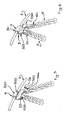
- Such a solution is exemplified in figures 5 and 6 , where two distinct sections of chain are connected with the same body 5.
- fastening means 4 may be fastened to a single chain (see figures 3 and 4 ), whereas others may be fastened to two chains (see figures 5 and 6 ).
- the device 1 comprises an annular structure 7 designed to abut a lateral portion of a wheel facing outwards from the vehicle.
- the first section 3 extends between the ring 2 and said annular structure 7.
- the device 1 comprises a plurality of modular elements 8 of anti-skid chains which in turn comprise:
- connection rings 84 At the intersection points of the two transversal portions 81, 82 with the circumferential portion 83 there are circular connection rings 84.
- Such circular rings 84 appropriately have undulations in order to better interface with the twisted links that are connected to them.
- the circular shape of the circular ring 84 is important since it allows this junction zone to be reinforced with respect to other shapes thereof.
- the links of said chains of modular elements 8 are appropriately partially twisted.
- first and the second section 3, 6 previously described are part of distinct and consecutive modular elements 8.
- the present invention further relates to a method for the production of an anti-skid device for a vehicle wheel having one or more of the characteristics previously described.
- the method comprises the steps of:
- the step of galvanizing the first section 3 of chain and said body 5 is integrated into a wider galvanizing step of a plurality of sections of anti-skid chain.
- the step of connecting said body 5 to said first section of chain 3 further envisages a step of welding an end of said edge 520 to remaining parts of the body 5 over which said edge 520 is folded.
- the method may also envisage a step of welding an end of said additional edge 530 to remaining parts of the body 5 over which said additional edge 530 is folded.
- the step of welding said end of the edge 520 (and/or the additional edge 530) takes place before said galvanizing step.
- the fact that the flap 511 is not welded to the body 5 after the folding makes it possible to galvanize the chain before the final assembly with the ring 2 (making the production process simpler and quicker).
- the present invention has numerous advantages.
Landscapes
- Engineering & Computer Science (AREA)
- Mechanical Engineering (AREA)
- Hand Tools For Fitting Together And Separating, Or Other Hand Tools (AREA)
- Lock And Its Accessories (AREA)
- Braking Arrangements (AREA)
Claims (9)
- Antirutschvorrichtung für ein Fahrzeugrad, umfassend:i) einen Ring (2), der ausgestaltet ist, um an einen seitlichen Abschnitt eines Rads eines Fahrzeugs anzuschlagen;ii) eine erste Sektion (3) einer Antirutschkette, von der ein Teil ausgelegt ist, um eine Lauffläche eines Reifens zumindest teilweise zu überlappen;iii) Befestigungsmittel (4) zum Befestigen der ersten Kettensektion (3) am Ring (2),wobei diese Befestigungsmittel (4) einen Körper (5) umfassen, der in einem einzigen Stück ausgebildet ist,
umfassend:- einen ersten Verbindungsabschnitt (51) zur Verbindung mit dem Ring (2);- einen zweiten Verbindungsabschnitt (52), in den ein Endglied (30) der ersten Kettensektion (3) eingreift, wobei der erste und der zweite Abschnitt (51, 52) jeweils einen ersten Sitz (513), der einen Teil des Rings (2) aufnimmt, und einen zweiten Sitz (514), der vom ersten Sitz (513) unterschieden ist und einen Teil des Endglieds (30) der ersten Kettensektion (3) aufnimmt, definieren,wobei der zweite Verbindungsabschnitt (52) eine Kante (520) umfasst, die so gefaltet ist, dass sie einen Kanal (521) für den Durchgang des Endglieds (30) der ersten Kettensektion (3) definiert,
wobei die Vorrichtung dadurch gekennzeichnet ist, dass ein Ende der Kante (520) an den übrigen Teilen des Körpers (5), über die die Kante (520) gefaltet ist, angeschweißt ist. - Vorrichtung nach Anspruch 1, dadurch gekennzeichnet, dass der Körper (5) mit einer dünnen gefalteten Platte (50) übereinstimmt, wobei das Glied (30) der ersten Kettensektion (3) einen Teil der dünnen gefalteten Platte (50) umspannt und in der Lage ist, sich um diesen zu drehen.
- Vorrichtung nach einem der vorhergehenden Ansprüche, dadurch gekennzeichnet, dass der erste Verbindungsabschnitt (51) einen Hakenverschluss (510) umfasst/mit diesem übereinstimmt.
- Vorrichtung nach einem der vorhergehenden Abschnitte, dadurch gekennzeichnet, dass das Endglied (30) der ersten Kettensektion (3) flach und nicht gewunden ist.
- Vorrichtung nach einem der vorhergehenden Ansprüche, dadurch gekennzeichnet, dass der erste Verbindungsabschnitt (51) eine gefaltete Klappe (511) umfasst, um den ersten Sitz (513) zu definieren, die einen Teil des Rings (2) aufnimmt, wobei ein Ende (512) dieser Klappe (511) sich nahe an einem Teil des Körpers (5) befindet, über den die Klappe (511) gefaltet ist, jedoch nicht mit diesem verschweißt ist.
- Vorrichtung nach einem der vorhergehenden Ansprüche, dadurch gekennzeichnet, dass sie eine zweite Sektion (6) einer Antirutschkette umfasst, die ausgestaltet ist, um eine Lauffläche eines Reifens zumindest teilweise zu überlappen, wobei der Körper (5) in einem einzigen Stück ausgebildet ist, umfassend einen dritten Verbindungsabschnitt (53), in den ein Endglied (60) der zweiten Kettensektion (6) eingreift.
- Vorrichtung nach Anspruch 6, dadurch gekennzeichnet, dass der dritte Verbindungsabschnitt (53) eine zusätzliche Kante (530) umfasst, die so gefaltet ist, dass sie einen Kanal für den Durchgang des Endglieds (60) der zweiten Kettensektion (6) definiert, wobei ein Ende der zusätzlichen Kante (530) an den übrigen Teilen des Körpers (5), über die die zusätzliche Kante (530) gefaltet ist, angeschweißt ist.
- Vorrichtung nach einem der vorhergehenden Ansprüche, dadurch gekennzeichnet, dass sie eine Ringstruktur (7) umfasst, die ausgestaltet ist, um an einem seitlichen Abschnitt eines Rads anzuschlagen, der zur Außenseite des Fahrzeugs hin gerichtet ist, wobei der erste Abschnitt (3) eine Vielzahl an gewundenen Glieder umfasst und sich zwischen dem Ring (2) und der Ringstruktur (7) erstreckt.
- Verfahren zur Herstellung einer Vorrichtung nach einem der vorhergehenden Abschnitte, dadurch gekennzeichnet, dass es folgende Schritte umfasst:- Verbinden des Körpers (5) mit der ersten Kettensektion (3);- Galvanisieren der ersten Kettensektion (3) und des Körpers (5);- nach der Galvanisierung Verbinden der ersten Kettensektion (3) mit dem Ring (2), wobei der erste Abschnitt (51) des Körpers rund um einen Teil des Rings (2) gefaltet wird,wobei der Schritt zum Verbinden des Körpers (5) mit der ersten Kettensektion (3) zudem einen Schritt zum Verschweißen eines Endes der Kante (520) an den übrigen Teilen des Körpers (5), über die die Kante (520) gefaltet wird, umfasst, und der Schritt zum Verschweißen des Endes der Kante (520) vor dem Schritt zum Galvanisieren stattfindet.
Applications Claiming Priority (1)
| Application Number | Priority Date | Filing Date | Title |
|---|---|---|---|
| IT000072A ITPR20130072A1 (it) | 2013-09-23 | 2013-09-23 | Dispositivo antislittamento per una ruota di un veicolo |
Publications (2)
| Publication Number | Publication Date |
|---|---|
| EP2857231A1 EP2857231A1 (de) | 2015-04-08 |
| EP2857231B1 true EP2857231B1 (de) | 2015-12-23 |
Family
ID=49640046
Family Applications (1)
| Application Number | Title | Priority Date | Filing Date |
|---|---|---|---|
| EP14179313.3A Active EP2857231B1 (de) | 2013-09-23 | 2014-07-31 | Antirutschvorrichtung für ein Fahrzeugrad |
Country Status (2)
| Country | Link |
|---|---|
| EP (1) | EP2857231B1 (de) |
| IT (1) | ITPR20130072A1 (de) |
Families Citing this family (1)
| Publication number | Priority date | Publication date | Assignee | Title |
|---|---|---|---|---|
| ITUB20154773A1 (it) | 2015-10-30 | 2017-04-30 | Lampa S P A | Dispositivo antislittamento per ruota di veicolo. |
Family Cites Families (7)
| Publication number | Priority date | Publication date | Assignee | Title |
|---|---|---|---|---|
| US1025159A (en) * | 1909-01-18 | 1912-05-07 | John W Pax | Chain-guard for vehicle-wheels. |
| US1424347A (en) | 1917-10-31 | 1922-08-01 | John H Evans | Antiskid device |
| US1679416A (en) * | 1927-09-07 | 1928-08-07 | Felger Bob | Quick-change link |
| FR767887A (de) * | 1937-03-19 | 1934-07-25 | ||
| US4615368A (en) * | 1984-10-30 | 1986-10-07 | Lagrand Chain Corporation | Apparatus for detachably fastening lateral cable in tire chain |
| IT250230Y1 (it) * | 2000-06-02 | 2003-07-28 | Konig Spa | Gancio di giunzione per collegare elementi di catene da neve |
| US9233584B2 (en) * | 2010-08-16 | 2016-01-12 | J. Scott Hanson | Tire chain and method of modifying a tire chain |
-
2013
- 2013-09-23 IT IT000072A patent/ITPR20130072A1/it unknown
-
2014
- 2014-07-31 EP EP14179313.3A patent/EP2857231B1/de active Active
Also Published As
| Publication number | Publication date |
|---|---|
| EP2857231A1 (de) | 2015-04-08 |
| ITPR20130072A1 (it) | 2015-03-24 |
Similar Documents
| Publication | Publication Date | Title |
|---|---|---|
| US9033139B2 (en) | Rod belt for a rod belt conveyor for agricultural machinery | |
| US20160107493A1 (en) | Cross member system for a coupling device a motor vehicle | |
| EP2857231B1 (de) | Antirutschvorrichtung für ein Fahrzeugrad | |
| JP2011500388A5 (de) | ||
| EA200970757A1 (ru) | Конструкция борта пневматической шины | |
| US20150202918A1 (en) | Adhesive-type wheel balance weight for vehicle and manufacturing method thereof | |
| PT3730354T (pt) | Sistema de almofada insuflável para um veículo e método de fabrico para o sistema de almofada insuflável | |
| CN100595082C (zh) | 具有有限体积的防滑链 | |
| US8833129B2 (en) | Motor vehicle pedals and manufacturing methods thereof | |
| EP3476621B1 (de) | Verbindungselement für fahrradfelgen, fahrradfelge mit solch einem verbindungselement und verfahren zur herstellung einer solchen felge | |
| EP1803591B1 (de) | System zur Befestigung eines Kettenstrangs an den Innenstrang einer Gleitschutzkette mit geringer Bauhöhe | |
| KR101022835B1 (ko) | 마스터 링크의 가공방법 | |
| WO2008024770B1 (en) | Wheels that have the appearance of multi-piece wheels | |
| EP3713860B1 (de) | Rohrseilförderschnecke mit integriertem verbinder | |
| RU2505422C1 (ru) | Устройство противоскольжения для шин | |
| CN114845884A (zh) | 车辆车轮和制备车辆车轮的方法 | |
| SU847903A3 (ru) | Цепь противоскольжени | |
| KR101295006B1 (ko) | 자동변속기의 드럼 부품 성형 방법 | |
| EP1719642B1 (de) | Luftreifen und Herstellungsverfahren | |
| EP2008838A1 (de) | Felgenkratzschutzvorrichtung für Schneeketten | |
| ATE439252T1 (de) | Reifen für schwerfahrzeuge | |
| US20080196248A1 (en) | Method for Producing an Exhaust-Carrying Device | |
| RU2019100793A (ru) | Соединительное звено гусеничной цепи и способ его изготовления | |
| US20130228257A1 (en) | Chain for mounting on a vehicle tire | |
| ITUB20154773A1 (it) | Dispositivo antislittamento per ruota di veicolo. |
Legal Events
| Date | Code | Title | Description |
|---|---|---|---|
| PUAI | Public reference made under article 153(3) epc to a published international application that has entered the european phase |
Free format text: ORIGINAL CODE: 0009012 |
|
| 17P | Request for examination filed |
Effective date: 20140731 |
|
| AK | Designated contracting states |
Kind code of ref document: A1 Designated state(s): AL AT BE BG CH CY CZ DE DK EE ES FI FR GB GR HR HU IE IS IT LI LT LU LV MC MK MT NL NO PL PT RO RS SE SI SK SM TR |
|
| AX | Request for extension of the european patent |
Extension state: BA ME |
|
| RIN1 | Information on inventor provided before grant (corrected) |
Inventor name: MARUTTI, PAOLO |
|
| RIC1 | Information provided on ipc code assigned before grant |
Ipc: B60C 27/08 20060101AFI20150601BHEP |
|
| GRAP | Despatch of communication of intention to grant a patent |
Free format text: ORIGINAL CODE: EPIDOSNIGR1 |
|
| INTG | Intention to grant announced |
Effective date: 20150924 |
|
| GRAS | Grant fee paid |
Free format text: ORIGINAL CODE: EPIDOSNIGR3 |
|
| GRAA | (expected) grant |
Free format text: ORIGINAL CODE: 0009210 |
|
| AK | Designated contracting states |
Kind code of ref document: B1 Designated state(s): AL AT BE BG CH CY CZ DE DK EE ES FI FR GB GR HR HU IE IS IT LI LT LU LV MC MK MT NL NO PL PT RO RS SE SI SK SM TR |
|
| REG | Reference to a national code |
Ref country code: GB Ref legal event code: FG4D |
|
| REG | Reference to a national code |
Ref country code: CH Ref legal event code: EP |
|
| REG | Reference to a national code |
Ref country code: IE Ref legal event code: FG4D |
|
| REG | Reference to a national code |
Ref country code: AT Ref legal event code: REF Ref document number: 766381 Country of ref document: AT Kind code of ref document: T Effective date: 20160115 |
|
| REG | Reference to a national code |
Ref country code: DE Ref legal event code: R096 Ref document number: 602014000607 Country of ref document: DE |
|
| REG | Reference to a national code |
Ref country code: CH Ref legal event code: NV Representative=s name: BUGNION S.A., CH |
|
| REG | Reference to a national code |
Ref country code: LT Ref legal event code: MG4D |
|
| REG | Reference to a national code |
Ref country code: NL Ref legal event code: MP Effective date: 20151223 |
|
| PG25 | Lapsed in a contracting state [announced via postgrant information from national office to epo] |
Ref country code: HR Free format text: LAPSE BECAUSE OF FAILURE TO SUBMIT A TRANSLATION OF THE DESCRIPTION OR TO PAY THE FEE WITHIN THE PRESCRIBED TIME-LIMIT Effective date: 20151223 Ref country code: LT Free format text: LAPSE BECAUSE OF FAILURE TO SUBMIT A TRANSLATION OF THE DESCRIPTION OR TO PAY THE FEE WITHIN THE PRESCRIBED TIME-LIMIT Effective date: 20151223 Ref country code: NO Free format text: LAPSE BECAUSE OF FAILURE TO SUBMIT A TRANSLATION OF THE DESCRIPTION OR TO PAY THE FEE WITHIN THE PRESCRIBED TIME-LIMIT Effective date: 20160323 |
|
| PG25 | Lapsed in a contracting state [announced via postgrant information from national office to epo] |
Ref country code: FI Free format text: LAPSE BECAUSE OF FAILURE TO SUBMIT A TRANSLATION OF THE DESCRIPTION OR TO PAY THE FEE WITHIN THE PRESCRIBED TIME-LIMIT Effective date: 20151223 Ref country code: LV Free format text: LAPSE BECAUSE OF FAILURE TO SUBMIT A TRANSLATION OF THE DESCRIPTION OR TO PAY THE FEE WITHIN THE PRESCRIBED TIME-LIMIT Effective date: 20151223 Ref country code: GR Free format text: LAPSE BECAUSE OF FAILURE TO SUBMIT A TRANSLATION OF THE DESCRIPTION OR TO PAY THE FEE WITHIN THE PRESCRIBED TIME-LIMIT Effective date: 20160324 Ref country code: SE Free format text: LAPSE BECAUSE OF FAILURE TO SUBMIT A TRANSLATION OF THE DESCRIPTION OR TO PAY THE FEE WITHIN THE PRESCRIBED TIME-LIMIT Effective date: 20151223 Ref country code: RS Free format text: LAPSE BECAUSE OF FAILURE TO SUBMIT A TRANSLATION OF THE DESCRIPTION OR TO PAY THE FEE WITHIN THE PRESCRIBED TIME-LIMIT Effective date: 20151223 Ref country code: NL Free format text: LAPSE BECAUSE OF FAILURE TO SUBMIT A TRANSLATION OF THE DESCRIPTION OR TO PAY THE FEE WITHIN THE PRESCRIBED TIME-LIMIT Effective date: 20151223 |
|
| REG | Reference to a national code |
Ref country code: FR Ref legal event code: PLFP Year of fee payment: 3 |
|
| PG25 | Lapsed in a contracting state [announced via postgrant information from national office to epo] |
Ref country code: IT Free format text: LAPSE BECAUSE OF FAILURE TO SUBMIT A TRANSLATION OF THE DESCRIPTION OR TO PAY THE FEE WITHIN THE PRESCRIBED TIME-LIMIT Effective date: 20151223 Ref country code: CZ Free format text: LAPSE BECAUSE OF FAILURE TO SUBMIT A TRANSLATION OF THE DESCRIPTION OR TO PAY THE FEE WITHIN THE PRESCRIBED TIME-LIMIT Effective date: 20151223 Ref country code: ES Free format text: LAPSE BECAUSE OF FAILURE TO SUBMIT A TRANSLATION OF THE DESCRIPTION OR TO PAY THE FEE WITHIN THE PRESCRIBED TIME-LIMIT Effective date: 20151223 |
|
| PG25 | Lapsed in a contracting state [announced via postgrant information from national office to epo] |
Ref country code: PL Free format text: LAPSE BECAUSE OF FAILURE TO SUBMIT A TRANSLATION OF THE DESCRIPTION OR TO PAY THE FEE WITHIN THE PRESCRIBED TIME-LIMIT Effective date: 20151223 Ref country code: IS Free format text: LAPSE BECAUSE OF FAILURE TO SUBMIT A TRANSLATION OF THE DESCRIPTION OR TO PAY THE FEE WITHIN THE PRESCRIBED TIME-LIMIT Effective date: 20160423 Ref country code: SM Free format text: LAPSE BECAUSE OF FAILURE TO SUBMIT A TRANSLATION OF THE DESCRIPTION OR TO PAY THE FEE WITHIN THE PRESCRIBED TIME-LIMIT Effective date: 20151223 Ref country code: SK Free format text: LAPSE BECAUSE OF FAILURE TO SUBMIT A TRANSLATION OF THE DESCRIPTION OR TO PAY THE FEE WITHIN THE PRESCRIBED TIME-LIMIT Effective date: 20151223 Ref country code: RO Free format text: LAPSE BECAUSE OF FAILURE TO SUBMIT A TRANSLATION OF THE DESCRIPTION OR TO PAY THE FEE WITHIN THE PRESCRIBED TIME-LIMIT Effective date: 20151223 Ref country code: EE Free format text: LAPSE BECAUSE OF FAILURE TO SUBMIT A TRANSLATION OF THE DESCRIPTION OR TO PAY THE FEE WITHIN THE PRESCRIBED TIME-LIMIT Effective date: 20151223 Ref country code: PT Free format text: LAPSE BECAUSE OF FAILURE TO SUBMIT A TRANSLATION OF THE DESCRIPTION OR TO PAY THE FEE WITHIN THE PRESCRIBED TIME-LIMIT Effective date: 20160426 |
|
| REG | Reference to a national code |
Ref country code: DE Ref legal event code: R097 Ref document number: 602014000607 Country of ref document: DE |
|
| PLBE | No opposition filed within time limit |
Free format text: ORIGINAL CODE: 0009261 |
|
| STAA | Information on the status of an ep patent application or granted ep patent |
Free format text: STATUS: NO OPPOSITION FILED WITHIN TIME LIMIT |
|
| PG25 | Lapsed in a contracting state [announced via postgrant information from national office to epo] |
Ref country code: DK Free format text: LAPSE BECAUSE OF FAILURE TO SUBMIT A TRANSLATION OF THE DESCRIPTION OR TO PAY THE FEE WITHIN THE PRESCRIBED TIME-LIMIT Effective date: 20151223 |
|
| 26N | No opposition filed |
Effective date: 20160926 |
|
| PG25 | Lapsed in a contracting state [announced via postgrant information from national office to epo] |
Ref country code: BE Free format text: LAPSE BECAUSE OF FAILURE TO SUBMIT A TRANSLATION OF THE DESCRIPTION OR TO PAY THE FEE WITHIN THE PRESCRIBED TIME-LIMIT Effective date: 20151223 |
|
| PG25 | Lapsed in a contracting state [announced via postgrant information from national office to epo] |
Ref country code: SI Free format text: LAPSE BECAUSE OF FAILURE TO SUBMIT A TRANSLATION OF THE DESCRIPTION OR TO PAY THE FEE WITHIN THE PRESCRIBED TIME-LIMIT Effective date: 20151223 |
|
| PG25 | Lapsed in a contracting state [announced via postgrant information from national office to epo] |
Ref country code: MC Free format text: LAPSE BECAUSE OF FAILURE TO SUBMIT A TRANSLATION OF THE DESCRIPTION OR TO PAY THE FEE WITHIN THE PRESCRIBED TIME-LIMIT Effective date: 20151223 |
|
| REG | Reference to a national code |
Ref country code: IE Ref legal event code: MM4A |
|
| REG | Reference to a national code |
Ref country code: FR Ref legal event code: PLFP Year of fee payment: 4 |
|
| PG25 | Lapsed in a contracting state [announced via postgrant information from national office to epo] |
Ref country code: IE Free format text: LAPSE BECAUSE OF NON-PAYMENT OF DUE FEES Effective date: 20160731 |
|
| PG25 | Lapsed in a contracting state [announced via postgrant information from national office to epo] |
Ref country code: LU Free format text: LAPSE BECAUSE OF NON-PAYMENT OF DUE FEES Effective date: 20160731 |
|
| REG | Reference to a national code |
Ref country code: AT Ref legal event code: UEP Ref document number: 766381 Country of ref document: AT Kind code of ref document: T Effective date: 20151223 |
|
| PG25 | Lapsed in a contracting state [announced via postgrant information from national office to epo] |
Ref country code: HU Free format text: LAPSE BECAUSE OF FAILURE TO SUBMIT A TRANSLATION OF THE DESCRIPTION OR TO PAY THE FEE WITHIN THE PRESCRIBED TIME-LIMIT; INVALID AB INITIO Effective date: 20140731 |
|
| PG25 | Lapsed in a contracting state [announced via postgrant information from national office to epo] |
Ref country code: MK Free format text: LAPSE BECAUSE OF FAILURE TO SUBMIT A TRANSLATION OF THE DESCRIPTION OR TO PAY THE FEE WITHIN THE PRESCRIBED TIME-LIMIT Effective date: 20151223 Ref country code: CY Free format text: LAPSE BECAUSE OF FAILURE TO SUBMIT A TRANSLATION OF THE DESCRIPTION OR TO PAY THE FEE WITHIN THE PRESCRIBED TIME-LIMIT Effective date: 20151223 Ref country code: MT Free format text: LAPSE BECAUSE OF NON-PAYMENT OF DUE FEES Effective date: 20160731 |
|
| REG | Reference to a national code |
Ref country code: FR Ref legal event code: PLFP Year of fee payment: 5 |
|
| PG25 | Lapsed in a contracting state [announced via postgrant information from national office to epo] |
Ref country code: BG Free format text: LAPSE BECAUSE OF FAILURE TO SUBMIT A TRANSLATION OF THE DESCRIPTION OR TO PAY THE FEE WITHIN THE PRESCRIBED TIME-LIMIT Effective date: 20151223 |
|
| PG25 | Lapsed in a contracting state [announced via postgrant information from national office to epo] |
Ref country code: TR Free format text: LAPSE BECAUSE OF FAILURE TO SUBMIT A TRANSLATION OF THE DESCRIPTION OR TO PAY THE FEE WITHIN THE PRESCRIBED TIME-LIMIT Effective date: 20151223 Ref country code: AL Free format text: LAPSE BECAUSE OF FAILURE TO SUBMIT A TRANSLATION OF THE DESCRIPTION OR TO PAY THE FEE WITHIN THE PRESCRIBED TIME-LIMIT Effective date: 20151223 |
|
| GBPC | Gb: european patent ceased through non-payment of renewal fee |
Effective date: 20180731 |
|
| PG25 | Lapsed in a contracting state [announced via postgrant information from national office to epo] |
Ref country code: GB Free format text: LAPSE BECAUSE OF NON-PAYMENT OF DUE FEES Effective date: 20180731 |
|
| P01 | Opt-out of the competence of the unified patent court (upc) registered |
Effective date: 20230517 |
|
| PGFP | Annual fee paid to national office [announced via postgrant information from national office to epo] |
Ref country code: DE Payment date: 20250728 Year of fee payment: 12 |
|
| PGFP | Annual fee paid to national office [announced via postgrant information from national office to epo] |
Ref country code: AT Payment date: 20250718 Year of fee payment: 12 Ref country code: FR Payment date: 20250725 Year of fee payment: 12 |
|
| PGFP | Annual fee paid to national office [announced via postgrant information from national office to epo] |
Ref country code: CH Payment date: 20250801 Year of fee payment: 12 |