EP2857531B1 - Procédé de fluotournage - Google Patents
Procédé de fluotournage Download PDFInfo
- Publication number
- EP2857531B1 EP2857531B1 EP14183234.5A EP14183234A EP2857531B1 EP 2857531 B1 EP2857531 B1 EP 2857531B1 EP 14183234 A EP14183234 A EP 14183234A EP 2857531 B1 EP2857531 B1 EP 2857531B1
- Authority
- EP
- European Patent Office
- Prior art keywords
- flow forming
- hardness
- tempering
- shaped article
- temperature
- Prior art date
- Legal status (The legal status is an assumption and is not a legal conclusion. Google has not performed a legal analysis and makes no representation as to the accuracy of the status listed.)
- Not-in-force
Links
Images
Classifications
-
- C—CHEMISTRY; METALLURGY
- C21—METALLURGY OF IRON
- C21D—MODIFYING THE PHYSICAL STRUCTURE OF FERROUS METALS; GENERAL DEVICES FOR HEAT TREATMENT OF FERROUS OR NON-FERROUS METALS OR ALLOYS; MAKING METAL MALLEABLE, e.g. BY DECARBURISATION OR TEMPERING
- C21D8/00—Modifying the physical properties of ferrous metals or ferrous alloys by deformation combined with, or followed by, heat treatment
-
- C—CHEMISTRY; METALLURGY
- C21—METALLURGY OF IRON
- C21D—MODIFYING THE PHYSICAL STRUCTURE OF FERROUS METALS; GENERAL DEVICES FOR HEAT TREATMENT OF FERROUS OR NON-FERROUS METALS OR ALLOYS; MAKING METAL MALLEABLE, e.g. BY DECARBURISATION OR TEMPERING
- C21D9/00—Heat treatment, e.g. annealing, hardening, quenching or tempering, adapted for particular articles; Furnaces therefor
- C21D9/08—Heat treatment, e.g. annealing, hardening, quenching or tempering, adapted for particular articles; Furnaces therefor for tubular bodies or pipes
-
- C—CHEMISTRY; METALLURGY
- C21—METALLURGY OF IRON
- C21D—MODIFYING THE PHYSICAL STRUCTURE OF FERROUS METALS; GENERAL DEVICES FOR HEAT TREATMENT OF FERROUS OR NON-FERROUS METALS OR ALLOYS; MAKING METAL MALLEABLE, e.g. BY DECARBURISATION OR TEMPERING
- C21D1/00—General methods or devices for heat treatment, e.g. annealing, hardening, quenching or tempering
- C21D1/06—Surface hardening
-
- C—CHEMISTRY; METALLURGY
- C21—METALLURGY OF IRON
- C21D—MODIFYING THE PHYSICAL STRUCTURE OF FERROUS METALS; GENERAL DEVICES FOR HEAT TREATMENT OF FERROUS OR NON-FERROUS METALS OR ALLOYS; MAKING METAL MALLEABLE, e.g. BY DECARBURISATION OR TEMPERING
- C21D1/00—General methods or devices for heat treatment, e.g. annealing, hardening, quenching or tempering
- C21D1/18—Hardening; Quenching with or without subsequent tempering
-
- C—CHEMISTRY; METALLURGY
- C21—METALLURGY OF IRON
- C21D—MODIFYING THE PHYSICAL STRUCTURE OF FERROUS METALS; GENERAL DEVICES FOR HEAT TREATMENT OF FERROUS OR NON-FERROUS METALS OR ALLOYS; MAKING METAL MALLEABLE, e.g. BY DECARBURISATION OR TEMPERING
- C21D1/00—General methods or devices for heat treatment, e.g. annealing, hardening, quenching or tempering
- C21D1/18—Hardening; Quenching with or without subsequent tempering
- C21D1/25—Hardening, combined with annealing between 300 degrees Celsius and 600 degrees Celsius, i.e. heat refining ("Vergüten")
-
- C—CHEMISTRY; METALLURGY
- C21—METALLURGY OF IRON
- C21D—MODIFYING THE PHYSICAL STRUCTURE OF FERROUS METALS; GENERAL DEVICES FOR HEAT TREATMENT OF FERROUS OR NON-FERROUS METALS OR ALLOYS; MAKING METAL MALLEABLE, e.g. BY DECARBURISATION OR TEMPERING
- C21D1/00—General methods or devices for heat treatment, e.g. annealing, hardening, quenching or tempering
- C21D1/26—Methods of annealing
- C21D1/30—Stress-relieving
-
- C—CHEMISTRY; METALLURGY
- C21—METALLURGY OF IRON
- C21D—MODIFYING THE PHYSICAL STRUCTURE OF FERROUS METALS; GENERAL DEVICES FOR HEAT TREATMENT OF FERROUS OR NON-FERROUS METALS OR ALLOYS; MAKING METAL MALLEABLE, e.g. BY DECARBURISATION OR TEMPERING
- C21D9/00—Heat treatment, e.g. annealing, hardening, quenching or tempering, adapted for particular articles; Furnaces therefor
- C21D9/28—Heat treatment, e.g. annealing, hardening, quenching or tempering, adapted for particular articles; Furnaces therefor for plain shafts
-
- C—CHEMISTRY; METALLURGY
- C22—METALLURGY; FERROUS OR NON-FERROUS ALLOYS; TREATMENT OF ALLOYS OR NON-FERROUS METALS
- C22C—ALLOYS
- C22C38/00—Ferrous alloys, e.g. steel alloys
- C22C38/002—Ferrous alloys, e.g. steel alloys containing In, Mg, or other elements not provided for in one single group C22C38/001 - C22C38/60
-
- C—CHEMISTRY; METALLURGY
- C22—METALLURGY; FERROUS OR NON-FERROUS ALLOYS; TREATMENT OF ALLOYS OR NON-FERROUS METALS
- C22C—ALLOYS
- C22C38/00—Ferrous alloys, e.g. steel alloys
- C22C38/02—Ferrous alloys, e.g. steel alloys containing silicon
-
- C—CHEMISTRY; METALLURGY
- C22—METALLURGY; FERROUS OR NON-FERROUS ALLOYS; TREATMENT OF ALLOYS OR NON-FERROUS METALS
- C22C—ALLOYS
- C22C38/00—Ferrous alloys, e.g. steel alloys
- C22C38/04—Ferrous alloys, e.g. steel alloys containing manganese
-
- C—CHEMISTRY; METALLURGY
- C22—METALLURGY; FERROUS OR NON-FERROUS ALLOYS; TREATMENT OF ALLOYS OR NON-FERROUS METALS
- C22C—ALLOYS
- C22C38/00—Ferrous alloys, e.g. steel alloys
- C22C38/18—Ferrous alloys, e.g. steel alloys containing chromium
- C22C38/22—Ferrous alloys, e.g. steel alloys containing chromium with molybdenum or tungsten
-
- C—CHEMISTRY; METALLURGY
- C22—METALLURGY; FERROUS OR NON-FERROUS ALLOYS; TREATMENT OF ALLOYS OR NON-FERROUS METALS
- C22C—ALLOYS
- C22C38/00—Ferrous alloys, e.g. steel alloys
- C22C38/18—Ferrous alloys, e.g. steel alloys containing chromium
- C22C38/24—Ferrous alloys, e.g. steel alloys containing chromium with vanadium
-
- C—CHEMISTRY; METALLURGY
- C22—METALLURGY; FERROUS OR NON-FERROUS ALLOYS; TREATMENT OF ALLOYS OR NON-FERROUS METALS
- C22C—ALLOYS
- C22C38/00—Ferrous alloys, e.g. steel alloys
- C22C38/18—Ferrous alloys, e.g. steel alloys containing chromium
- C22C38/40—Ferrous alloys, e.g. steel alloys containing chromium with nickel
- C22C38/44—Ferrous alloys, e.g. steel alloys containing chromium with nickel with molybdenum or tungsten
-
- C—CHEMISTRY; METALLURGY
- C22—METALLURGY; FERROUS OR NON-FERROUS ALLOYS; TREATMENT OF ALLOYS OR NON-FERROUS METALS
- C22C—ALLOYS
- C22C38/00—Ferrous alloys, e.g. steel alloys
- C22C38/18—Ferrous alloys, e.g. steel alloys containing chromium
- C22C38/40—Ferrous alloys, e.g. steel alloys containing chromium with nickel
- C22C38/46—Ferrous alloys, e.g. steel alloys containing chromium with nickel with vanadium
-
- C—CHEMISTRY; METALLURGY
- C22—METALLURGY; FERROUS OR NON-FERROUS ALLOYS; TREATMENT OF ALLOYS OR NON-FERROUS METALS
- C22C—ALLOYS
- C22C38/00—Ferrous alloys, e.g. steel alloys
- C22C38/60—Ferrous alloys, e.g. steel alloys containing lead, selenium, tellurium, or antimony, or more than 0.04% by weight of sulfur
-
- B—PERFORMING OPERATIONS; TRANSPORTING
- B21—MECHANICAL METAL-WORKING WITHOUT ESSENTIALLY REMOVING MATERIAL; PUNCHING METAL
- B21D—WORKING OR PROCESSING OF SHEET METAL OR METAL TUBES, RODS OR PROFILES WITHOUT ESSENTIALLY REMOVING MATERIAL; PUNCHING METAL
- B21D22/00—Shaping without cutting, by stamping, spinning, or deep-drawing
- B21D22/14—Spinning
-
- C—CHEMISTRY; METALLURGY
- C21—METALLURGY OF IRON
- C21D—MODIFYING THE PHYSICAL STRUCTURE OF FERROUS METALS; GENERAL DEVICES FOR HEAT TREATMENT OF FERROUS OR NON-FERROUS METALS OR ALLOYS; MAKING METAL MALLEABLE, e.g. BY DECARBURISATION OR TEMPERING
- C21D6/00—Heat treatment of ferrous alloys
- C21D6/002—Heat treatment of ferrous alloys containing Cr
-
- C—CHEMISTRY; METALLURGY
- C21—METALLURGY OF IRON
- C21D—MODIFYING THE PHYSICAL STRUCTURE OF FERROUS METALS; GENERAL DEVICES FOR HEAT TREATMENT OF FERROUS OR NON-FERROUS METALS OR ALLOYS; MAKING METAL MALLEABLE, e.g. BY DECARBURISATION OR TEMPERING
- C21D8/00—Modifying the physical properties of ferrous metals or ferrous alloys by deformation combined with, or followed by, heat treatment
- C21D8/10—Modifying the physical properties of ferrous metals or ferrous alloys by deformation combined with, or followed by, heat treatment during manufacturing of tubular bodies
Definitions
- the present invention relates to a method of forming a shaped article.
- the invention relates to a method of flow forming an article, and an article formed by the method.
- Flow forming is a known machining method for producing a cylindrically symmetrical shaped article from a blank using a cold rolling process.
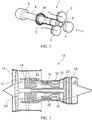
- Fig. 1 shows a typical flow forming apparatus 1.
- the apparatus 1 comprises forming rollers 2 configured to plastically deform a workpiece in the form of an initial machined generally tubular pre-form 3 over a mandrel 4 to create a shaped article.
- the workpiece 3 has to be a good fit to the mandrel 4.
- the rollers 2 move over the workpiece 3 along a mandrel axis X, and both the mandrel 4 and rollers 2 rotate.
- the workpiece is plastically formed, such that the work piece 2 is elongated and the walls of the tubular workpiece 2 are thinned, to produce a shaped article.
- forward flow forming There are two types of flow forming processes - forward flow forming and reverse flow forming.
- forward flow forming the material of the pre-form 2 flows axially in the same direction as the traversing direction of the rollers 1.
- Forward flow forming is described in US patent 2010083783 .
- reverse flow forming a distal end 3a of the pre-form is held in position against a tailstock 5, and the material flows through the rollers 2 in the opposite direction to the traversing direction of the rollers 2.
- friction between the rollers 2 and the mandrel 4 must be kept to a minimum. This is generally achieved by hardening the mandrel surface, improving the mandrel surface finish, and the application of pressure insensitive lubricants to the mandrel 4.
- the heat built up during flow forming needs to be dissipated to ensure close tolerances. This is achieved by flooding the work piece 3 with refrigerated and filtered coolant.
- the wall thickness of the flow formed sections of the tubular workpiece 3 is reduced between a minimum of 20% and a maximum of 80% during a pass, which enables modest contour changes on the outside diameter that cannot be achieved by alternative processes such as extrusion or drawing. Reducing the wall thickness consequently elongates the pre-form along the longitudinal axis. Typical elongations range between 100 and 400%.
- Flow forming has been found to be suitable for manufacturing cylindrical components for aerospace applications, including undercarriage components, hydraulic cylinders, helicopter drive shafts and thrust struts, and drive shafts for gas turbine engines.
- Materials suitable for flow forming include Inconel and some high strength steels such as 4130 Steel (i.e. steel having a nominal composition of 0.3% C, 0.8% Cr, 0.5% Mn, 0.2% Mo, 0.25% Si and the balance comprising Fe).
- 4130 Steel i.e. steel having a nominal composition of 0.3% C, 0.8% Cr, 0.5% Mn, 0.2% Mo, 0.25% Si and the balance comprising Fe.
- CMV Chromium, Molybdenum and Vanadium
- CMV is a martensitic chromium, molybdenum vanadium steel alloy conforming to BS 3S 132 and specification MSRR6097 (incorporated herein by reference) having the compositional range given in table 1 below.
- Table 1 Element Percentage by weight Carbon 0.35-0.43 Silicon 0.1 -0.35 Chromium 3.0-3.35 Molybdenum 0.8-1.10 Vanadium 0.15-0.25 Magnesium 0.4-0.7 Iron Balance
- CMV alloy also generally includes further trace elements.
- Super CMV conforms to specification MSRR6119 (incorporated herein by reference), and has a similar composition to CMV, having the same range percentage by weight of carbon, silicon, chromium, molybdenum and vanadium. However, Super CMV, is manufactured such that some further trace elements or contaminants are controlled to contain less than a specified concentration, as shown in Table 2: Table 2 Element Maximum percentage by weight Phosphorous ⁇ 0.007 Silicon ⁇ 0.002 Nickel ⁇ 0.3 Arsenic ⁇ 0.002 Antimony ⁇ 0.008
- Super CMV is subjected to a triple melting forging process, which may comprise either air melting or vacuum induction melting, followed by electro slag re-melting, followed by vacuum arc re-melting which helps control the trace elements to the levels shown in Table 2.
- the billet may then subjected to a tempering process at a temperature of approximately 560 to 580 °C to obtain an ultimate tensile strength of between 1470 MPa to 1670 MPa, compared to a typical tensile strength of CMV of between 1240 MPa and 1390 M Pa.
- M JEHAZI, G EBRAHIMI "The influence of flow-forming parameters and microstructure on the quality of D6ac steel” discusses flow forming of chromium and vanadium containing steel. An example is given in which flow forming is carried out on pre-forms having a Vickers hardness of 208.
- US2010/0236122 A1 discloses a process for manufacturing a superalloy machine gun barrel by flow forming.
- the document stresses the ability to use pre-hardened metals, in order to eliminate the need to deal with distortion from post-form heat treatment.
- the present invention describes a method of forming a shaped article which seeks to overcome some or all of the above problems.
- a method of forming a shaped article comprising:
- the invention provides a method of forming a shaped article made of a chrome vanadium molybdenum alloy which results in a shaped article relatively free of distortions.
- the step of heat treating the pre-form may be carried out to obtain a surface hardness of between 450 and 480, and preferably may be carried out to obtain a surface hardness of between 460 and 480 according to the Vickers hardness test.
- the step of heat treating the pre-form prior to the flow forming step may comprise one or both of a hardening process to increase the hardness of the pre-form, and a tempering process to reduce the hardness of the pre-form.
- the step of hearing treating the pre-form prior to the flow forming step may comprise hardening the pre-form followed by tempering the pre-form.
- the hardening process may comprise heating the pre-form to a temperature of between approximately 935 and 945 °C followed by quenching, which may comprise oil quenching to rapidly reduce the temperature of the pre-form.
- quenching which may comprise oil quenching to rapidly reduce the temperature of the pre-form.
- the hardening process gives desired properties of the material.
- the tempering process may comprise one or more tempering cycles, each tempering cycle comprising heating the pre-form to a dwell temperature of between 500 and 600 °C, and may comprise heating the pre-form to a dwell temperature between 560 and 580 °C. Each tempering cycle may comprise maintaining the pre-form at the dwell temperature for approximately 2.5 hours.
- the tempering process may comprise two tempering cycles.
- the method may comprise a stress relief heat treatment step subsequent to the flow forming step, the stress relief heat treatment step comprising heating the shaped article to a stress relief temperature of between 500° C and 575 ° C for a duration of approximately 5 hours.
- a shaped article formed according to the method of the first aspect of the invention.
- the shaped article may comprise a shaft for a gas turbine engine
- the shaped article may comprise a seal or may comprise a bushing.
- a high-bypass gas turbine engine is indicated at 10.
- the engine 10 comprises, in axial flow series, an air intake duct 11, an intake fan 12, a bypass duct 13, an intermediate pressure compressor 14, a high pressure compressor 16, a combustor 18, a high pressure turbine 20, an intermediate pressure turbine 22, a low pressure turbine 24 and an exhaust nozzle 25.
- the fan 12, compressors 14, 16 and turbines 20, 22, 24 all rotate about the major axis of the gas turbine engine 10 and so define the axial direction of gas turbine engine.
- Air is drawn through the air intake duct 11 by the intake fan 12 where it is accelerated. A significant portion of the airflow is discharged through the bypass duct 13 generating a corresponding portion of the engine 10 thrust. The remainder is drawn through the intermediate pressure compressor 14 into what is termed the core of the engine 10 where the air is compressed. A further stage of compression takes place in the high pressure compressor 16 before the air is mixed with fuel and burned in the combustor 18. The resulting hot working fluid is discharged through the high pressure turbine 20, the intermediate pressure turbine 22 and the low pressure turbine 24 in series where work is extracted from the working fluid. The work extracted drives the intake fan 12, the intermediate pressure compressor 14 and the high pressure compressor 16 via low pressure, intermediate pressure and high pressure shafts 26, 28, 30 respectively.
- shafts may also be provided, such as an angle drive (not shown).
- the working fluid which has reduced in pressure and temperature, is then expelled through the exhaust nozzle 25 and generates the remaining portion of the engine 10 thrust.
- One or more of the shafts 26, 28, 30 are formed by a flow forming method in accordance with the present invention.
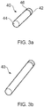
- Figs. 3a and 3b show the low pressure shaft 30 prior to and subsequent to a flow forming process respectively.
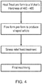
- the flow forming process is outlined in Fig. 4 .
- the low pressure shaft 30 is provided in the form of a machined pre-form 40 comprising "Super CMV" alloy having the compositional range described in tables 1 and 2 above.
- the Super CMV pre-form 40 is manufactured by a triple melting forging process, which may comprise either air melting (AM) or vacuum induction melting (VIM), followed by electro slag re-melting (ESM or EFM), followed by vacuum arc re-melting (VAM) which helps control the trace elements to the levels shown in Table 2 above.
- the pre-form may be supplied as a forged solid billet or a back extruded forging. Other feed stocks may be appropriate, such as extruded section, solid forging, radial hollow forging.
- the pre-form 40 comprises a generally hollow cup shaped blank, having an open distal end 42, a closed proximal end 44 and a flange 46 where forward flow forming is employed. Where reverse flow forming is to be employed, the pre-form comprises a tubular shaped blank having open proximal and distal ends.
- the pre-form 40 may comprise a foreshortened version of the final shaped article. As there is a geometrical relationship between the pre-form and final part then tight control over dimensions and hardness of the pre-form will reflect tolerances in the final part. Tolerances on the diameters of a pre-form are typically just as good as the final part.
- the pre-form 40 is subjected to a two stage heat treatment step.
- the first stage of the heat treatment step comprises a hardening process to increase the hardness of the pre-form 40.
- the hardening process comprises heating the pre-form to a temperature of between approximately 935 and 945 °C followed by oil quenching to rapidly reduce the temperature of the pre-form 40.
- This hardening step provides a martensitic transformation.
- the pre-form 40 typically has a hardness of more than 500 Hv, and in some cases, as much as 700 Hv, as determined by the Vickers hardness test. However, the pre-form is still relatively brittle, and requires tempering in order to reduce this brittleness.
- the Super CMV pre-form 40 is subjected to a tempering step comprising at least one tempering cycle.
- the pre-form is heated to a heat treatment temperature of between 500 °C and 600 °C, and preferably approximately between 560 and 580 °C, and is held at this temperature for a duration of approximately 2 to 3 hours in a suitable furnace, in an oxygen free environment, and preferably in a vacuum.
- the pre-form 40 is removed from the furnace and allowed to cool.
- the hardness of the pre-form is reduced. A Vickers hardness test is then performed after each tempering cycle to determine the surface hardness of the pre-form 40.
- the hardness test is carried out on a surface of the pre-form, but the hardness of the pre-form following the hardening and tempering cycles has been found to be generally consistent throughout.
- the tempering cycle is then repeated as many times as it necessary to obtain a hardness of between 420 and 480 Hv, and in some cases, for example for the component 30, to a hardness of between 460 and 480 Hv.
- pre-forms having a higher hardness are subject to excessive spring off.
- a hardness of at least 420 is required prior to the flow forming process, since areas of the pre-from that are not subject to flow forming, and will not benefit from work hardening during the flow forming process, will typically reduce in hardness because of the heat treatments applied to the flow formed article after flow forming has taken place.
- a hardness greater than 420 such as approximately 460 Hv
- a hardness greater than 480 Hv has been found to be unacceptable, due to excessive spring off.
- the pre-form is then flow formed on a flow forming apparatus such as the apparatus 1 shown in Fig. 1 .
- the flow forming process may comprise either forward or reverse flow forming.
- a forward flow forming apparatus 1 is used, having a headstock 6 for holding the proximal end 42 of the pre-form 40 in place via the flange 46.
- the apparatus 1 comprises three rollers 2, though in some cases, two or four or more rollers could be employed.
- the pre-form 40 is first placed over the mandrel 4.
- the rollers 2 are then positioned at a required position relative to the mandrel 4 and pre-form 40.
- a clearance of approximately 0.1 mm is provided between the pre-form 40 and the mandrel 4, with the rollers 2 in contact with the pre-form 40.
- the rollers 2 and mandrel 4 are then rotated, and moved axially along the mandrel 4 to deform the pre-form to form the shaped article 40 shown in Fig. 3b .
- a liquid coolant to supplied to the pre-form 40.
- a reduction in thickness of the pre-form of between 20% and 80% may be achieved with a corresponding increase in length, such that, for example, a 10mm thick preform may reduced to a 2mm to 8mm thick shaped article.
- Typical elongations range between 100 and 400%. Generally, only a single flow forming pass is required. However, several passes may be made in some cases.
- the pre-form 40 During the flow forming step, only part of the pre-form 40 is flow formed.
- the flow formed part is work hardened, resulting in a change in surface hardness.
- no work hardening is done by the flow forming process.
- the typical wall thickness following the flow forming process is too thin to allow hardening heat treatment subsequent to the flow forming process without causing unacceptable distortion. Consequently, the pre-form must have the required hardness prior to the flow forming process.
- the hardness produced by the pre-heating step prior to the flow forming step therefore provides a shaped article having the required surface hardness, while also permitting flow forming to take place.
- the flow forming step may cause residual stress in the shaped article. This may be undesirable in the final part, and so the shaped article may be subjected to an optional stress relief heat treatment step subsequent to the flow forming step.
- the stress relief heat treatment step comprising heating the shaped article to a stress relief temperature of between 500° C and 575 ° C for a duration of approximately 5 hours. This stress relief heat treatment is made at a temperature below the temperature required for hardening of CMV alloy, and so the shaped article is not deformed to a significant extent.
- the shaped article may be further machined to provide a desired surface finish, and to form surface features not provided by the flow forming process.
- the process may be applied to articles other than shafts for gas turbine engines.
- Suitable examples include stubshafts, drive shafts, seals and bushes for gas turbine engines.
- Particular examples of suitable drive shafts of gas turbine engines include low pressure fan shafts and intermediate pressure turbine shafts in three shaft engines, and low pressure shafts in two shaft engines.
Landscapes
- Chemical & Material Sciences (AREA)
- Engineering & Computer Science (AREA)
- Mechanical Engineering (AREA)
- Materials Engineering (AREA)
- Metallurgy (AREA)
- Organic Chemistry (AREA)
- Physics & Mathematics (AREA)
- Thermal Sciences (AREA)
- Crystallography & Structural Chemistry (AREA)
- Health & Medical Sciences (AREA)
- Child & Adolescent Psychology (AREA)
- Heat Treatment Of Articles (AREA)
Claims (15)
- Procédé pour former un article façonné, le procédé comprenant :la fourniture d'une préforme comprenant un alliage d'acier comprenant du chrome, du molybdène et du vanadium ;le traitement thermique de la préforme pour obtenir une dureté de surface comprise entre 420 et 480 selon l'essai de dureté Vickers ; età la suite de l'étape de traitement thermique, le fluotournage de la préforme pour former un article façonné.
- Procédé selon la revendication 1, dans lequel l'étape de traitement thermique de la préforme est effectuée pour obtenir une dureté de surface comprise entre 450 et 480 selon l'essai de dureté Vickers.
- Procédé selon la revendication 2, dans lequel l'étape de traitement thermique de la préforme est effectuée pour obtenir une dureté de surface comprise entre 460 et 480 selon l'essai de dureté Vickers.
- Procédé selon l'une quelconque des revendications précédentes, dans lequel l'étape de traitement thermique de la préforme pour obtenir une dureté de surface comprise entre 420 et 480 selon l'essai de dureté Vickers peut comprendre l'un ou les deux d'un procédé de trempe pour augmenter la dureté de la préforme, et d'un procédé de revenu pour réduire la dureté de la préforme.
- Procédé selon la revendication 4, dans lequel l'étape de traitement thermique de la préforme comprend la trempe de la préforme suivie du revenu de la préforme.
- Procédé selon la revendication 4 ou la revendication 5, dans lequel le procédé de trempe comprend le chauffage de la préforme à une température comprise entre 935 et 945 °C suivi d'un refroidissement.
- Procédé selon l'une quelconque des revendications 4 à 6, dans lequel le procédé de revenu comprend un ou plusieurs cycles de revenu, chaque cycle de revenu comprenant le chauffage de la préforme à une température de stabilisation comprise entre 500 et 600 °C.
- Procédé selon la revendication 7, dans lequel la température de stabilisation est comprise entre 560 et 580 °C.
- Procédé selon la revendication 7 ou la revendication 8, dans lequel chaque cycle de revenu comprend le maintien de la préforme à la température de stabilisation pendant environ 2,5 heures.
- Procédé selon l'une quelconque des revendications précédentes, le procédé comprenant une étape de traitement thermique de détente à la suite de l'étape de fluotournage.
- Procédé selon la revendication 10, dans lequel l'étape de traitement thermique de détente comprend le chauffage de l'article façonné à une température de recuit de détente.
- Procédé selon la revendication 11, dans lequel la température de recuit de détente est comprise entre 500 °C et 575 °C.
- Procédé selon la revendication 11 ou la revendication 12, dans lequel l'étape de traitement thermique de détente comprend le chauffage de l'article façonné à la température de recuit de détente pendant une durée approximative de 5 heures.
- Procédé selon l'une quelconque des revendications précédentes, dans lequel l'alliage d'acier comprend, en pourcentage de poids, 0,35 à 0,43% de carbone, 0,1 à 0,35% de silicium, 3,0 à 3,5% de chrome, 0,8 à 1,1% de molybdène, 0,15 à 0,25% de vanadium et 0,4 à 0,7% de magnésium, le reste étant constitué de fer.
- Procédé selon la revendication 14, dans lequel l'alliage d'acier comprend, en pourcentage de poids, moins de 0,007% de phosphore, moins de 0,002% de soufre, moins de 0,3% de nickel, moins de 0,002% d'arsenic et moins de 0,008% d'antimoine.
Applications Claiming Priority (1)
| Application Number | Priority Date | Filing Date | Title |
|---|---|---|---|
| GBGB1316829.9A GB201316829D0 (en) | 2013-09-23 | 2013-09-23 | Flow Forming method |
Publications (3)
| Publication Number | Publication Date |
|---|---|
| EP2857531A2 EP2857531A2 (fr) | 2015-04-08 |
| EP2857531A3 EP2857531A3 (fr) | 2015-04-22 |
| EP2857531B1 true EP2857531B1 (fr) | 2017-03-01 |
Family
ID=49553237
Family Applications (1)
| Application Number | Title | Priority Date | Filing Date |
|---|---|---|---|
| EP14183234.5A Not-in-force EP2857531B1 (fr) | 2013-09-23 | 2014-09-02 | Procédé de fluotournage |
Country Status (3)
| Country | Link |
|---|---|
| US (1) | US20150083284A1 (fr) |
| EP (1) | EP2857531B1 (fr) |
| GB (1) | GB201316829D0 (fr) |
Families Citing this family (7)
| Publication number | Priority date | Publication date | Assignee | Title |
|---|---|---|---|---|
| US10118259B1 (en) | 2012-12-11 | 2018-11-06 | Ati Properties Llc | Corrosion resistant bimetallic tube manufactured by a two-step process |
| CA2953819A1 (fr) * | 2014-06-27 | 2015-12-30 | Ati Properties Llc | Fluotournage de tubes en alliage resistant a la corrosion et tube fabrique selon cette technique |
| CN105543463B (zh) * | 2015-12-28 | 2019-12-27 | 河南北方红阳机电有限公司 | 超高强度d6ac钢薄壁管件气氛保护热处理工艺 |
| US11185905B2 (en) | 2018-03-23 | 2021-11-30 | Raytheon Technologies Corporation | Systems and methods for improving backward flow forming of shafts |
| US11737851B2 (en) | 2018-06-28 | 2023-08-29 | Cook Medical Technologies Llc | Medical devices for magnetic resonance imaging and related methods |
| DE102020203955A1 (de) | 2020-03-26 | 2021-09-30 | Rolls-Royce Deutschland Ltd & Co Kg | Brennkammergehäuse und Herstellungsverfahren |
| DE102021109866B3 (de) * | 2021-04-20 | 2022-08-11 | Thyssenkrupp Steel Europe Ag | Verfahren zur Herstellung eines Druckbehälters |
Citations (5)
| Publication number | Priority date | Publication date | Assignee | Title |
|---|---|---|---|---|
| US20040166360A1 (en) | 2001-10-23 | 2004-08-26 | Kazuhito Imai | Hot press forming method, and a plated steel material therefor and its manufacturing method |
| US20060060270A1 (en) | 2004-09-22 | 2006-03-23 | Klueh Ronald L | Nano-scale nitride-particle-strengthened high-temperature wrought ferritic and martensitic steels |
| US20060070688A1 (en) | 2004-10-01 | 2006-04-06 | Dynamic Machine Works, Inc. | Alpha-beta titanium alloy tubes and methods of flowforming the same |
| US20100136369A1 (en) | 2008-11-18 | 2010-06-03 | Raghavan Ayer | High strength and toughness steel structures by friction stir welding |
| US20120042992A1 (en) | 2009-03-30 | 2012-02-23 | Sumitomo Metal Industries, Ltd. | Method for manufacturing seamless pipes |
Family Cites Families (6)
| Publication number | Priority date | Publication date | Assignee | Title |
|---|---|---|---|---|
| US4023389A (en) * | 1976-06-16 | 1977-05-17 | Rockwell International Corporation | Method of flow forming |
| JPH03104816A (ja) * | 1989-07-27 | 1991-05-01 | Sumitomo Metal Ind Ltd | 軟窒化鋼の製造方法 |
| JP2542111B2 (ja) * | 1990-07-31 | 1996-10-09 | 日産自動車株式会社 | スピニング加工方法 |
| DE4323167C1 (de) | 1993-07-10 | 1994-05-19 | Leifeld Gmbh & Co | Verfahren zum Herstellen eines Hohlkörpers aus Stahl mit einer Innen- und/oder Außenprofilierung |
| US20100236122A1 (en) * | 2006-07-26 | 2010-09-23 | Fonte Matthew V | Flowforming Gun Barrels and Similar Tubular Devices |
| DE102009049398C5 (de) * | 2009-10-14 | 2015-05-07 | Benteler Automobiltechnik Gmbh | Verfahren zur Herstellung eines Strukturbauteils für ein Kraftfahrzeug und Strukturbauteil |
-
2013
- 2013-09-23 GB GBGB1316829.9A patent/GB201316829D0/en not_active Ceased
-
2014
- 2014-09-02 EP EP14183234.5A patent/EP2857531B1/fr not_active Not-in-force
- 2014-09-03 US US14/475,654 patent/US20150083284A1/en not_active Abandoned
Patent Citations (5)
| Publication number | Priority date | Publication date | Assignee | Title |
|---|---|---|---|---|
| US20040166360A1 (en) | 2001-10-23 | 2004-08-26 | Kazuhito Imai | Hot press forming method, and a plated steel material therefor and its manufacturing method |
| US20060060270A1 (en) | 2004-09-22 | 2006-03-23 | Klueh Ronald L | Nano-scale nitride-particle-strengthened high-temperature wrought ferritic and martensitic steels |
| US20060070688A1 (en) | 2004-10-01 | 2006-04-06 | Dynamic Machine Works, Inc. | Alpha-beta titanium alloy tubes and methods of flowforming the same |
| US20100136369A1 (en) | 2008-11-18 | 2010-06-03 | Raghavan Ayer | High strength and toughness steel structures by friction stir welding |
| US20120042992A1 (en) | 2009-03-30 | 2012-02-23 | Sumitomo Metal Industries, Ltd. | Method for manufacturing seamless pipes |
Non-Patent Citations (2)
| Title |
|---|
| BIKRAMJIT POTTER ET AL.: "Effect of preform heat treatment on the flow formability and mechanical properties of AISI4340 steel", MATERIALS AND DESIGNS, vol. 37, 2012, pages 174 - 181, XP055173726 |
| FONTE, MATTHEW ET AL.: "FLOWFORMING CYLINDRICAL COMPONENTS", ADVANCED MATERIAL & PROCESSES, September 2005 (2005-09-01), pages 59 - 61, XP055441498 |
Also Published As
| Publication number | Publication date |
|---|---|
| US20150083284A1 (en) | 2015-03-26 |
| EP2857531A3 (fr) | 2015-04-22 |
| GB201316829D0 (en) | 2013-11-06 |
| EP2857531A2 (fr) | 2015-04-08 |
Similar Documents
| Publication | Publication Date | Title |
|---|---|---|
| EP2857531A2 (fr) | Procédé de fluotournage | |
| JP3605830B2 (ja) | 連続焼鈍炉、焼鈍方法及び転がり軸受の内外輪の製造方法 | |
| DE102007023087B4 (de) | Verfahren zur Herstellung eines Nockens | |
| CN111621623B (zh) | 一种薄壁环形类渗碳直淬零件的热处理方法 | |
| AU690147B2 (en) | One-piece hollow camshaft and process for producing it | |
| DE102005027259B4 (de) | Verfahren zur Herstellung von metallischen Bauteilen durch Halbwarm-Umformung | |
| EP2140950A1 (fr) | Tuyau en acier sans soudure, fini à froid, pour un arbre de transmission moulé d'un seul tenant, arbre de transmission utilisant le tuyau et procédé de fabrication du tuyau en acier sans soudure, fini à froid | |
| US20120031516A1 (en) | Axle Sleeve Manufacturing Process | |
| JP6312988B2 (ja) | 大型ピストンリングの製造方法、大型ピストンリング素材、及び大型ピストンリング。 | |
| JP4563524B2 (ja) | 焼入れ鋼部品の製造方法 | |
| CN103397293A (zh) | 重型机械零部件的渗碳工艺 | |
| CN107150205A (zh) | 用于报废大型锻钢支承辊循环再生的方法 | |
| JP2014237152A5 (fr) | ||
| DE102015221842A1 (de) | Verfahren zur Herstellung einer Getriebewelle | |
| JP2000063952A (ja) | 中空軸の製造方法 | |
| CN111593173A (zh) | 一种非调质钢制件的稳定控制冷却的新方法 | |
| JP2009197899A (ja) | 複列アンギュラ軸受 | |
| DE102017209881A1 (de) | Verfahren zur Fertigung eines gehärteten Getriebebauteils und hierfür verwendbares Umformwerkzeug mit gekühltem Gesenk | |
| CN113231468A (zh) | 低硬度38CrMoAl棒材的生产方法 | |
| WO2025217952A1 (fr) | Procédé de fabrication d'une cannelure flexible d'un réducteur harmonique | |
| CN118664273A (zh) | 一种谐波减速器柔轮的加工工艺 | |
| EP2971210B1 (fr) | Composant configuré à partir d'acier inoxydable martensitique | |
| JP7779711B2 (ja) | 歯車の製造方法及び歯車 | |
| RU2776341C1 (ru) | Способ термической обработки деталей подшипников из теплостойкой подшипниковой стали (варианты) и деталь подшипника, полученная указанным способом | |
| US20240300005A1 (en) | Radial forging for the manufacture of ball screw actuator shafts |
Legal Events
| Date | Code | Title | Description |
|---|---|---|---|
| PUAL | Search report despatched |
Free format text: ORIGINAL CODE: 0009013 |
|
| PUAI | Public reference made under article 153(3) epc to a published international application that has entered the european phase |
Free format text: ORIGINAL CODE: 0009012 |
|
| 17P | Request for examination filed |
Effective date: 20140902 |
|
| AK | Designated contracting states |
Kind code of ref document: A2 Designated state(s): AL AT BE BG CH CY CZ DE DK EE ES FI FR GB GR HR HU IE IS IT LI LT LU LV MC MK MT NL NO PL PT RO RS SE SI SK SM TR |
|
| AX | Request for extension of the european patent |
Extension state: BA ME |
|
| AK | Designated contracting states |
Kind code of ref document: A3 Designated state(s): AL AT BE BG CH CY CZ DE DK EE ES FI FR GB GR HR HU IE IS IT LI LT LU LV MC MK MT NL NO PL PT RO RS SE SI SK SM TR |
|
| AX | Request for extension of the european patent |
Extension state: BA ME |
|
| RIC1 | Information provided on ipc code assigned before grant |
Ipc: C21D 1/25 20060101ALI20150316BHEP Ipc: B21D 22/14 20060101ALI20150316BHEP Ipc: C21D 9/28 20060101ALI20150316BHEP Ipc: C21D 8/10 20060101ALI20150316BHEP Ipc: C21D 9/08 20060101AFI20150316BHEP |
|
| R17P | Request for examination filed (corrected) |
Effective date: 20150428 |
|
| RBV | Designated contracting states (corrected) |
Designated state(s): AL AT BE BG CH CY CZ DE DK EE ES FI FR GB GR HR HU IE IS IT LI LT LU LV MC MK MT NL NO PL PT RO RS SE SI SK SM TR |
|
| RAP1 | Party data changed (applicant data changed or rights of an application transferred) |
Owner name: ROLLS-ROYCE PLC |
|
| REG | Reference to a national code |
Ref country code: DE Ref legal event code: R079 Ref document number: 602014007058 Country of ref document: DE Free format text: PREVIOUS MAIN CLASS: C21D0008100000 Ipc: C21D0009080000 |
|
| GRAP | Despatch of communication of intention to grant a patent |
Free format text: ORIGINAL CODE: EPIDOSNIGR1 |
|
| STAA | Information on the status of an ep patent application or granted ep patent |
Free format text: STATUS: GRANT OF PATENT IS INTENDED |
|
| RIC1 | Information provided on ipc code assigned before grant |
Ipc: C21D 9/28 20060101ALI20161114BHEP Ipc: C21D 6/00 20060101ALI20161114BHEP Ipc: C21D 8/10 20060101ALI20161114BHEP Ipc: C21D 9/08 20060101AFI20161114BHEP Ipc: C22C 38/22 20060101ALI20161114BHEP Ipc: B21D 22/14 20060101ALI20161114BHEP Ipc: C21D 1/25 20060101ALI20161114BHEP Ipc: C22C 38/24 20060101ALI20161114BHEP |
|
| INTG | Intention to grant announced |
Effective date: 20161208 |
|
| TPAC | Observations filed by third parties |
Free format text: ORIGINAL CODE: EPIDOSNTIPA |
|
| GRAS | Grant fee paid |
Free format text: ORIGINAL CODE: EPIDOSNIGR3 |
|
| GRAA | (expected) grant |
Free format text: ORIGINAL CODE: 0009210 |
|
| STAA | Information on the status of an ep patent application or granted ep patent |
Free format text: STATUS: THE PATENT HAS BEEN GRANTED |
|
| AK | Designated contracting states |
Kind code of ref document: B1 Designated state(s): AL AT BE BG CH CY CZ DE DK EE ES FI FR GB GR HR HU IE IS IT LI LT LU LV MC MK MT NL NO PL PT RO RS SE SI SK SM TR |
|
| REG | Reference to a national code |
Ref country code: GB Ref legal event code: FG4D |
|
| REG | Reference to a national code |
Ref country code: CH Ref legal event code: EP Ref country code: AT Ref legal event code: REF Ref document number: 871425 Country of ref document: AT Kind code of ref document: T Effective date: 20170315 |
|
| REG | Reference to a national code |
Ref country code: IE Ref legal event code: FG4D |
|
| REG | Reference to a national code |
Ref country code: DE Ref legal event code: R096 Ref document number: 602014007058 Country of ref document: DE |
|
| REG | Reference to a national code |
Ref country code: NL Ref legal event code: MP Effective date: 20170301 |
|
| REG | Reference to a national code |
Ref country code: LT Ref legal event code: MG4D |
|
| REG | Reference to a national code |
Ref country code: AT Ref legal event code: MK05 Ref document number: 871425 Country of ref document: AT Kind code of ref document: T Effective date: 20170301 |
|
| PG25 | Lapsed in a contracting state [announced via postgrant information from national office to epo] |
Ref country code: FI Free format text: LAPSE BECAUSE OF FAILURE TO SUBMIT A TRANSLATION OF THE DESCRIPTION OR TO PAY THE FEE WITHIN THE PRESCRIBED TIME-LIMIT Effective date: 20170301 Ref country code: HR Free format text: LAPSE BECAUSE OF FAILURE TO SUBMIT A TRANSLATION OF THE DESCRIPTION OR TO PAY THE FEE WITHIN THE PRESCRIBED TIME-LIMIT Effective date: 20170301 Ref country code: LT Free format text: LAPSE BECAUSE OF FAILURE TO SUBMIT A TRANSLATION OF THE DESCRIPTION OR TO PAY THE FEE WITHIN THE PRESCRIBED TIME-LIMIT Effective date: 20170301 Ref country code: NO Free format text: LAPSE BECAUSE OF FAILURE TO SUBMIT A TRANSLATION OF THE DESCRIPTION OR TO PAY THE FEE WITHIN THE PRESCRIBED TIME-LIMIT Effective date: 20170601 Ref country code: GR Free format text: LAPSE BECAUSE OF FAILURE TO SUBMIT A TRANSLATION OF THE DESCRIPTION OR TO PAY THE FEE WITHIN THE PRESCRIBED TIME-LIMIT Effective date: 20170602 |
|
| PG25 | Lapsed in a contracting state [announced via postgrant information from national office to epo] |
Ref country code: AT Free format text: LAPSE BECAUSE OF FAILURE TO SUBMIT A TRANSLATION OF THE DESCRIPTION OR TO PAY THE FEE WITHIN THE PRESCRIBED TIME-LIMIT Effective date: 20170301 Ref country code: SE Free format text: LAPSE BECAUSE OF FAILURE TO SUBMIT A TRANSLATION OF THE DESCRIPTION OR TO PAY THE FEE WITHIN THE PRESCRIBED TIME-LIMIT Effective date: 20170301 Ref country code: RS Free format text: LAPSE BECAUSE OF FAILURE TO SUBMIT A TRANSLATION OF THE DESCRIPTION OR TO PAY THE FEE WITHIN THE PRESCRIBED TIME-LIMIT Effective date: 20170301 Ref country code: BG Free format text: LAPSE BECAUSE OF FAILURE TO SUBMIT A TRANSLATION OF THE DESCRIPTION OR TO PAY THE FEE WITHIN THE PRESCRIBED TIME-LIMIT Effective date: 20170601 Ref country code: LV Free format text: LAPSE BECAUSE OF FAILURE TO SUBMIT A TRANSLATION OF THE DESCRIPTION OR TO PAY THE FEE WITHIN THE PRESCRIBED TIME-LIMIT Effective date: 20170301 Ref country code: ES Free format text: LAPSE BECAUSE OF FAILURE TO SUBMIT A TRANSLATION OF THE DESCRIPTION OR TO PAY THE FEE WITHIN THE PRESCRIBED TIME-LIMIT Effective date: 20170301 |
|
| REG | Reference to a national code |
Ref country code: FR Ref legal event code: PLFP Year of fee payment: 4 |
|
| PG25 | Lapsed in a contracting state [announced via postgrant information from national office to epo] |
Ref country code: NL Free format text: LAPSE BECAUSE OF FAILURE TO SUBMIT A TRANSLATION OF THE DESCRIPTION OR TO PAY THE FEE WITHIN THE PRESCRIBED TIME-LIMIT Effective date: 20170301 |
|
| PG25 | Lapsed in a contracting state [announced via postgrant information from national office to epo] |
Ref country code: CZ Free format text: LAPSE BECAUSE OF FAILURE TO SUBMIT A TRANSLATION OF THE DESCRIPTION OR TO PAY THE FEE WITHIN THE PRESCRIBED TIME-LIMIT Effective date: 20170301 Ref country code: RO Free format text: LAPSE BECAUSE OF FAILURE TO SUBMIT A TRANSLATION OF THE DESCRIPTION OR TO PAY THE FEE WITHIN THE PRESCRIBED TIME-LIMIT Effective date: 20170301 Ref country code: SK Free format text: LAPSE BECAUSE OF FAILURE TO SUBMIT A TRANSLATION OF THE DESCRIPTION OR TO PAY THE FEE WITHIN THE PRESCRIBED TIME-LIMIT Effective date: 20170301 Ref country code: EE Free format text: LAPSE BECAUSE OF FAILURE TO SUBMIT A TRANSLATION OF THE DESCRIPTION OR TO PAY THE FEE WITHIN THE PRESCRIBED TIME-LIMIT Effective date: 20170301 Ref country code: IT Free format text: LAPSE BECAUSE OF FAILURE TO SUBMIT A TRANSLATION OF THE DESCRIPTION OR TO PAY THE FEE WITHIN THE PRESCRIBED TIME-LIMIT Effective date: 20170301 |
|
| REG | Reference to a national code |
Ref country code: DE Ref legal event code: R026 Ref document number: 602014007058 Country of ref document: DE |
|
| PG25 | Lapsed in a contracting state [announced via postgrant information from national office to epo] |
Ref country code: PL Free format text: LAPSE BECAUSE OF FAILURE TO SUBMIT A TRANSLATION OF THE DESCRIPTION OR TO PAY THE FEE WITHIN THE PRESCRIBED TIME-LIMIT Effective date: 20170301 Ref country code: IS Free format text: LAPSE BECAUSE OF FAILURE TO SUBMIT A TRANSLATION OF THE DESCRIPTION OR TO PAY THE FEE WITHIN THE PRESCRIBED TIME-LIMIT Effective date: 20170701 Ref country code: SM Free format text: LAPSE BECAUSE OF FAILURE TO SUBMIT A TRANSLATION OF THE DESCRIPTION OR TO PAY THE FEE WITHIN THE PRESCRIBED TIME-LIMIT Effective date: 20170301 Ref country code: PT Free format text: LAPSE BECAUSE OF FAILURE TO SUBMIT A TRANSLATION OF THE DESCRIPTION OR TO PAY THE FEE WITHIN THE PRESCRIBED TIME-LIMIT Effective date: 20170703 |
|
| PLBI | Opposition filed |
Free format text: ORIGINAL CODE: 0009260 |
|
| PLAX | Notice of opposition and request to file observation + time limit sent |
Free format text: ORIGINAL CODE: EPIDOSNOBS2 |
|
| 26 | Opposition filed |
Opponent name: WINKELMANN MSR TECHNOLOGY GMBH & CO. KG Effective date: 20171122 |
|
| PG25 | Lapsed in a contracting state [announced via postgrant information from national office to epo] |
Ref country code: DK Free format text: LAPSE BECAUSE OF FAILURE TO SUBMIT A TRANSLATION OF THE DESCRIPTION OR TO PAY THE FEE WITHIN THE PRESCRIBED TIME-LIMIT Effective date: 20170301 |
|
| PG25 | Lapsed in a contracting state [announced via postgrant information from national office to epo] |
Ref country code: SI Free format text: LAPSE BECAUSE OF FAILURE TO SUBMIT A TRANSLATION OF THE DESCRIPTION OR TO PAY THE FEE WITHIN THE PRESCRIBED TIME-LIMIT Effective date: 20170301 |
|
| PLBB | Reply of patent proprietor to notice(s) of opposition received |
Free format text: ORIGINAL CODE: EPIDOSNOBS3 |
|
| REG | Reference to a national code |
Ref country code: CH Ref legal event code: PL |
|
| PG25 | Lapsed in a contracting state [announced via postgrant information from national office to epo] |
Ref country code: MC Free format text: LAPSE BECAUSE OF FAILURE TO SUBMIT A TRANSLATION OF THE DESCRIPTION OR TO PAY THE FEE WITHIN THE PRESCRIBED TIME-LIMIT Effective date: 20170301 |
|
| REG | Reference to a national code |
Ref country code: IE Ref legal event code: MM4A |
|
| REG | Reference to a national code |
Ref country code: BE Ref legal event code: MM Effective date: 20170930 |
|
| PG25 | Lapsed in a contracting state [announced via postgrant information from national office to epo] |
Ref country code: LU Free format text: LAPSE BECAUSE OF NON-PAYMENT OF DUE FEES Effective date: 20170902 |
|
| PG25 | Lapsed in a contracting state [announced via postgrant information from national office to epo] |
Ref country code: IE Free format text: LAPSE BECAUSE OF NON-PAYMENT OF DUE FEES Effective date: 20170902 Ref country code: LI Free format text: LAPSE BECAUSE OF NON-PAYMENT OF DUE FEES Effective date: 20170930 Ref country code: CH Free format text: LAPSE BECAUSE OF NON-PAYMENT OF DUE FEES Effective date: 20170930 |
|
| PG25 | Lapsed in a contracting state [announced via postgrant information from national office to epo] |
Ref country code: BE Free format text: LAPSE BECAUSE OF NON-PAYMENT OF DUE FEES Effective date: 20170930 |
|
| REG | Reference to a national code |
Ref country code: FR Ref legal event code: PLFP Year of fee payment: 5 |
|
| PG25 | Lapsed in a contracting state [announced via postgrant information from national office to epo] |
Ref country code: MT Free format text: LAPSE BECAUSE OF NON-PAYMENT OF DUE FEES Effective date: 20170902 |
|
| REG | Reference to a national code |
Ref country code: DE Ref legal event code: R100 Ref document number: 602014007058 Country of ref document: DE |
|
| PLCK | Communication despatched that opposition was rejected |
Free format text: ORIGINAL CODE: EPIDOSNREJ1 |
|
| PG25 | Lapsed in a contracting state [announced via postgrant information from national office to epo] |
Ref country code: HU Free format text: LAPSE BECAUSE OF FAILURE TO SUBMIT A TRANSLATION OF THE DESCRIPTION OR TO PAY THE FEE WITHIN THE PRESCRIBED TIME-LIMIT; INVALID AB INITIO Effective date: 20140902 |
|
| PLBN | Opposition rejected |
Free format text: ORIGINAL CODE: 0009273 |
|
| STAA | Information on the status of an ep patent application or granted ep patent |
Free format text: STATUS: OPPOSITION REJECTED |
|
| 27O | Opposition rejected |
Effective date: 20190328 |
|
| PG25 | Lapsed in a contracting state [announced via postgrant information from national office to epo] |
Ref country code: CY Free format text: LAPSE BECAUSE OF FAILURE TO SUBMIT A TRANSLATION OF THE DESCRIPTION OR TO PAY THE FEE WITHIN THE PRESCRIBED TIME-LIMIT Effective date: 20170301 |
|
| PG25 | Lapsed in a contracting state [announced via postgrant information from national office to epo] |
Ref country code: MK Free format text: LAPSE BECAUSE OF FAILURE TO SUBMIT A TRANSLATION OF THE DESCRIPTION OR TO PAY THE FEE WITHIN THE PRESCRIBED TIME-LIMIT Effective date: 20170301 |
|
| PG25 | Lapsed in a contracting state [announced via postgrant information from national office to epo] |
Ref country code: TR Free format text: LAPSE BECAUSE OF FAILURE TO SUBMIT A TRANSLATION OF THE DESCRIPTION OR TO PAY THE FEE WITHIN THE PRESCRIBED TIME-LIMIT Effective date: 20170301 |
|
| PG25 | Lapsed in a contracting state [announced via postgrant information from national office to epo] |
Ref country code: AL Free format text: LAPSE BECAUSE OF FAILURE TO SUBMIT A TRANSLATION OF THE DESCRIPTION OR TO PAY THE FEE WITHIN THE PRESCRIBED TIME-LIMIT Effective date: 20170301 |
|
| PGFP | Annual fee paid to national office [announced via postgrant information from national office to epo] |
Ref country code: GB Payment date: 20200925 Year of fee payment: 7 Ref country code: FR Payment date: 20200928 Year of fee payment: 7 |
|
| PGFP | Annual fee paid to national office [announced via postgrant information from national office to epo] |
Ref country code: DE Payment date: 20201127 Year of fee payment: 7 |
|
| REG | Reference to a national code |
Ref country code: DE Ref legal event code: R119 Ref document number: 602014007058 Country of ref document: DE |
|
| GBPC | Gb: european patent ceased through non-payment of renewal fee |
Effective date: 20210902 |
|
| PG25 | Lapsed in a contracting state [announced via postgrant information from national office to epo] |
Ref country code: GB Free format text: LAPSE BECAUSE OF NON-PAYMENT OF DUE FEES Effective date: 20210902 Ref country code: FR Free format text: LAPSE BECAUSE OF NON-PAYMENT OF DUE FEES Effective date: 20210930 Ref country code: DE Free format text: LAPSE BECAUSE OF NON-PAYMENT OF DUE FEES Effective date: 20220401 |